Research of brick dynamic strength when
subjected to shock loading by method of
computer modelling
Andrei Plyaskin1, *, Nikolai Belov1,Nikolai Yugov2, Artem Ryshkov1, Aleksei Yugov1, and Nina Matskevich1
1Tomsk State University of Architecture and Building, 634003, Russia
2Tomsk State University of Control Systems and Radioelectronics, 634050, Russia
Abstract. The study represents the mathematical model of distorting and destruction of ordinary brick and masonry when subjected to shock-wave loadings. The research of the impact dynamic strength of the masonry's two fragments to the steel drop-weight of 1-2 m, weighing 197-1000 kg, was conducted by using the method of the computer modelling.
1 Introduction
For the civil structures, it tends to increase the origination and the short-time load action of shock and bursting conditions.
In Tomsk State University of Architecture and Building, the symbolic behavioural model was generated, taking into consideration the shock-wave loading of one-piece structure environments, including concrete, reinforced concrete, and fiber reinforced concrete, to make the strength design of the structural engineering elements to the explosion and to the impact loading.
The studies of the structural behaviour, containing the masonry when subjected to shock-wave loading, are egregiously insufficient. The research results of the investigational studies of the masonry's segments when subjected to the static and dynamic loadings are represented in [1]. The mathematical modelling and the calculations of brick structures when subjected to the dynamic loadings are meant to be an essentially relevant objective.
The mathematical model, which describes the dynamic fracture process of brick, under the phenomenal approach, is shown in this work. During the mathematical model development of the distortion and the destruction of ordinary brick it is necessary to take in account its original porosity, which can amount to 13%.
The software package "Analysis of adiabatic non-standard flows-3" ("RANET-3") is designed for the tasks of impact and explosion in the full three-dimensional view with the modified finite-element method. The upgrade of the method does not lie in using the mass matrix as in FE method, and the mass of elements is evenly extended over its points. That allows to integrate the motion equation on a direct basis, so it relieves from the necessity of
making up the stiffness matrix of the construction. The load is given by means of the speed time change of adjoining surface.
From physical standpoint, the reinforced concrete takes the form of porous elasto-plastic substance. The mathematical model of porous elasto-plastic environment is described by the mass impulse, the energy conservation equations, the equation of state, the Prandtl-Reuss equation, the Mises yield criterion and the equation of the porous substance.
Two fracture processes are dealt with stretching and pressure for the elastic-plastic porous substance.
2 Mathematical model
The specific volume of the porous substance is represented as the sum of the specific volume of matrix material and the porosity: mp. The material porosity is
characterized by the relative void volume
, or the parameter / m, which areconnected by the dependency
1/ (1
). The system of equation, describing the porouselastic-plastic substance motion, is:
0 d
dV dtV ,
d
dV dS
dtV u Snσ ,
V S
d
EdV dS
dt
n σ u , 2 j s
e s (1)
2 2 :
3T
s s ,
2
0 0 0
0 0 2
0 (1 / 2) 1 p , (1 ) c s
t – time; V – integrating volume; S – its surface; n – outer normal unit vector; ρ – imporosity; = – pg+s – stress tensor; s – its deviator; p – pressure; g – metric tensor; u – velocity vector; E = ε +
u·u/2 – total energy per unit of volume; ε – internal energy per unit of volume; e=d–(d:g)g/3 – strain-rate deviator; ( T) / 2
d u u – strain velocity tensor; sJ=s s ω – ω
s– differential coefficient of stress deviator in the matter of Jaumann-Noll; μ = μ0·(1 – ξ)[1– (6·ρ0·c02 +12·μ0)·ξ/(9·ρ0·c02 + 8·μ0)], σT = Y0/α – effective shearing rigidity and yield stress; ω = (uT–u)/2
– vorticity tensor; ρ0, c0, μ0,Y0, s0 – matrix material constants; 1 o / . The parameter λ is
eliminated with yield criterion. с0 and s0 are the slopes of the linear effect of shock-wave speed D
with the mass velocity u (D = c0+s0u).
The system (1) is focused on the equations, which connected the pressure p and the porosity during the compression:
2
ln( )
3 T 1
p
2
0 0 0
0 0 2
0
(1 / 2) 2
ln( ) 0
3 1
(1 ) T
c s (2)
2
0 0 0 0 0
0
(1 / 2)
ln 0
2 1
(1 ) s
c a s
(3)
The brick material is the burnt clay when subjected to the dynamic loading up to the fulfilment of the strength condition that is described by the model of one-dimensional elastic solid, which has stress-strain properties of brick.
The criterion, offered to the concrete, is used in capacity of the strength condition [2]:
3 2 322 1
3 1 (1 ) 1 ( ) ,
2 3
J J
J AI B C
(4)
1,
I J2, J3 are the first invariant of the stress tensor, the second and the third ones are thoroughly the
invariants of deviatoric stress;ARcRp;BR Rc p;
2 3 ; c c p T C R R
Rc, Rp,Tc are uniaxial
compressive strength, tensile strength and pure shift.
The surface (4) for isotropic materials shall meet the convexity condition (in compliance with Drucker's and Hill's postulates), which imposes constraints on the following designed parameters
0,530 c 0,577 c p
T R R
The numeral values of A, B, Care determined by the ultimate stress of the brick under
tension, compression and pure shift when subjected to the dynamic loading. After the fulfilment of the strength condition, the material is considered to be cracked.
The process of the cracked material fragmenting and the cracked material behaviour are given within the model of porous elastic-plastic substance.
The fragmentation of cracked material, exposed to the tension stress, is on when the
percentage of the relative voids comes up to the critical value 1
. If the material,
failed by cracking, is exposed to the compression stress, the fragmenting criterion is meant to be the intensity limit of plastic floweu
: * 2 2 1 2 3 , 3 u
e T T
1
T and T2 are the first and the second tensor variants of deformation.
The cracked material is modelled by granulated substance, which withstands the compressive load, but does not withstand the tensile stress.
This model is put into action by the software package "Analysis of adiabatic non-standard flows-3" ("RANET-3"), which allows to achieve the tasks of impact shock and explosion in the full three-dimensional view [3].
3 Calculation data
brick. The parameters of the constitutive equation are shown in Table 1.
Table 1. Parameters of the constitutive equation.
Material ρ0, g/cm3 α0 с0, cm/ms s0 γ0 α00
Brick 2.183 1.149 0.332 1.02 2.0 1.001
Mortar 1.65 1.03125 0.128 1.42 2.0 1.001
In Table 1, the minimum porosity of the material is indicated by means of α00, which
can not be prevented under any compression. The physical and mechanical properties and parameters of the cracking model of the brick M100 are represented in Table 2.
Table 2. The physical and mechanical properties of the brick M100.
Material µ0, GPa Rc,
GPa R
p, GPa Rp, GPa Y0,
GPa a
s,
GPa ξ* * u
e
Brick 2.27273 0.014 0.00126 0.00238 0.0058 0.0039 0.30 0.26
Mortar 1.9027 0.0105 0.00098 0.001792 0.0036 0.0024 0.30 0.26
The load of the drop-weight to the face surface of the upper brick is modulated by the mass velocity demand u(x, y, z) on the "steel-brick" adjoining surface: u(x, y, z) = u0. It
was considered that the contact surface pressure in time T1 remained constant and equaled
to P0. The time of load T1 was defined according to the Newton's second law of
motionmdu P S0 1
dt , where m was the lading drop-weight and S1 was the area of the brick
face surface. One should consider the fact that the speed u(x, y, z) is changing in time from
V0 to 0, 1 0 1 0 mV T
S P
, whereV0 2gh is the speed of lading weight at the time of
interaction. For the impact velocity V0, the numerical values P0 and the mass velocity u0 on
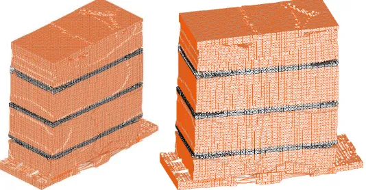
the "steel-brick" adjoining surface were defined by using the graphic approach with the impact adiabats of steel and brick. In Fig. 1, there are calculation data of the dynamic strength of the masonry fragment, consisted of four bricks with 1 cm mortar bed between them. The data are represented by the time of the impact shock of the steel falling weight of 500 kg at 2 m height, being on the pile-driver (V0 = 6,26 m/s, u0 = 6,1 m/s, P0 = 0,04 GPa,
T1 = 2541 ms). The calculation was made to the time moment of 4007 ms.
As is seen from Fig. 1, where the configuration of masonry is represented, the lower brick is heavily cracked at the bottom of it; the upper one is partially destroyed. The second and the third bricks are not broken. The small fraction of mortar is crumbled away in the first and third lays. The bottom of masonry is destroyed to a depth of 2 cm and it is shifted. The brick crack is clearly visible on the first brick close to the face surface.
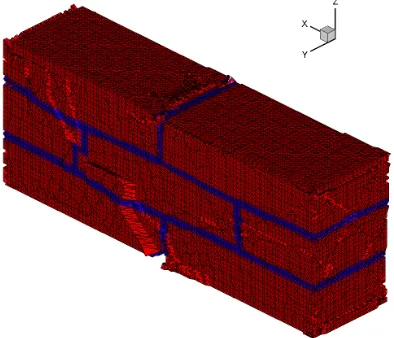
In Fig. 2 and 3, the calculation data of impact interaction of steel loading with 1000 kg weight are demonstrated. The data are represented at the fall of 2 m height with a segment of the brick masonry of the second type (V0 = 6, 26 m/s, u0 = 6,1 m/s, P0 = 0, 04 GPa, T1 =
2541 ms). The first and the third lays of the masonry are made up of two single-piece bricks, divided by the lay of the sand and cement mortar in 1 cm thickness. The second lay of the masonry is made up of the single-piece brick and its two halves. The calculation is made to the time moment of 3000 ms.
Fig. 2. The isometrics of the effective plastic strain in the center axial section to the time moment of 3000 ms.
Fig. 3. The configuration of the brick masonry 3×2 is affected by the rectangular impulse with the time duration of 2541,7 ms and at the speed of 6,1 m/s to the time moment of 3000 ms.
under the first brick is destroyed. The strain figure and the fracture pattern of the masonry fragment of the second type is shown on Fig. 3.
References
1. D.G. Kopanica, Vestnik TGASU, E 4, 157 (2012)
2. Ju.M. Bazhenov, Beton pri dinamicheskom nagruzhenii, (Izd-vo literatury po stroitel'stvu, Moscow, 1970)
3. N.T. Jugov, N.N. Belov, A.A. Jugov, Raschet adiabaticheskih nestacionarnyh techenij v trehmernoj postanovke RANET-3 (Federal'naja sluzhba po intellektual'noj sobstvennosti, patentam i tovarnym znakam. Svidetel'stvo o gosudarstvennoj registracii programm dlja JeVM №201061 1042, Moscow, 2010)
4. R.F. Trunin, G.V. Simakov, I.P. Dudoladov, G.S. Telegin, I.P. Trusov, Svojstva kondensirovannyh veshchestv pri vysokih davleniyah i temperaturah, E 16, 249VNIIEHF, Arzamas (1992)