Universal Filtered Multicarrier Transmitter
Implementation using FFT and FIR Filter
Pritam Kumari
1, Prof. Shivraj Singh
2M. E. Scholar, Department of Electronics and Communication Engg., TIT, Bhopal, India1
Assistant Professor, Department of Electronics and Communication Engg., TIT, Bhopal, India 2
ABSTRACT: Machine to machine (M2M) and Internet of things (IoT) communication systems are characterized by short and bursty communication cycles. Devices may also have very low duty cycles to increase battery lifetime. In this paper, we have proposed reduced complexity hardware solutions for all two constituent blocks, i.e., inverse fast fourier transform (IFFT) and finite impulse response (FIR) filter blocks of a UFMC transmitter. For IFFT part, a reduced complexity using Radix-2 decimation in a time technique is presented, where more than 30-40% computations can be avoided. It is also shown that how five times less number of multipliers can be used in an FIR filter to simplify filter architecture.
Upon comparison, the proposed algorithm based on IFFT and FIR filter is fast than previous algorithm. This all design and experiments were carried out on Xilinx software.
KEYWORDS:Universal Filtered Multicarrier Transmitter, FFT, FIR Filter, VHDL Simulation
I.INTRODUCTION
Initial 5G organizations should be in reverse perfect with existing 4G frameworks, i.e., a 5G eNB likewise needs to help 4G UEs. UFMC can be effortlessly coordinated into the uplink (UL) of existing 4G frameworks by essentially supplanting the last advance of the SC-FDMA flag age with a UFMC modulator (see Fig. 1). The collector of the eNB can stay unaltered and will work ordinarily if the UE is completely synchronized to the system. As we will see later, the extra sifting in the UFMC flag age brings about the way that little planning balances don't make any impedance to transmissions from different UEs in neighboring asset pieces. Be that as it may, an extra planning estimation step is required at the eNB. UFMC along these lines empowers the transmission of short bundles without the necessity of experiencing the full connection system. At the point when a UE awakens, it simply needs to synchronize the phone on the DL in both recurrence and time, however as opposed to transmitting an introduction on the physical arbitrary access channel (PRACH) to start the association and permit the eNB to gauge and flag the planning development to the UE, it basically transmits its information utilizing the proposed UFMC transmitter on the same PRACH assets. This could be viewed as a super-PRACH since it works similarly as the traditional PRACH yet in the meantime permits the transmission of more data.
Lessened intricacy design has been proposed which targets both IFFT and sifting segments of UFMC transmitter. They proposed a 64-guide IFFT toward each physical asset square (PRB) set up of 1024-point IFFT and applying sifting in recurrence area. This is the thing that they call as recurrence area age technique for UF-OFDM.
At last, before transmission, the sifted information is changed over once again into time space information by taking IFFT. With this system, they guarantee that if the traditional plan of UFMC transmitter [6] has unpredictability of 150 times that of CP-OFDM at that point applying recurrence area arrangement the multifaceted nature decreases to 120 times that of CP-OFDM.
OFDM applications. There are three sorts of essential setup models for realizing a FFT processor. One is the single-memory outline. It influences them to process part and one essential single-memory. Thusly, it includes a little zone. The second is the twofold memory plan, which has two memories. This outline has a higher throughput than the single-memory building since it can store butterfly yields and read butterfly contributions to the interim. The speedy Fourier change expect a basic part in various modernized flag dealing with (DSP) structures. Late advances in semiconductor planning development have engaged the game plan of dedicated FFT processors in applications, for instance, data exchanges, talk and picture taking care of. Specifically, in the OFDM correspondence systems, FFT and in reverse FFT (IFFT) accept a key part. The OFDM methodology, as a result of its sufficiency in defeating negative channel impacts [1, 2] and also run utilization, has ended up being comprehensively grasped in wire line and remote correspondence standards. The OFDM technique has been grasped in a couple of measures like automated sound TV (DAB) [3], propelled video TV physical (DVB-T) [4], unbalanced mechanized supporter line (ADSL) [5] and quick propelled endorser line (VDSL) [6]. As needs be, capable and low-control VLSI use of FFT processors is principal for productive course of action of these OFDM-based systems. According to the rules of DAB, DVB-T, ADSL and VDSL, distinctive FFT sizes are required, as showed up in Table 1. From this Table, evidently factor length FFT gear is an essential module in the insignificant exertion game plan of the above correspondence systems. The Cooley – Tukey N-point FFT figuring requires O(Nlog N) counts, which is a titanic saving over direct estimation of the discrete Fourier change (DFT). Regardless, hardware utilization of the figuring is both computational genuine, to the extent calculating activities, and correspondence raised, the extent that data swapping. For progressing planning of FFT, O(log N) math tasks are required per test cycle. Rapid constant preparing can be proficient in two diverse ways. In the application particular parallel or pipelined processor approach, the required activities are performed at the clock recurrence proportionate to the example recurrence, and this approach for the most part devours less power.
II.UFMC TRANSMITTER
In this work, we have taken the most streamlined UFMC transmitter plan to date [13] as the pattern and proposed Streamlined techniques to perform calculations engaged with every one of the two building pieces of UFMC transmitter while keeping the adaptability necessities into the thought as far as IFFT estimate, channel length and parameters related to range moving. Consequently, as a matter of first importance, a rearranged IFFT calculation component is proposed which keeps away from excess radix-2 DIT butterflies. Also, lessened intricacy equipment engineering for sifting plan is proposed to keep away from huge number of multipliers engaged with the equipment design. At long last, a system is proposed for the age of extensive number of complex coefficient required for range moving.
This instrument utilizes just memory areas alongside one multiplier and a viper for 10MHz LTE channelization detail.
UFMC OUT …
… ……
Input Data
IFFT
IFFT
IFFT
FIR Filter
FIR Filter
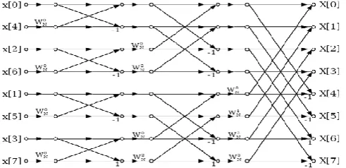
III.FAST FOURIER TRANSFORM
Before going further to inspect on the FFT and IFFT diagram, it respects clear up a bit on the speedy Fourier change and turn around snappy Fourier change activity. The snappy Fourier change (FFT) and inverse speedy Fourier change (IFFT) are gotten from the key limit which is called Discrete Fourier Transform (DFT). Utilizing FFT/IFFT as opposed to DFT is that the figuring of the limit can be made speedier where this is the central criteria for use in the automated flag taking care of. In DFT the count for N-motivation behind the DFT will figure one by one for each point. While for FFT/IFFT, the estimation is done in the meantime and this strategy saves a lot of time. The accompanying is the condition (2.2) showing the DFT and from here the condition is resolved to get FFT/IFFT limit.
N k j N n
e
n
x
k
X
2 1 0)
(
)
(
(1)X (k) represent the DFT frequency output at the k-the spectral point where k ranges from 0 to N-1. The quantity N
represents the number of sample points in the DFT data frame.
The quantity x (n) represents the nth time sample, where n also ranges from 0 to N-1. In general equation, x (n) can be real or complex.
The DFT equation can be re-written equation (2) into:
nk N N n
W
n
x
k
X
1 0)
(
)
(
(2)The quantity
W
Nnk is defined as in equation (3)N k j nk N
e
W
2
(3)Here is the place the riddle lies among DFT and FFT/IFFT where the condition limit above is called Twiddle Factor. This part is determined and put in a table remembering the ultimate objective to make the estimation less requesting and can keep running in the meantime. The Twiddle Factor table is depending upon the amount of point utilize. In the midst of the figuring of IFFT, the variable does not to recalculate since it can imply the Twiddle component table in this manner it save time since calculation is done at the same time.
Inverse Fast Fourier Transform
Table 1: Twiddle factor for 8 point inverse fast Fourier transform IFFT (N=8)
nk W Value
1 0
8
W
12 1
8
W
0.7071+j0.70713 2
8
W
j4 3
8
W
-0.7071+j0.70715 4
8
W
-16 5
8
W
-0.7071-j0.70717 6
8
W
-j18 7
8
W
0.7071-j0.7071IFFT is defined as the equation (4) below:
nk N N
n
W
k
X
N
n
x
10
)
(
1
)
(
(4)
Same FFT calculation can be utilized to discover IFFT capacity with the adjustments in specific properties. The progressions that actualize is by including a scaling component of 1/N and supplanting twiddle variable worth ( ) likewise can be utilized for the opposite quick Fourier change. The following is the table 1 demonstrates the estimations of twiddle component for IFFT.
IV.PROPOSED METHOD
DIT butterfly includes an augmentation took after by increases. As appeared in Table I the calculation time of fixed-point augmentation took after by an expansion am not as much as that of expansion took after by an increase. The DIT-based FT butterfly in this manner includes less engendering delay than that of DIF-based RFFT butterfly albeit both these butterflies include the same number of multipliers and adders. In this manner, the decision of DIT calculation to determine FT structure has preference over DIF calculation. In this paper, we exhibit efficient engineering for the DIT radix-2 RFFT calculation
V.FIR FILTER
If the coefficients are close to nothing, it is outstandingly beneficial to recognize through the rich structure of FPGA LUT. While the coefficient is considerable, it will take package of limit resources of FPGA and diminishing the tally speed. At that point, the N-1 cycles similarly realize too long LUT time and low enrolling speed. Shunwen Xiao, Yajun Chen, presented a change and headway of the DA figuring going for the issues of the course of action in the coefficient of FIR channel, the limit resource and the finding out speed, which influence the memory to estimate tinier and the task speed speedier to upgrade the computational execution.
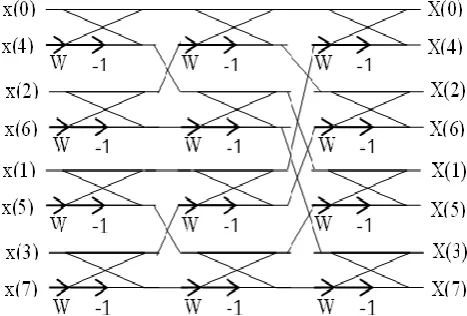
Figure 3: Radix-2 Decimation in Frequency Domain FFT Algorithm
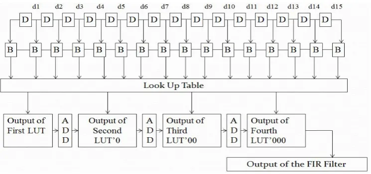
Figure 6: FIR Filter using Distributive Arithmetic Technique
Example:-
Step 1:- x(n) = 0001, where x(n) is the input of the FIR Filter Step 2:- x(n) is passing through all delay flip flop (D-FF),
d1= 0001, d2=0010, d3=0011, d4=0100, d5=0101, d6=0110, d7=0111, d8= 1000, d9=1001, d10=1010, d11=1011, d12=1100, d13=1101, d14=1110, d15=1111
Step 3:- Input of the FIR filter and output of the D-FF passing through Buffer
Step 4:- All buffer passing through LUT then
Output of the LUT
Suppose
h0=0000, h1=0001, h2=0010, h3=0011, h4=0100, h5=0101, h6=0110, h7=0111, h8=1000, h9=1001, h10=1010, h11=1011, h12=1100, h3=1101, h14=1110, h15=1111
So,
P1= 1000000 P2= 1000100 P3= 1001110 P4= 1011100 Step 5:- Output of the FIR Filter
Yn = P1 + P2’0 + P3’00 + p4’000
= 1000000 + 1000100’0 + 1001110’00 + 1011100’000 = 10011111000 (1240)
VI.SIMULATION RESULT
All the arranging and examination concerning figuring that we have determined in this paper is being made on Xilinx 14.2i updated variation. Xilinx 14.2i has couple of the striking components, for instance, low memory need, snappy examining, and insignificant exertion. The latest entry of ISETM (Integrated Software Environment) diagram gadget gives the low memory need unpleasant 27 rate low. ISE 6.1i that gives moved mechanical assemblies like astute consolidate advancement with better usage of their figuring gear gives snappier arranging conclusion and higher nature of results for a better time than laying out game plan. An ISE 14.2i Xilinx instrument gives more conspicuous flexibility for diagrams which impact embedded processors. In like manner included is the most current entry of the chip scope Pro Serial IO Tool pack, giving streamlined investigating of quick serial IO gets ready for Virtex-7 FX and Virtex-7 LXT and SXT FPGAs. With the help of this instrument we can make in the domain of correspondence and furthermore in the locale of sign planning and VLSI low power sketching out.
Table II: Simulation Result of IFFT and FIR Filter in UFMC Transmitter Block for Vertex-2p Device Family
IFFT using Radix-2 Butterfly Number of
Slice
Number of LUTs
MCPD (nsec) 8-Point IFFT 97 192 15.598
16-Point IFFT 260 512 19.260
32-point IFFT 656 1280 22.806
64-point IFFT 1536 3072 26.319
FIR Filter Number of
Slice
Number of LUTs
Maximum Frequency 8-tap FIR Filter 2841 5119 919.118 MHz
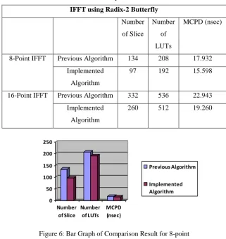
Table III: Comparison Result
IFFT using Radix-2 Butterfly
Number
of Slice
Number
of
LUTs
MCPD (nsec)
8-Point IFFT Previous Algorithm 134 208 17.932
Implemented
Algorithm
97 192 15.598
16-Point IFFT Previous Algorithm 332 536 22.943
Implemented
Algorithm
260 512 19.260
0 50 100 150 200 250
Number of Slice
Number of LUTs
MCPD (nsec)
Previous Algorithm
Implemented Algorithm
Figure 6: Bar Graph of Comparison Result for 8-point
0 50 100 150 200 250
Number of Slice
Number of LUTs
MCPD (nsec)
Previous Algorithm
Implemented Algorithm
Figure 7: Bar Graph of Comparison Result for 16-point
VII. CONCLUSION
point and number of subcarriers in a recurrence square. Limited Impulse Response channel assumes a critical part in numerous Digital Signal Processing applications. In this technique, the multiplier less FIR channel is actualized utilizing Distributed Arithmetic which comprises of Look Up Table and after that apportioning is included. This design gives a proficient zone time control usage which includes essentially less dormancy and less territory defer many-sided quality when contrasted and existing structures for FIR Filter.
REFERENCES
[1] Atif Raza Jafri, Javaria Majid, Muhammad Ali Shami, Muhammad Ali Imran And Muhammad Najam-ul-islam, “Hardware Complexity Reduction in Universal Filtered Multicarrier Transmitter Implementation”, IEEE Transaction of Wireless Communication, Vol. 34, No. 05, 2017.
[2] Basant Kumar Mohanty, and Pramod Kumar Meher, “High-Performance FIR Filter Architecture for Fixed and Reconfigurable Applications”, IEEE Transactions on Very Large Scale Integration (VLSI) Systems, Vol. 78, No.06, April 2016.
[3] Deepak Kumar Patel, Raksha Chouksey and Dr. Minal Saxena, “Design of Fast FIR Filter Using Compressor and Carry Select Adder”, 3rd International Conference on Signal Processing and Integrated Networks (SPIN), IEEE 2016.
[4] K. Durga and Mrs. A. Sivagam, “Efficient Adaptive RLFIR Filter based on Distributed Arithmetic Logic Using Reversible gates”, International Conference on IEEE 2016.
[5] Indranil Hatai, Indrajit Chakrabarti, and Swapna Banerjee, “An Efficient VLSI Architecture of a Reconfigurable Pulse-Shaping FIR Interpolation Filter for Multi-standard DUC”, IEEE Transactions on Very Large Scale Integration (VLSI) Systems, Vol. 23, No. 6, June 2015.
[6] S. Padmapriya and Lakshmi Prabha V., “Design of a power optimal reversible FIR filter for speech signal processing”, International Conference, pp. 01-06, ICCCI 2015.
[7] Kiran Joy and Binu K Mathew, “Implementation of a FIR Filter Model using Reversible Fredkin Gate”, Control, Instrumentation, Communication and Computational Technologies (ICCICCT), International Conference on IEEE Xplore, 22 December 2014.
[8] Ravi H Bailmare, S. J. Honale And Pravin V Kinge, “Design And Implementation of Adaptive FIR Filter using Systolic Architecture”, In International Journal of Current Engineering And Technology , Vol.4, No.3, June 2014.
[9] M. Usha, R. Ramadoss, “An Efficient Adaptive Fir Filter Based On Distributed Arithmetic”, International Journal of Engineering Science Invention, Vol. 3, Issue. 4, pp. 15-20, April 2014.