ISSN(Online): 2319-8753 ISSN (Print): 2347-6710
I
nternational
J
ournal of
I
nnovative
R
esearch in
S
cience,
E
ngineering and
T
echnology
(A High Impact Factor, Monthly, Peer Reviewed Journal)
Visit: www.ijirset.com
Vol. 8, Issue 3, March 2019
IOT Based Smart Prepaid Energy Metering
System to Control the Electricity Theft with
APFC and Stabilization Method
M.G.Anand1, K.Ranjitha2 , I.Sangeetha2 , A.Kalpana2
AP/EEE, Department of EEE, The Kavery Engineering College, Mecheri, Salem, Tamilnadu, India1
UG Scholar, Department of EEE, The Kavery Engineering College, Mecheri, Salem, Tamilnadu, India2
ABSTRACT: In this paper discuss pilferage of Electricity in the conversion of fraud (meter tampering), billing irregularities, stealing (illegal connections), and unfairness of bills. So in this paper used for prepaid energy metering system to control the power theft. A smart prepaid energy metering system is installed in every consumer unit and a server is maintained at the details through service provider side. Both the meter and the server are equipped with IOT module which facilitates bidirectional communication. Consumers can easily recharge their energy meter through mobile application. And also provide the automatic power factor correction and Stabilization concept to be added. Because of the domestic system for equipment to take the excess voltage and excess current, then efficiency will be reduced. In this paper used to know how much amounts of power consumed at daily updates, internal and external theft identification to be displayed and sending message for the users and government.
KEYWORDS: electricity theft; prepaid meter; GSM networks; SMS; smart energy meter, IOT, PF–Power Factor; A.P.F.C–Automated Power Factor Correction; Emonlib–Energy Monitoring Library ;C.T–Current Transformer; P.T– Potential Transformer.
I. INTRODUCTION
Electricity plays a vital role in growth of our country. Even though power production corporations focusing highly on generation, transmission and distribution, they are meeting power loss due to illegal consumption of electrical power from the transmission lines by the consumers. Power theft has become a great challenge to the electricity board. The dailies report says that Electricity Board suffers a total loss of 8 % in revenue due to power theft every year, which has to be controlled. This research paper identifies the power theft and indicates it to the Electricity board through Wi-fi network. It also deals about the remote monitoring of an energy meter in the proposed system. In the field of electrical or electronics current and energy consumption, which may effect on stabilization of the components, are playing an important role. In case of Industries, the industrialists have to monitor and control the usage of electrical energy level. The main objective is to prevent energy usage beyond the maximum allotted energy by the power supplier, by preventing from over load usage. Energy consumption is audited by using current transformer connected series to the load.
ISSN(Online): 2319-8753 ISSN (Print): 2347-6710
I
nternational
J
ournal of
I
nnovative
R
esearch in
S
cience,
E
ngineering and
T
echnology
(A High Impact Factor, Monthly, Peer Reviewed Journal)
Visit: www.ijirset.com
Vol. 8, Issue 3, March 2019
II. LITERATURE SURVEY
In 2010, using Multi-appliance power disaggregation technology implementers implemented the linear detection algorithm to determine which appliances are active in their power contributions. Problems are robust to errors in this database .[5] In 2011, using cloud computing technology found the solution for efficiency calculation of individual equipment.[4] In 2012, using three feedback system, monitored the energy in residential Real-Time. It is critical to the continuing engagement and use of the device to save energy. Residences to determine the feedback provided by real-time energy monitors results in lower residential consumption rates during the 30 days after installation. [6] . 1n 2014, GSM technology implemented automatic power will be reading. [1]. In 2016. Using wifi technology application can develop for Apple and BlackBerry 10 OS, thus providing multiple platform users support [2] . In 2017, using IOT technology An IoT device was created for measuring the voltage, current, power and energy of a three-phase four-line power four-line in a laboratory building [3]
III. DESIGN METHODOLOGY
The whole APFC unit consists of eight modules. They collectively work together to gain a power factor correction. These modules are given as follows:
o Power supply. o Voltage sensor circuit. o Current sensor circuit. o Microcontroller. o Inductive load network. o Relay driver.
o Display. o Capacitor Bank.
MICRO CONTROLLER EB/AC
POWER
SUPPLY RECTIFIER
REGULATED POWER SUPPLY
CT/PT
RFID READER
LCD DISPLAY
WI-FI NETWORK
Fig.1.Block Diagram of energy metering system
A. Power supply:
ISSN(Online): 2319-8753 ISSN (Print): 2347-6710
I
nternational
J
ournal of
I
nnovative
R
esearch in
S
cience,
E
ngineering and
T
echnology
(A High Impact Factor, Monthly, Peer Reviewed Journal)
Visit: www.ijirset.com
Vol. 8, Issue 3, March 2019
Fig. 2.Power supply circuit diagram
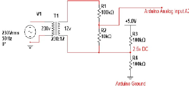
B. Voltage sensor circuit
The mains230v AC is stepped down to 12v AC. A voltage divider circuit divides this 12v in 1:10 ratio, which provides around 1.2vsinusoid signal. A DC offset of 2.5v is applied to the sinusoidal signal. As a result the whole sinusoid can be observed in the positive boundary (0-5v) and the microcontroller can read the whole sinusoid signal through its analog input. The circuit diagram of the voltage sensor circuit is shown below [7]
Fig. 3.voltage sensor circuit diagram
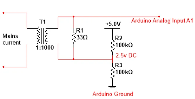
C. Current sensor circuit
ISSN(Online): 2319-8753 ISSN (Print): 2347-6710
I
nternational
J
ournal of
I
nnovative
R
esearch in
S
cience,
E
ngineering and
T
echnology
(A High Impact Factor, Monthly, Peer Reviewed Journal)
Visit: www.ijirset.com
Vol. 8, Issue 3, March 2019
Fig. 4 Current sensor circuit diagram
D. Microcontroller
A microcontroller is a small computer on a single integrated circuit containing processor core, memory, and programmable input/output peripherals [8].An PIC microcontroller (PIC16F877A)is used in this project, which has lots of libraries developed and available online for free. A program was developed for calculation and automatic actions of the project and burned on the microcontroller using PIC16F877A. Mains voltage, mains current, real power, apparent power and power factor of the network are calculated through the developed program [9-11].
E. Inductive load network
The inductive load network is a combination of loads having inductive characteristics and consuming huge electrical power due to lagging power factor. The network collectively simulates a highly inductive load operating at a very poor power factor.
F. Relay drivers
The loads and capacitors are connected to a high voltage circuit. In order to incorporate these high voltage components with microcontroller relay is used for switching operation on capacitors in high voltage circuit through the control signal from microcontroller keeping the microcontroller safe and electrically isolated from high voltage [12].
G. Display
The calculated power parameters current power factor, mains voltage, mains current, real and apparent power are continuously displayed on a 20x4 Liquid Crystal Display monitor. [9][11].
H. Capacitor Bank
ISSN(Online): 2319-8753 ISSN (Print): 2347-6710
I
nternational
J
ournal of
I
nnovative
R
esearch in
S
cience,
E
ngineering and
T
echnology
(A High Impact Factor, Monthly, Peer Reviewed Journal)
Visit: www.ijirset.com
Vol. 8, Issue 3, March 2019
Fig.5.Hardware proto type
IV. TECHNICAL DESIGN
The technical design of the system can be described in four main steps, namely, Emonlib library inclusion, calibration of Emonlib, KVAR calculation, and capacitor switching.
A. Emonlib library inclusion
Emonlib is an open source library developed for energy monitoring purpose. The Emonlib library is capable of reading analog voltage and current signals and it can calculate the mains voltage, mains current, real power, reactive power, apparent power and power factor. The built in methods of the library are provided by the Emonlib developers which can be used in order to retrieve required power parameters mentioned above [7].
B. Calibration process
Some factors are needed to be determined based on the components used in the voltage and current sensor circuits. These factors values are put as the arguments of Emonlib methods for accurate power calculations. Voltage and current calibration constants are determined based on the step down and voltage divider ratios of PT and CT. For the developed APFC system the voltage and current calibration constants are determined as 184 and 1.5 respectively. The phase calibration constant 1 gives no phase correction and the values 0 and 2
provide 7° of correction in opposite direction. The exact phase calibration is done using pure resistive load and adjusting the phase constant until power factor measured is 1.0 [7].
C. Required KVAR Calculation
The calculated power parameters are used to determine the required KVAR. If the current power factor is COSφ1 and targeted power factor is cosφ2then,
Required KVAR = P (tanφ1 − tanφ2)
Capacitance in Farad, C = (VAR/2 fV2 )
Where, P = Real power in KW, f is the frequency and V is the voltage of the power system [13].
D. Capacitor Switching
The microcontroller itself takes the decision of required KVAR demand and automatically switches the capacitors of desired value from the capacitor bank. Multiple channel relay module is used to perform this switching action.
V. RESULT
ISSN(Online): 2319-8753 ISSN (Print): 2347-6710
I
nternational
J
ournal of
I
nnovative
R
esearch in
S
cience,
E
ngineering and
T
echnology
(A High Impact Factor, Monthly, Peer Reviewed Journal)
Visit: www.ijirset.com
Vol. 8, Issue 3, March 2019
supply line will be disconnected. Using Wi-Fi technology is more advantageous for both user side and provider side. There is no need to go at consumer side to disconnect the supply line, using IOT it can be monitored by online only.
VI. CONCLUSION AND FUTURE SCOPE
Energy monitoring through the internet is easy. It gives the real power consumption as well as accurate reading. Also, it requires fewer labors and less time to monitor the energy. It can transmit the data to the utilities and also can receive information from utilities. After two months electricity bill will be paid otherwise supply line will be disconnected through the internet. After two months validity for alert purpose buzzer will be ON. It is easy to know the two months validity. By making this thing the energy will be monitored. The future scope will be on PC side one server software is required for automatic data collection. In this project, HTML knowledge is taken for demonstration purpose..
REFERENCES
[1] Nabil Mohammad,, Anomadarshi Barua.et,al " A Smart Prepaid Energy Metering System to Control Electricity Theft” .International Conference on Power, Energy and Control (ICPEC,2017
[2]Yasin Kabir,Yusuf Mohammad Mohsinand,et al. "Automated Power Factor Correction and Energy Monitoring System” International Conference on. IEEE, 2017
[3] Islam, Md Manirul, et al. "Electronic energy meter with remote monitoring and billing system." Electrical & Computer Engineering (ICECE), 2012 7th International Conference on. IEEE, 2012.
[4] Chandel, Priyamvada, Tripta Thakur, and B. A. Sawale. "Energy Meter tampering: Major cause of non-technical losses in Indian distribution sector." Electrical Power and Energy Systems (ICEPES), International Conference on. IEEE, 2016.
[5] Islam, Md Sajedul, and Md Sadequr Rahman Bhuiyan. "Design and implementation of remotely located energy meter monitoring with load control and mobile billing system through GSM." Electrical, Computer and Communication Engineering (ECCE), International Conference on. IEEE, 2017.
[6]_Ramadan, Kamal, Elfadil Zakaria, and Dalia M. Eltigani. "Prepaid energy meters network via power system communication." Computing, Electrical and Electronics Engineering (ICCEEE), 2013 International Conference on. IEEE, 2013.
[7]_Zhang, Daqiang, Hongyu Huang, and Minho Jo. "Future RFID technology and applications: visions and challenges." Telecommunication Systems (2014): 1-2.
[8]_Klaus Finkenzeller, RFID Handbook: Fundamentals and Applications in Contactless Smart Cards and Identification, Second Edition, Wiley, 2003.