Copyright to IJIRSET DOI:10.15680/IJIRSET.2019.0805049 5181
Area Efficient VLSI Architecture for FFT
using radix-2 Butterfly and Folding Technique
Riya Jain1, Dr. Vibha Tiwari2
M. Tech. Scholar, Department of Electronics & Communication Engineering
,
Technocrats Institute of Technology,Bhopal, India1
Professor, Department of Electronics & Communication Engineering
,
Technocrats Institute of Technology,Bhopal, India 2
ABSTRACT: The Discrete Fourier Transform (DFT) is an important technique in the field of Digital Signal Processing (DSP) and Telecommunications, especially for applications in Orthogonal Frequency Division Multiplexing (OFDM) systems. The Fast Fourier Transform (FFT) is an efficient algorithm to compute the DFT and its inverse. The FFT processor plays a key role in the field of communication systems such as Digital Video or Audio Broadcasting, Wireless LAN with Standards of IEEE 802.11, High Speed Digital Subscriber Lines etc. In this paper involves the implementation of a area efficient 8-point, 16-point, 32-point, 64-point and 128-point single path delay feedback (SDF) and folding technique using radix-2 DIT FFT algorithm. The proposed algorithm are used in radix-2 butterfly in all stage. The proposed algorithm is area efficient and consumed delay in previous algorithm. The all design are implementation vertex-2p device family Xilinx software.
KEYWORDS: FFT, Folding Technique, Single Path Delay Feedback (SDF), Serial in Serial out Shift Register
I. INTRODUCTION
The Fourier Transform is an inevitable approach in signal processing, particularly for applications in Orthogonal Frequency Division Multiplexing (OFDM) systems [1]. The Discrete Fourier Transform decomposes a set of values into different components of frequency. The Fast Fourier transform (FFT) is an appropriate technique to do manipulation of DFT. The algorithm of FFT was devised by Cooley and Tukey in order to decrease the amount of complexity with respect to time and computations [2].
computation is concerned. Generally DIT deals with the input and output in reverse sequence and normal sequence respectively, while DIF deals with input and output in normal sequence and reverse sequence respectively. Only Decimation-in-frequency (DIF) algorithm will be taken into consideration.
II. FAST FOURIER TRANSFORM
There are two types with respect to FFT algorithm devised by Cooley and Tukey - Decimation-in-Time algorithm (DIT) and Decimation-in-Frequency algorithm (DIF). The computation of a sequence of N-point can be obtained by means of a dual approach. The input sequence x(n) of size ‘N’ is decomposed into samples of odd and even and the corresponding sub-sequences f1(n) and f2(n) are given by:
f
1(
n
)
x
(
2
n
)
(1)
1
2
...
...
1
,
0
),
1
2
(
)
(
1
N
n
n
x
n
f
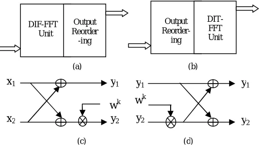
(2) DIF-FFT Unit Output Reorder -ing Output Reorder-ing DIT-FFT Unit x1 x2 y1 wk y2 y1 wk y2 y1 y2(a) (b)
(c) (d)
Copyright to IJIRSET DOI:10.15680/IJIRSET.2019.0805049 5183
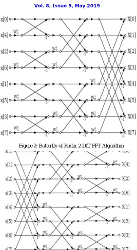
In figure 2, show the butterfly of radix-2 DIT FFT algorithm. In this figure we used eight inputs and eight outputs. In case of DIT the input sample is used bit reversal order while the output of DIT FFT coefficients is generated in natural order. In Figure 3, show the butterfly of radix-2 DIF FFT algorithm. In case of DIF the input sample is used in natural order while the output of DIF FFT coefficient is generated in bit reversed order.
Figure 2: Butterfly of Radix-2 DIT FFT Algorithm
III. PROPOSED METHODOLOGY
In proposed method are used in binary input is going to the serial input serial output (SISO) shift register as shown in Figure 4. In proposing algorithm consist of SISO, different types of multiplier, Kogge stone (KS) adder, subtractor, single path delay feedback (SPD) pipeline and folding architecture.
SISO: - SISO technique depends on the binary input. Suppose the binary input of the system is 8 word length, then eight delay flip flops are used in SISO register.
Different types of Multiplier:- there are three types of multiplier are used in proposed algorithm, i.e. array multiplier, sign (Baugh) multiplier and complex multiplier. Another name of array multiplier is binary unsigned multiplied.
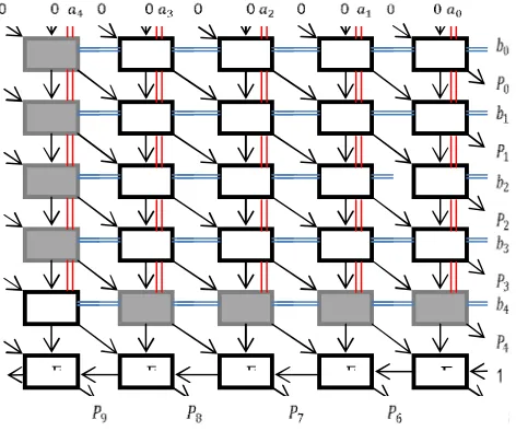
The Baugh - Wooley algorithm for the signed binary multiplication is based on the concept shown in figure 5. The algorithm specifies that all possible AND terms are created white cell and all possible NAND terms are created gray cell. The white cell consists of full adder and AND gate, but the gray cell consists of full adder and NAND gate.
Figure 4: Flow Chart of Proposed Algorithm
F F F F
Copyright to IJIRSET DOI:10.15680/IJIRSET.2019.0805049 5185
Complex multiplication is consisting of 4 multiplications, 2 adders and 1 subtraction. But in the proposed complex multiplication is consisting of 3 multiplications, 1 adder and 1 subtraction in shown in figure 6.
Figure 6: Block Diagram of Complex Multiplication
Subtractor:- Subtractor is consist of half subtractor and full subtractor depends on word length in proposed algorithm. KS adder:- Input sequence of Conventional method is much more than to proposed method, however proposed method has less propagation delay. Area and propagation delay can be reduced by the aid of proposed kogge stone (KS) adder. This adder will be designed like as ripple carry adder. Carry output of one KS adder is connected with another KS adder but this method is very beneficiary for high efficient digital devices as per concerning propagation delay.
Figure 7: A Proposed 2 bit KS Adder
Figure 8: Flow Graph of the Radix-2 SDF Pipeline Architecture
Folding Architecture:- Folding is a transformation technique using in DSP architecture, implementation for minimizing the number of functional blocks in synthesizing DSP architecture. Folding was first developed by Keshab K. Parhi and his students in 1992.
IV. SIMULATION RESULT
The simulation results for various FFT algorithms have been tested practically by implementing in the Vertex-2p Xilinx software. Also these software outputs can be verified with simulation results obtained using MODELSIM. Some of the snapshots of results in the Xilinx software and simulation are as follows
Figure 9: (a) Without folding technique (b) With folding technique
Figure 10: Proposed DIT Radix-2 FFT algorithm using Radix-2 Butterfly
Copyright to IJIRSET DOI:10.15680/IJIRSET.2019.0805049 5187
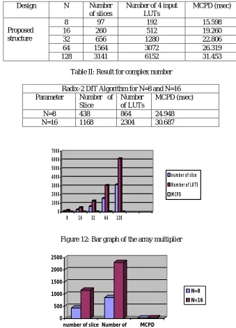
Table I: Show the result for proposed algorithm in array multiplier with Vertex-2p device family
Table II: Result for complex number
Radix-2 DIT Algorithm for N=8 and N=16
Parameter Number of
Slice
Number of LUTs
MCPD (nsec)
N=8 438 864 24.948
N=16 1168 2304 30.687
0 1000 2000 3000 4000 5000 6000 7000
8 16 32 64 128
number of slice
Number of LUTS
MCPD
Figure 12: Bar graph of the array multiplier
0 500 1000 1500 2000 2500
number of slice Number of LUTS
MCPD
N=8 N=16
Figure 13: Bar graph of the complex multiplier
Design N Number
of slices
Number of 4 input LUTs
MCPD (nsec)
Proposed structure
8 97 192 15.598
16 260 512 19.260
32 656 1280 22.806
64 1564 3072 26.319
V. CONCLUSION
The Fast Fourier transformation (FFT) is a frequently used Digital signal processing (DSP) algorithms for the applications of Orthogonal Frequency Division multiplexing (OFDM). The combination of Orthogonal Frequency Division Multiplexing (OFDM) with Multiple Input Multiple Output (MIMO) signal processing is a definite approach of enhancing the data rates of various communication systems such as Wireless LAN, e Mobile, 4G etc.
Since FFT processor is a complex module in OFDM, it is highly inevitable to design the processor in an efficient way. This research work involved the implementation of a low delay and area efficient 128-point pipelined FFT processor using radix-2 algorithm. The proposed algorithm is about 14- 15% consumed de in existing algorithm.
REFERENCES
[1] Charles. Roth Jr., “Digital Systems Design using VHDL”, Thomson Brooks/Cole, 7th reprint, 2005.
[2] S. S. Kerur, Prakash Narchi, Jayashree C N, Harish M Kittur and Girish V A, “Implementation of Vedic multiplier for Digital Signal Processing”, International Conference on VLSI, Communication & Instrumentation (ICVCI) 2011, Proceedings published by International Joural of Computer Applications® (IJCA), pp.1-6.
[3] Himanshu Thapaliyal and M.B Srinivas, “VLSI Implementation of RSA Encryption System Using Ancient Indian Vedic Mathematics”, Center for VLSI and Embedded System Technologies, International Institute of Information Technology Hyderabad, India.
[4] Jagadguru Swami Sri Bharati Krishna Tirthaji Maharaja, “Vedic Mathematics: Sixteen simple Mathematical Formulae from the Veda”, Delhi (2011).
[5] Harpreet Singh Dhillon and Abhijit Mitra, “A Reduced-bit Multiplication Algorithm for Digital Arithmetic”, International Journal of Computational and Mathematical Sciences, Febrauary 2008, pp.64-69.
[6] Sumit Vaidya and Depak Dandekar. “Delay-power performance comparison of multipliers in VLSI circuit design”. International Journal of Computer Networks & Communications (IJCNC), Vol.2, No.4, July 2010.
[7] Pramod Kumar Mehe, Basant Kumar Mohanty, Sujit Kumar Patel, Soumya Ganguly, and Thambipillai Srikanthan, “Efficient VLSI Architecture for Decimation-in-Time Fast Fourier Transform of Real-Valued Data”, IEEE Transactions on Circuits And Systems—I: Regular Papers, Vol. 62, No. 12, December 2015.
M. Ayinala, Y. Lao, and K. K. Parhi, “An in-place FFT architecture for real-valued signals,” IEEE Trans. Circuits Syst. II, Exp. Briefs, vol. 60, no. 10, pp. 652–656, Oct. 2013.
[8] Shashank Mittal, Md. Zafar Ali Khan and M.B. Srinivas, “Area Efficient High Speed Architecture of Bruun’s FFT for Software Defined Radio”, 1930-529X/07/$25.00 © 2007 IEEE.