Design Optimization of Planner Machine
Mechanism
Rinoy Johnson K
1, Dr.S.Sankar
2, Rahul R
3,
Tedy Thomas
4PG Student, Dept. of Mechanical Engineering, Nehru College Of Engineering and Research Centre, Thrissur,
Kerala,India1
HOD, Dept. of Mechanical Engineering, Nehru college of engineering and Research Centre,Thrissur,Kerala,India2
Assistant Professor, Dept. of Mechanical Engineering, Nehru college of engineering and Research Centre, Thrissur,
Kerala, India3
Assistant Professor, Dept. of Mechanical Engineering, Nehru college of engineering and Research Centre, Thrissur,
Kerala, India4
ABSTRACT: A gear is a rotating machine part having teeth or cogs, which mesh with another toothed part in order to
transmit torque. In this project a defect existing in a planner machine is identified and new methods were used to reduce the effects of the existing defect. In the existing planner mechanism force required for the movement of the rack and pinion mechanism of the planner is transmitted through a shaft connected to the pinion. Thus when the cutting forces reach above a particular value the tooth of the spur gear gets broken. In order to rectify this defect a new mechanism using two bevel gears placed at right angles is used to transmit forces to the pinion and both the mechanisms are compared using Ansys 17.0 to evaluate the improvements in performance. Then the material of the modified design is optimized by comparing the performances of three different materials such as Grey cast iron, Stainless steel and AISI 4140.
KEYWORDS: Planer machine, Stainless steel, Bevel gear, AISI 4140
I. INTRODUCTION
II. DESIGNPROCEDURE
This section deals with the process of modeling. Model is a representation of an object, a system, or an idea in some form other than that of the entity itself. Modeling is the process of producing a model; a model is a representation of the construction and working of some system of interest. A model is similar to but simpler than the system it represents. Generally, a model intended for a simulation study is a mathematical model developed withthe help of simulation software. Softwares commonly used for modelling are SolidWorks, Creo, Catia, Unigraphics etc. In this project SolidWorks 2016 edition is used for the modelling process
.
Design of gear mechanism
Fig.1 Designed model Fig.2 Bevel gear
III. ANSYSPROCEDURE
This section deals with the analysis of the designed model. The model that is in STEP format is analysed. Static structural analysis of both stabilizer bar link and suspension system is performed by applying the working load and number of supports used is two. The model is imported to Ansys and meshing is performed. The mesh size used is 4.4 mm. From the results obtained optimal design is selected. Suitable materials are applied to three different models of stabilizer bar link and modal analysis is performed. Different softwares such as Comsol, Radioss solver, Abaqus, Hypermesh, Ansys etc. are used for analysis. In this project Ansys R15.0 is used for design analysis.
Design Analysis of existing design
Fig.3 Meshed model of existing design Fig.4 Analysis setup of the existing design
Table 1 Overview of analysis results of existing design
Table 1 above repressents the total deformation,equivalent elastic strain,equivalent stress and normal stress of the existing design.
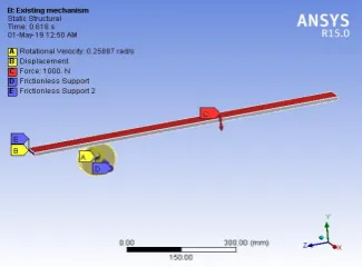
Design analysis of modified design.
The figure shown below represents the analysis setup and total deformation of modified design.
Property Max Min
Total deformation
(mm) 0.25322 0
Equivalent elastic
strain 0.003453 8.3543e
-8
Equivalent stress
(MPa) 359.77 0.0015714
Fig.6 Analysis setup of modified design Fig.7 Total deformation of the modified design
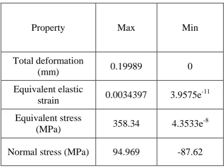
Table 2 Overview of analysis results
Property Max Min
Total deformation
(mm) 0.19989 0
Equivalent elastic
strain 0.0034397 3.9575e
-11
Equivalent stress
(MPa) 358.34 4.3533e
-8
Normal stress (MPa) 94.969 -87.62
Table 2 above repressents the total deformation,equivalent elastic strain,equivalent stress and normal stress of the modified design. From the analysis results it can be concluded that themodified design have the least value of maximum total deformation. Hence the modified design is selected as the best suitable system.
IV. MATERIAL OPTIMISATION
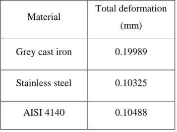
Table 3 Summary of analyses results of modified design applied with different materials
Material Total deformation (mm)
Grey cast iron 0.19989
Stainless steel 0.10325
AISI 4140 0.10488
From Table 3 it can be clearly understood that stainless steel exhibits the least value of total deformation among the three materials selected for comparison. Hence stainless steel is selected as the final material of the modified design.
V. RESULTSANDDISCUSSION
Fig. 8 Variation in the total deformation values of both the designs
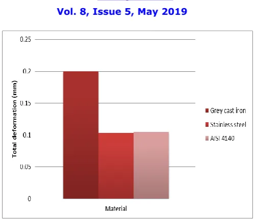
Fig 9 Comparison of total deformation values of different materials
Hence, modified chassis applied with stainless steel will reduce the total deformation from 0.25322 to 0.10325. The percentage reduction in total deformation is 59.22% as compared to the existing design.
VII.CONCLUSION
In this project the rack and pinion mechanism of a planner machine has been optimised by using an arrangement consisting of two bevel gears. Then the design was modified and the force is transmitted through a set of bevel gears onto the pinion. This has reduced the total deformation value from 0.25322 mm to 0.19989 mm. Also different characteristic properties of both the mechanisms such as equivalent stress, equivalent elastic strain, normal stress and normal elastic strain were analysed and results were compared. From these results it is clear that the new mechanism is a significantly better mechanism as compared to the older mechanism. Then three different materials such as Grey cast iron, Stainless steel and AISI 4140 were applied and the total deformation values were compared. It was found out that the modified design applied with stainless steel has the least value of total deformation.
REFERENCES
[1] H.N. Özgüven , D.R. Houser , Mathematical models used in gear dynamics-a review, J. Sound Vib. 121 (3) (1988) 383–411.
[2] C.S. Hsu , W.H. Cheng , Steady-state response of a dynamical system under combined parametric and forcing excitations, J. Appl. Mech. 41 (2) (1974) 371–378
[3] M. Benton , A. Seireg , Simulation of resonances and instability conditions in pinion- gear systems, J. Mech. Des. 100 (1) (1978) 26–32.
[4] R.G. Munro , The dynamic behaviour of spur gears, Cambridge University, 1962 Ph.D. thesis .