ISSN(Online): 2319-8753 ISSN (Print): 2347-6710
I
nternational
J
ournal of
I
nnovative
R
esearch in
S
cience,
E
ngineering and
T
echnology
(A High Impact Factor, Monthly, Peer Reviewed Journal)
Visit: www.ijirset.com Vol. 8, Issue 1, January 2019
Design of PID Controller through Op-Amp
Realization
Badat Ismail Yusuf1, Patel Safvan Harun2, Abdul Mannan Kagzi3 , Richa Dubey 4
U.G. Student, Department of Electrical Engineering, SRICT, Vataria, India1 U.G. Student, Department of Electrical Engineering, SRICT, Vataria, India2 U.G. Student, Department of Electrical Engineering, SRICT, Vataria, India3 Assistant Professor, Department of Electrical Engineering, SRICT, Vataria, India4
ABSTRACT: The PID control is the most commonly known for control process utilized as a part of industries for
controlling action. The basic technique for PID controllers makes it simple to coordinate the process output. As the term PID suggest, it comprises of three separate constant parameters which are adjusted in order to get ideal, steady and faster response. In the control process, the majority of control loops based upon proportional, integral and derivative controller. For specific process, the tuning of three parameters of controller is able to provide specific control action to the system. Design methods leading to an optimal and effective operation of PID controllers are economically vital for process industries. The main focus of the project is about study of OP-AMP and fabrication of an analog PID Controller using the three control parameters. The Controller design is demonstrated through simulation in order to get an output of better dynamic and static performance. The controller is fabricated on hardware after the test of individual terms:-proportional, integral and derivative. The resultant output from controller is observed using the oscilloscope.
KEYWORDS: PID Controller, Op-Amp, Simulation , Oscilloscope
I. INTRODUCTION
Proportional-Integral-Derivative (PID) controllers are one of the most commonly used types of controllers. They have numerous applications relating to temperature control, speed control, position control, etc. A PID controller provides a control signal that has a component proportional to the tracking error of a system, a component proportional to the accumulation of this error over time and a component proportional to the time rate of change of this error. This module will cover these different components and some of their different combinations that can be used for control purposes. The proportional, integral and derivative terms are summed to calculate the output of the PID controller. Defining U(t) as the controller output, the final form of the PID algorithm is given by
Where kp : Proportional gain
ki : Integral kd : Derivative gain, e : Error
ISSN(Online): 2319-8753 ISSN (Print): 2347-6710
I
nternational
J
ournal of
I
nnovative
R
esearch in
S
cience,
E
ngineering and
T
echnology
(A High Impact Factor, Monthly, Peer Reviewed Journal)
Visit: www.ijirset.com Vol. 8, Issue 1, January 2019
II. LITERATURE SURVEY
A proportional-integral-derivative controller is common feedback loop component.in industrial control system. The Controller compares a measured value from a process with a reference set point value. The difference is then used to calculate a new value for a manipulable input to the process that brings the process measured value back. to its desired set point. Unlike simpler control algorithms, the PID controller can adjust process outputs based on the history and rate of change of the error signal, which gives more accurate and stable control. It can be shown mathematically that a PID. loop will. Produce accurate, stable control in cases where a simple proportional control would either have a steady-state error or would cause the process to oscillate.
In a PID loop, correction is calculated from the error in three way cancel out the current error directly (Proportional), the amount of time the error has continued uncorrected (Integral), and anticipate the future error from the rate of change of the error over time (Derivative)
A control loop consists of three parts:
a). Measurement by a sensor connected to the process . b). Decision in a controller element.
c). Action through an output device such as an motor.
As the controller reads. a sensor, it subtracts this measurement from the "set point" to Determine the "error". It then uses the error to calculate a correction to the process's input Variable (the "action") so that this correction will remove the error from the process's Output measurement.
In a PID loop, correction is calculated from the error in three ways: cancel out the current error directly (Proportional), the amount of. time the error has continued uncorrected (Integral), and anticipate the future error from the rate of change of the error over time Derivative.
ISSN(Online): 2319-8753 ISSN (Print): 2347-6710
I
nternational
J
ournal of
I
nnovative
R
esearch in
S
cience,
E
ngineering and
T
echnology
(A High Impact Factor, Monthly, Peer Reviewed Journal)
Visit: www.ijirset.com Vol. 8, Issue 1, January 2019
I. P-D controller
Prediction of the behavior of error will always result in better stability. In order to avoid effects of the sudden change in load, the derivative of the error signal taken in this mode to predict the trend of a controlled variable. So let us see in detail, how does PD Controller work. lmost all physical processes have transportation lag (Dead Time) in their system (usually due to improper allocation of the sensor) since only proportional controller’s output will react after some time to sudden change in load and which may result in a huge transient error. But, with the addition of a derivative controller, this mode becomes capable of predicting error with consideration of dead time. So that, sudden jerks or spike signals are not given to actuator, hence improves the life span of actuators.
Applications
Level control:- Maintaining a level of liquid inside the tank is a sluggish and integrating process and many cases due to improper allocation of level sensor (in this case which is measured as a function of flow) result into the significant addition of transportation lag. PD controller mode has the capability to predict future of error, hence the effect of additional dead time is reduced. A sudden change in desired value of level will result in high overshoot in the case of PI control mode, but in the case of PD control mode, this integrating effect will be reduced by addition derivative term with the proportional term.
II. PID Controller
PID control stands for proportional plus derivative plus integral control. PID control is a feedback mechanism which is used in control system. This type of control is also termed as three term control. By controlling the three parameters - proportional, integral and derivative we can achieve different control actions for specific work. PID is considered to be the best controller in the control system family.
It gets the input parameter from the sensor which is referred as actual process variable. It also accepts the desired actuator output, which is referred as set variable, and then it calculates and combines the proportional, integral and derivative responses to compute the output for the actuator.
Application
Temperature controller - often called a PID controller is an instrument used to control temperature. The temperature controller takes an input from a temperature sensor and has an output that is connected to a control element such as a heater or fan. To accurately control process temperature without extensive operator involvement, a temperature control system relies upon a controller, which accepts a temperature sensor such as a thermocouple or RTD as input. It compares the actual temperature to the desired control temperature, or set point, and provides an output to a control element.
Speed control of DC motor.
IV. CHOICE OF CIRCUIT PARAMETERS
ISSN(Online): 2319-8753 ISSN (Print): 2347-6710
I
nternational
J
ournal of
I
nnovative
R
esearch in
S
cience,
E
ngineering and
T
echnology
(A High Impact Factor, Monthly, Peer Reviewed Journal)
Visit: www.ijirset.com Vol. 8, Issue 1, January 2019
Figure : Proportional controller
A sinusoidal signal voltage wave from the function generator is applied to the input of controller circuit. The amplitude of input voltage wave is 2 volts and frequency of 100kHz. The input and output voltage waveforms were observed in CRO. The results were noted and waveforms were traced in tracing paper or recorded. The experiment was repeated by varying the values of using potentiometer Now, we needed to do the same test with the derivative controller. Here, we needed to supply a ramp input and check the output. Since, ramp signal cannot be generated due to saturation, so, we used a triangular wave input to the controller. As we required 0<= <=10, we use a 10micro Farad capacitor, a 1K resistor and a 1M pot for the purpose, as shown in below circuit diagram. Waveforms were viewed in CRO.
Figure : Derivative controller
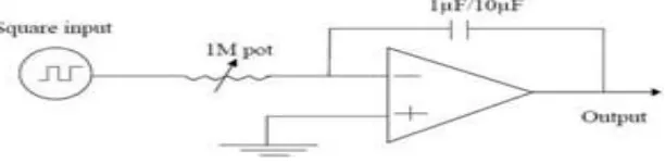
we repeated the test for integral controller with circuit diagram as shown below. Components required were 1 micro Farad capacitor and 1M pot and a small, resistance say 1kohm was put in series with the capacitor as shown in the circuit diagram above.
ISSN(Online): 2319-8753 ISSN (Print): 2347-6710
I
nternational
J
ournal of
I
nnovative
R
esearch in
S
cience,
E
ngineering and
T
echnology
(A High Impact Factor, Monthly, Peer Reviewed Journal)
Visit: www.ijirset.com Vol. 8, Issue 1, January 2019
After, the testing the all of the controller we proceed to fabricate our required PID controller according to the circuit diagram for design given below. The components are assembled, connection were made according to the circuit design on the bread board. The components used for the fabrication are described in table below
ParameterRise time OvershootSettling timeSteady- state errorStability
Kp Decrease Increase Small change Decrease Degrade
Ki Decrease Increase Increase Eliminate Degrade
Kd Minor change Decrease Decrease No effect in theory Improve if is small
In Proportional Controller the rise time decreases as well as in integral controller and there is a minor change in deriavative controller but overshoot time increases as well as for integral controller and overshoot time decreases.
V. CONCLUSION
We conclude that while performing proportional controller on kit we were not able to get exact reading and the controller overshoots the set point. As per the integrator in the circuit concerned, the response had a slow rise and decay time.
REFERENCES
[1].OPAMP realization and PID controller fabrication by Soumya Ranjan Kanhar.
[2].Bennett, Stuart (1993), A history of control engineering, (1930-1955), IET. P.48. ISBN 978-0-86341-299-8.
[3] Control System Engineering book by I.J Nagrath and Madan Gopal 5th edition by New Age International Publisher (2007)
[4] K. Astrom and T. Hagglund, “The future of PID control,” Control Engineering Practice, vol. 9, no. 11, pp. 1163 – 1175.
[5] P. Birkus. Controloflinearcontinuoussystems. Master Thesis, FEI STU, Slovak Republic, May 2012.
[6]LM741 Operational Amplifier Texas Instruments accessed on: LM741. SNOSC25D – MAY 1998–REVISED OCTOBER 2015 [7]Motor with Integral controller ,Patent Number:US51512198A
[8]System and method for variable gain Proportional Controller (PI) controller,Patent Number:US445980B1 [9]Pid Controller System,Patent Number:US4903192A
[10]Simple Realization of current mode and voltage mode PID,PI,PD Controllers conference paper published in February 2005,DOI:10.1109/ISIE.2005.1528911
[11]PID Control Theory by Kambiz Arab Tehrani and Augustin Mpanda published on 29,February,2012