Power Quality Improvement in Microgrid
Athira Vijay J1, Soumya . A.V2
P.G. Student, Department of Electrical and Electronics Engineering, Mar Baselious College of Engineering and
Technology, Trivandrum, Kerala, India1
Assistant Professor, Department of Electrical and Electronics Engineering, Mar Baselious College of Engineering and
Technology, Trivandrum, Kerala, India2
ABSTRACT: In this paper, a power quality controller suitable for microgrid is proposed, which can cater for the peculiar requirements of microgrid power quality, such as the harmonic high penetration and frequent voltage fluctuations. A dynamic voltage restorer (DVR) is proposed to improve voltage quality in a micro-grid. A DVR is a DC to-AC switching converter that injects three single phase AC output voltages in series with the distribution feeder and in synchronism with distribution system voltage. It is an interface equipment between utility and customer, connected in series between the supply and load to mitigate the three major power quality problems namely, the voltage sags, swells and interruptions. One of the major problems dealt here is the voltage sag and swell. DVR is the most efficient and effective modern custom power device having fast dynamic response to the disturbances. Simulation result showed that proposed topology is able to minimize power quality issues like voltage sag and swell.
KEYWORDS: Microgrid, Dynamic Voltage Restorer, Maximum Power Point Tracking, Voltage sag ,Voltage Swell.
I. INTRODUCTION
Microgrids are modern, localized, small-scale grids consisting of distributed energy sources & loads capable of operating in parallel with, or independently from, the main power grid. It reduce the impact on large power grid, and minimize the system losses. Power quality problem of micro-grid is much more serious than that of the traditional grid because of the intermittency and randomness of DERs[1]-[2].A Dynamic Voltage Restorer (DVR) is a series connected solid state device that injects voltage into the system in order to regulate the load side voltage. Its main function is to monitor the load voltage waveform constantly by injecting missing voltage in case of sag or swell. A reference voltage waveform has to be created which is similar in magnitude and phase angle to that of supply voltage. During any abnormality of voltage waveform it can be detected by comparing the reference and the actual waveform of the voltage.[4]-[6]
Paper is organized as follows. Section II describes the structure of DVR and its operating principle .Section II represents the proposed method consisting of microgrid and a conventional grid with power quality controller. Section III represents the modelling of grid connected hybrid system. Section IV presents simulation results showing results of DVR operation in grid connected system. Finally, Section V presents conclusion.
II. RELATEDWORKS
1.Dynamic voltage restorer
Principles of DVR Operation
The two main parts of DVR are the power circuit and control circuit. Schematic diagram of the DVR is shown in Fig.1.
Fig. 1. General configuration of DVR.
During the normal operation as there is no sag, DVR will be in standby mode and do not supply any voltage to the
load. During any voltage fluctuation like voltage sag/swell then the difference between the pre sag voltage and the sag voltage is injected by the DVR by supplying the real power from the energy storage element together with the reactive power.III.PROPOSEDMETHOD
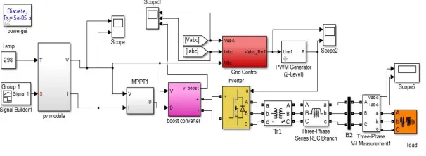
Fig 2. Circuit diagram of the proposed system.
IV. MODELLING OF GRID CONNECTED HYBRID SYSTEM
A. MODELLING OF PV MODULE
The PV system consists of photovoltaic modules, a boost converter and grid controlled inverter. The dc-dc boost converter is responsible for tracking maximum efficiency of the PV module. The output current-voltage characteristic of a PV panel is expressed by equation (1),
I=IPH -Is [exp q(V+IRs)-1] (V+IRs) (1)
NKT RSH
where I is the load current, IPH is the photocurrent , Is is the diode current , q is the electron charge, V is the terminal voltage of the cell, N is the diode ideality factor, K is the Boltzmann constant, T is the cell temperature, RS and RSH is the series and shunt resistance respectively.
B. MODELLING OF BATTERY SYSTEM
The battery system consists of grid controlled inverter and transformer. The battery system generates DC voltage of 400V which is fed to the inverter .The output of the inverter is three phase AC voltage of 400V.
V. SIMULATIONRESULTS
The proposed method is verified by using matlab simulink model.
Fig 4 Simulation of conventional grid
The output of the conventional grid is 400 V and output current of 10 A is shown in Fig 5 .
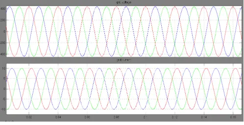
Fig 6 Simulation of battery source system
The simulation of Battery system with RL load is shown in Fig 6.The input DC voltage is 440 V. The gate pulse to inverter is through grid control method.
Fig 7 Simulation output of battery source system
The output voltage of the battery system connected to RL load is 400 V is shown in Fig 7 .The output current obtained is 2.8 A.
Fig 8 Simulation of Solar Photovoltaic system with MPPT
Fig 9 Output voltage ,current and power waveform of boost converter
The output voltage of the boost converter is 400 V is shown in Fig 9 . Here solar irradiance of 1000W/m2 500W/m2 and 800W/m2 is given to check the MPPPT.
Mode1: Without DVR
Simulation of the system is done after connecting PV and battery system to the conventional grid. In this topology DVR is not implemented
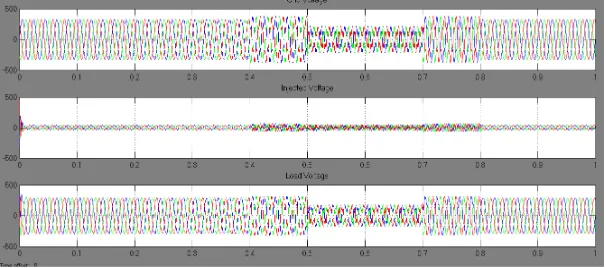
Fig 10 .Simulation of system without DVR
The output voltage of the grid connected system contains voltage fluctuations is shown in Fig 12.Here three phase fault is being created to the grid system in order to create a voltage fluctuation during time period 0.4 to 0.8 sec.
Mode1: Without DVR
Simulation of the system with sag and swell is done after connecting the designed DVR.
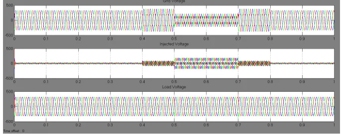
Fig 12 .Simulation of system with DVR
Fig .12 shows the simulation model of the grid connected hybrid system where power quality controller has been
implemented. Fig 13 shows the output voltage when three phase fault is being created to the grid connected system inorder to create a voltage fluctuation during time period 0.4 to 0.8 sec.
Fig 13 .Simulation output of system without DVR
VI.CONCLUSION
In this paper a power electronic based equipment DVR to improve power quality issues in microgrid like voltage sags and swell has been presented. When the DVR is in operation the voltage sag and swell is mitigated almost completely, and the RMS voltage at the sensitive load point is maintained at about 90%.The proposed method has been verified by matlab simulation results.
REFERENCES
[1] Dayi Li, Z.Q. Zhu,” A Novel Integrated Power Quality Controller for Microgrid”, IEEE Transactions on Industrial Electronics,
10.1109/TIE.2014.2362495.
[2] B. Lasseter, “Microgrids ,” IEEE Power Engineering Society Winter Meeting, Vol.1, pp. 146-149, 2001
[3] R. Majumder, A. Ghosh, G. Ledwich, and F. Zare, “Power management and power flow control in a utility connected microgrid,” IEEE Trans.
Power Syst., vol. 25, no. 2, pp. 821–834, May 2010.
[4] Anita Pakharia, Manoj Gupta ―Dynamic Voltage Restorer for Compensation of Voltage Sag and Swell: A Literature Review, International Journal of Advance in Engineering & Technology, vol 4, issue 1, july 2012, pp.347-355.
[5] P. T. Nguyen, Tapan. K. Saha, “Dynamic Voltage Restorer against Balanced and Unbalanced Voltage Sags: Modelling and Simulation,” IEEE
Power Engineering Society General Meeting, vol. 1, pp. 639-644, June 2004.
[6] M. V. Kasuni Perera, “Control of a dynamic voltage restorer to compensate single phase voltage sags” Master of Science Thesis, KTH
Electrical Engineering, Stockholm, Sweden, 2007.
[7] Himadri Ghosh, Pradip kumar Saha, ― "Design and Simulation of a Novel Self Supported Dynamic Voltage Restorer (DVR) for Power Quality Improvement," International Journal of Scientific & Engineering Research, vol. 3, issue 6, june2012, pp 1-6.
[8] Himadri Ghosh, Pradip kumar Saha, ” Design and Simulation of a Novel Self Supported Dynamic Voltage Restorer (DVR) for Power Quality
Improvement” International Journal of Scientific & Engineering Research, vol. 3, issue 6, june2012, pp 1-6.
[9] K P J Pradeep, C Chandra Mouli, "Design and Implementation of Maximum Power Point Tracking in Photovoltaic Systems," International
Journal of Engineering Science Invention, vol. 4, pp.37-43, March 2015
[10] K. H. Hussein and I. Muta, “Maximum photovoltaic power tracking: An algorithm for rapidly changing atmospheric conditions,” Proc. Inst.
Electr. Eng. Gener., Transmiss. Distrib., vol. 142, no. 1, pp. 59–64, Jan. 1995.
[11] E. Koutroulis, K. Kalaitzakis, and N. C. Voulgaris, “Development of a microcontroller-based photovoltaic maximum power point tracking
controlNsystem,” IEEE Trans. Power Electron., vol. 16, no. 1, pp. 46–54, Jan. 2001.
[12] DineshKumar. T, Subramani. M, “Design and Implementation Maximum Power Point Tracking in Photovoltaic Cells” Energy Efficient