Sensorless Direct Torque Control of
Permanent Magnet Synchronous Machine
Using Buck Boost Converter
Tarun Kumar1, Baljit Singh2
M.Tech Student, Department of Electrical Engineering, DAVIET, Jalandhar, India1
Asst. Professor, Department of Electrical Engineering, DAVIET, Jalandhar, India 2
ABSTRACTA direct control technique model is implemented with permanent magnet synchronous motor (PMSM). The above combination is represented in MATLAB/Simulink. To improve the dynamic performance combined model (DTC-PMSM) is combined with Buckbooster convertor is combined with DTC-PMSM. The various simulation results are depicted within in the finish of this paper.
KEYWORDS: DTC, Sensoreless, Buckbooster, PMSM, Torque.
I. INTRODUCTION
3. To develop hybrid model of DTC on PMSM and Buck Boost converter to investigate performance of PMSM. Next section enclosed some brief study of previous technique. The next section will outline methodology of the proposed objectives. The Simulink design and results has been furnished in last section of the paper.
II. THE MATHEMATICAL MODELS
This paper represents the three distinct models which are designed in MATLAB and Simulink. First model represents the combine model of DTC and PMSM. Second model depicts the model of the buck booster convertor. Then to improve the efficiency of the system previous two models are combined into one model i.e. DTC-PMSM with Buck Booster convertor. However, this section outlines mathematical model of PMSM and control system of PMSM are defined in next section.
a. Mathematical Model of DTC
Fig.1 Mathematical Model of Direct Control Torque Model.
The principal of DTC relies on the command of the inverter switches by applying a specific voltage sequence determining its standing. the selection of the voltage vectors is created by a switch table looking on the machine’s electromagnetic states obtained from the physical phenomenon comparators of force and flux. it's thus to keep up the force and flux inside their physical phenomenon bands.
The equation for measuring the voltage and currents are beneficial to calculate electromagnetic torque, stator flux and sectors are defined as[5]:
H
Switching Table
Invertor
Motor
Estimator
H
PI
Hysteresis
Comparators
Speed Reference, Measured Speed
TORQUE
b. Speed PI Controller
PI Controller is utilized to provide torque reference generation and speed regulation. This PI controller will compensate the integral action of the regulator. The drive takes the speed reference that's such as by the Speed Reference choice Block and compares it to the speed feedback.
The speed regulator uses proportional and integral gains to regulate the torsion reference that's sent to the motor[6]. This torsion reference tries to work the motor at the specified torsion necessary to keep up speed. This regulator also produces a high information measure response to hurry command and load changes.
c. PMSM Model
A permanent magnet synchronous machine is developed by considering following hypothesis [7]: a) Sinusoidal EMP is induced
b) The losses (eddy and hysteresis) are negligible.
c) There is no field current kinetics and winding of stator are balanced.
In reference to dq frame the equations for the torque, stator flux linkage and electromagnetic torque are as follows:
Where, Ld and Lq are inductances, ωr is rotor speed, np depicts the poles in contains, id and iq are the currents of stator with reference to dq frame; Te and Tm represents the torque of electro-magnetic developed and load torque of motor respectively [8].
III.THE PROPOSED METHODOLOGY AND SIMULINK MODELS
a. Simulink Model of BUCK BOOST CONVERTER
In this paper in spite of conventional DTC and PMSM models; the BUCKBOOST converter model is also attached.Thebuck boost convertor model is depicted in Fig 2.
Fig.2. A Simulink Model OfBuckboost Converter
Table.1. Parameter of MOSFET S.NO Parameters Symbols and Values 1 FET Resistance Ron = 0.1 ohm 2 Internal Diode Inductance Lon=0 ohm 3 Internal Diode Resistance Rd=0.0.1 ohm 4 Internal Diode Forward
Voltage
Vf=0(v)
5 Internal Current 0 (A) 6 Snubber Resistance 1e5 (ohms)
To cope with the current industry needs an precise model of system is desired which must have specifications like accurate accuracy, and reduced repose time of the system. Many methods like impedance matching, analysis of small signals, state space method e.t.c are designed by considering above parameters. Buck Boost dc-dc converter in continuous conduction model [9] is also a good method to get accurate results.
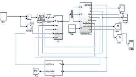
b. The Simulink model of DTC & PMSM
Fig. 3: A Simulink Model of Direct torque Control of Permanent Magnet Synchronous Motor.
Table 2. Parameters considered for the model of DTC
S.No Parameters Symbol and Value
1 STATOR RESISTANCE Rs= 11.6; [Ohm]
2 ROTOR RESISTANCE Rr= 10.4; Ohm]
3 STATOR INDUCTANCE Ls= 0.579; [H]
4 ROTOR INDUCTANCE Lr= 0.579; [H]
5 MUTUAL INDUCTANCE Lm= 0.557; [H]
6 INERTIA J= 0.002; [kgm^2]
7 No. of poles p= 2; POLES
8 FREQUENCY f= 50; [Hz]
9 POWER Pn= 750; [W]
10 SPEED Nn= 800; [o/min]
c. Proposed Combined Model of DTC-PMSM and BUCKBOOST
Fig.4. Simulink model of DTC-PMSM and Buck-Boost Convertor
The above figure depicts the combine model of DTC-PMSM model. However, Fig.5. shows the part of DTC model where the buckbooster applied befor the invertor to boost up the signal.
Fig.5. Simulink model of DTC and Buck-Boost Convertor
The proposed model will improve the output voltage and torque values. This model will yield to following characteristics:
a. Electromagnetic Torque Equation (MATLAB)
b. The coefficient is calculated as
sigma= Ls*Lr-Lm*Lm ; where Lm is Mutual Inductance of motor.
IV.RESULTS AND CONCLUSION
By considering the parameters described in above sections, the following results are obtained with the help of MATLAB and Simulink. Fig 6 represents the output of current variation with DTC-PMSM model. The value of current decrease from t= 0.0 to t = 0.58 and then the current value oscillates in dictated manner and not much stable. Fig. 7. represent the output current of DTC-PMSM model with Buck Booster converter. The current remains stable from t=0.0.1 and remain stable.
Fig.7. The variation of stator current vs time curve of DTC-PMSM &DTC-PMSM with Buckbooster Model
The total output torque of the DTC-PMSM is shown in Fig.8. and it can be observed that there is consistency in the output result but values remain oscillating and not stable. This thing is improved in our proposed model where the output of torque is start remain stable and constant at t= 0.01. Fig.8. (second) the improved values of DTC-PMSM and Buck Booster Convertor model.
V. CONCLUSION
Two totally distinct models of sensorless model are outlined in this paper. DTC evidenced to be a good assure of flux and torque and there is to alter model parameters of load values. The combined model of DTC-PMSM and Buckbooster performed better in terms of motor characteristics in comparison to DTC-PMSM model. The obtained torque curve is more consistent and précised than DTC-Model. Buckbooster integration with DTC-PMSM improve the overall characteristics of permanent magnet synchronous motor.
REFERENCES
[1]. Li Ye and Yan Xinpin, "The perspective and status of PMSM electrical serro system," Micromotors Servo Technique, Vol.4, pp. 30-33, 2001. [2]. F. M. Abdel-kader, A. El-Saadawi, A. E. Kalas, O. M Elbaksawi, "Study in direct torque control of induction motor by using space vector
modulation". Power System Conference, MEPCON 2008.l2th International Middle-East, pp.224 - 229, 2008.
[3]. Dixon, I. Nakashima, E.F. Arcos, and M. Ortuzar, “Electric vehicle using a combination of ultra capacitors and zebra battry,” IEEE Trans. Ind. Electron., vol. 57, no. 3, pp. 943-949, March 2010.
[4]. A. Davoudi, J. Jatskevich, and T. De Rybel, “Numerical state space average value modeling of PWM dc-dc converters operating in dcm and ccm,” IEEE Trans. Power Electron., vol. 21, no. 4, pp. 1003-1012, July 2006.
[5]. Vargas, R., Rodriguez, J., Ammann, U. Predictive Current Control of an Induction Machine Fed by a Matrix Converter With Reactive Power Control[J] IEEE Transactions on Industrial Electronic. 55(12):4362-4371, 2008.
[6]. H. J. Guo, Y. Shiroishi, and O. Ichinokura, “Digital PI controller for high frequency switching DC/DC converters based on FPGA,” in Proc. IEEE-IETELEC, 2003, pp. 536–541.
[7]. Yasuhiko Dote, “Servo motor and motion control using Digital Signal Processors”, Prentice Hall, Eagle Wood, Cliffs, New Jersey, 1990. [8]. M. Fu and L. Xu “Sensorless direct torque control technique for permanent magnet synchronous machine,” Ind. Apply. Conf. 34th. Annual
Meeting., vol. l, pp. 159–164. 1999.
[9]. R. Morales-Caporal and M. Pacas, “Encoderless predictive direct torque control for synchronous reluctance machines at very low and zero speed”, IEEE Trans. Industrial Electronics., vol. 55, no. 12, pp.4408-4416, 2008.
[10]. J. Zhao, “Anefficient Wide-Speed Direct Torque Control Based on Fuzzy Logic Technique,” University of Toledo, 2012.
[11]. S. Lisauskas, D. Udris, and D. Uznys, “Direct Torque Control of Induction Drive Using Fuzzy Controller,” Electron. IrElektrotechnika, vol. 19, no. 05, pp. 13–16, 2013.