I m p e d a n c e F u n c t i o n C a l c u l a t i o n s for S a t u r a t e d L a y e r e d Soils
Nick Simos 1), A. J. Philippacopoulos 1), Dimitri Papandreou 2), Norbert J. Krutzik 2) and W. Schutz 2)
1) Brookhaven National Laboratory, Upton, New York, USA 2) Siemens AG, Power Generation Group (KWU), Germany
A B S T R A C T
While extensive interest and research effort has for year been devoted to the estimation of the soil stiffness in its interaction with structural foundations, specific problems that are unique to given realistic situations prompt the re-examination of the issue with ever developing computational tools. In this study the effect of soil saturation in a layered half-space is examined with primary focus the influence of the position of the water table on the stiffness and radiation damping of the soil as it interacts with a strip surface foundation. Specifically, a two dimensional plane strain model of a soil layer overlaying a half space is the basis of the parametric analysis. The supporting theory to the computational model is Biot's two-phased theory. Prior to presenting new results, the current methodology is tested against previous analytic solutions involving two-dimensional axisymmetric descriptions of the same problem with comparative results included in this paper. At issue is the ability of the plane strain model to capture the main characteristics and amplitudes of the response of a realistic foundation and thus be used to derive conclusions in more complicated problem arrangements. Results from a series of different problems involving a half space overlayed by a surface layer and different degree of saturation in both the layer and the half space are presented. Conclusions are reached on the basis of the vertical foundation motion and the resulting impedance functions.
I N T R O D U C T I O N
The dynamic response of strip foundations interacting with saturated underlying media has drawn some attention primarily because of the role of the pore fluid on the response parameters. Typically the contribution of the pore fluid is accounted for in the form of an "equivalent" soil whose Poisson's ratio approaches p -- 0.5. It has been assessed, however, that susch simplification may hold true for a small frequency range.
In order to address the complete SSI problem that accounts for the role of pore fluid, a dynamic finite element computational scheme were adopted. The governing equations are those of wave propagation in saturated media as developed by Biot [1] of the plain strain form. The POROSLAM [7] special program which has been designed for analysis of problems involving saturated porous media was used.
Analytical solutions to the problem that can be used for comparative purposes before embarking into complicated cases are rather limited. Results either a rigid strip footing on a half space or of a circular footing on a half space overlayed by a surface layer are in [2] and [10 ] respectively.
While the above available closed form solutions are representative only of a dry underlaying soil medium, the comparison is still usefull in assessing both the impedances and the implementation of the radiating boundaries. In addition, the comparison of the plane strain results of this study with those of the axisymmetric case will provide a good undestanding as to how precise the plane strain analysis is when analyzing realistic soil structure interaction problems with foundation dimensions that are not quite of the plane strain type. It should be pointed out that the size of the computational problem can grow unfavorably as one deviates from the 2-D, plane strain problem. As a result, the gain in problem dimensionality is offset by the prohibiting cost of the matrix invertion. While excellent agreement has been made between the plane strain analytical and finite element analysis results, shown in thiis paper are comparative results between the plane strain and the axisymmetric formulations. In addition, it has been shown in [9] that the frequency dependant 2-D transmitting boundaries for dry or saturated soils and their implementation into the finite element scheme work extremely well in the plane strain formulation.
SMiRT 16, Washington DC, August 2001 Paper # 1755
F O R M U L A T I O N OF T H E M A T H E M A T I C A L / C O M P U T A T I O N A L
M O D E L
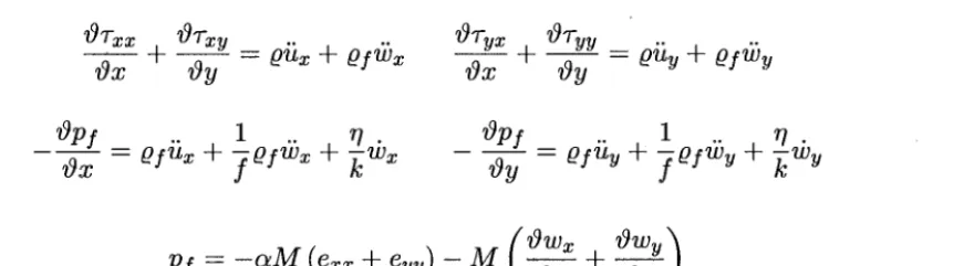
Figure 1 is a schematic of the well defined problem of a massless, rigid strip foundation resting on a surface layer overlayng a half space. Shown is the arbitrary location of the water table which may be elevated to the ground level. It is assumed t h a t the soil beneath the water table is fully saturated. A perfect bond is assumed between the foundation and the underlying soil layer.In the parametric analysis the foundation is considered to be rigid but either pervious or impervious to the pore fluid. In the pervious case the pore pressure vanishes along the entire surface and even under the foundation. In the impervious case the pore pressure can build up during the dynamic action on the foundation. Shown in Figure 1 are the radiating boundaries at the sides and b o t t o m of the finite domain that has been selected for the finite element model. The mathematical model is formulated based on Blot's classical theory of elastodynamics of porous, saturated medium. The equations of motion are expressed in terms of the soil matrix and pore fluid displacements according to the relations,
~97xx
~9T~y
0%~
OTVV _
v~ x
t v~ y = O ~ x + O f ib x
v~ x + O----Y- -- O ~ y + O f i3 y
(1)
where
Op f
1
~7
~gp f
1
~1.
= + + = + + (2)
Pf - - c ~ M (exx + eyy) - M ( ~gwx~gx + OWy)~gy
In the above relations, ui are the solid matrix displacements, wi are the pore fluid displacements,
Tij
are the total stresses, p f is the pore pressure,f
is the porosity, 0 is the total mass density, ~of is the fluid mass density, o~ is the compressibility of the solid,M
is the compressibility of the fluid, r / i s the fluid viscosity, and k is the soil permeability.The intergrannular stresses and pore pressures vanish at the free surface and outside the interface of the foun- dation and the s u b s t r a t u m except for the case of a pervious foundation that allows for the pore pressure to vanish even at the interface. For a saturated substratum and an impermeable foundation the pore fluid is allowed to move along the foundation-soil interface. In all cases the foundation is assumed massless and rigid.
In order to evaluate the impedances, the foundation was subjected to harmonic vertical, horizontal and rocking motions of unit amplitude and varying frequency. Impedances are viewed as the total resisting force exerted by the soil on the harmonically vibrating foundation and is mathematically shown below:
Fi (w) - It" Tij (W) ds
; i , j - x , y
(3)
where c is s t r u c t u r e / m e d i u m interface b o u n d a r y and 7ij -- (Tij --
a p f
is the bulk stress. In the integral above it is the bulk stress that contributes to the opposing force and thus the contribution from the pore pressure that may be present in the soil at the interface with the foundation is properly accounted for. In the next section, impedance comparisons between cases involving an impervious foundation (and thus presence of pore pressure) and a pervious one (pore pressure vanishing at the interface) are presented showing the contribution of the pore fluid to the opposing force. Impedances for vertical, horizontal and rocking motions respectively are expressed in the form,K v v - kvv -t- i(~oCvv
K h h -- khh + i~oChh
K r r - krr -ff iOLoCrr
where,
I m [Fi] w b
k i i - -
Re
[Fi] cii - - OLo - -O~o is the dimensionless frequency of the analysis that relates the frequency of foundation vibration w to the half width b and the shear velocity of the soil Vs. The real and imaginary components of the impedance were normalized further by expressing them as shown below. These normalized impedance forms appear on all the figures shown in this paper.
~ n o r m _ k i i ( - ] n o r m _ cii
l ~ i i vz~
b½
b½
To ensure that all wavelengths are properly accounted for in the harmonic analysis, the surrounding soil was dis- cretized in a way that allows the transmission of all the frequencies in the selected range of ao. The final finite element model reflected the minimum required discretization such that any further refinement would not alter the impedance calculations. It should be noted, however, that improper finite element sizes for the frequency range selected for the problem has shsown to produce results that show significant deviation from the "converged" solution.
E V A L U A T I O N
O F I M P E D A N C E
F U N C T I O N S
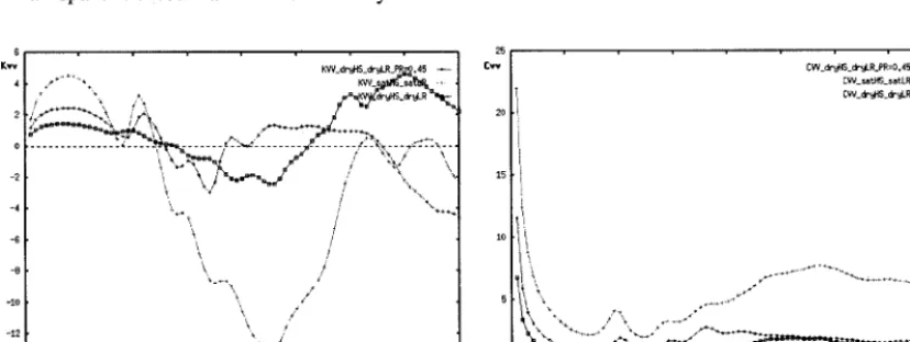
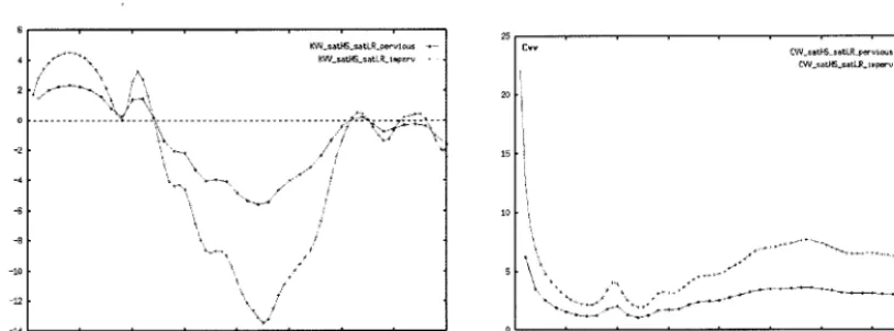
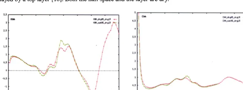
In this paper the effects of various parameters such as shear velocity, damping, water table level, foundation/soil interface, and half space/layer impedance variation are studied through the analysis of vertical foundation motions. However, to establish the validity of the the plane strain model when compared to analytical axisymmetric results, horizontal and rocking impedances have been also calculated. Figures 3 through 5 present the comparison between the present study and available axisymmetric results [10]. The agreement both in terms of impedance frequency dependance and amplitude is very good. Differences are more prominant in small dynamic frequencies due to the fact that the plane strain formulation experiences singularities at the center. Figure 6 depicts impedance functions for a half space that is either dry or saturated and overlayed by a surface layer. Of interest is the establishment of the effects the soil saturation have on the dry soil impedances. The acoustic impedance influence at the interface of the half space and the layer is shown in Figure 7 where the shear velocity ratio is varied. Interesting results are seen in Figure 8 where the saturation level is brought up to the mid-depth of the top layer. While in the low frequencies it follows, as expected, the dry soil response, the layer frequency is clearly changed by the presence of the water table. To re-examine the issue of the
equivalent
soil instead of saturated one, analyses were performed with high poisson's ratio. Figure 9 presents results that are compared to the bounding cases of dry and actual saturated soil. Figure 10 presents the effects of hysteretic damping in the soil to the vertical impedances. As expected, the effects are prominant in the higher frequencies. Lastly, in Figure 11 two types of interface conditions under the foundation are examined and compared. Specifically, impermeable and pervious foundations on saturated soil should have a profound effect to the impedances due to the fact that in the pervious case the pore pressure vanishes and it does not contribute to the opposing resultant force.C O N C L U S I V E
R E M A R K S
R E F E R E N C E S
10.
11.
12.
1. Biot, M.A, "The theory of propagation of plastic paves in a fluid-saturated porous solid, I,low frequency range, II, higher frequency range," Journal of Acoustical Society of America, 28, pp. 168-178, 179-191, 1956.
2. Luco, J.E and Westmann, R.A, "Dynamic Response of a Rigid Footing Bonded to an Elastic Half Space," Journal of Applied Mechanics, Paper No. 71-APMW-15, 1972.
3. Costantino, C.J. and Philippacopoulos, A. J., "Influence of Ground Water on Soil-Structure Interaction," NUREG/CR-4784, 1987.
4. Phillipacopoulos, A.J., "Axisymmetric Vibration of Disk Resting on Saturated Layered Half-Space," Journal of Engineering Mechanics, Vol. 115, No.10, pp. 2301-2322, 1989.
5. Pais, A. and Kausel, E., "Stochastic Response of Foundations," Department of Civil Engineering, MIT, Research Report R86-6, 1985.
6. Johnson, J.J., "Soil-Structure Interaction: Status of Current Analysis Methods and Research," NUREG/CR- 1780, 1981
7. Simos, N., Costantino, C.J. and Philippacopoulos, A.J., "POROSLAM. Two-DimensionM Dynamic Solution of Elastic Saturated Porous Media," BNL Technical Report 1996
8. Lung, R.H., "Seismic Analysis of Structures Embedded in Saturated Soils," Ph.D. Thesis, Department of Civil Engineering, City University of New York, 1980.
9. Philippacopoulos, A.J., Simos, N. and McSpadden, T., "Impedance Functions of Footings Embedded in Satu- rated Strata," Proceedings of the 27th Joint Meeting of US-JAPAN Panel on Wind and Seismic Effects, May 1995.
Costes, D. and Culambourg, C., "Equivalent Soil Resonators for Layered Half Spaces," 8th SMiRT Trans, Paper K5/2, Vol.K, pp. 159-164, 1985
Niwa~ M., Yahata, K., Ishibashi, T. and Ohta, T., "A Parametric Study of a Layered Medium Based on the Vibration Tests," 8th SMiRT Trans, Paper K7/2, Vol.K, pp, 279-286, 1985
Tohma, J., Ohtomo K., Kurimoto, K. and Arii, K., "Experimental Study on Dynamic Soil-Structure Interaction," 8th SMiRT Trans, Paper K7/3, Vol.K, pp. 287-292, 1985
' 4
N
\ \ \
\
N
% % %
Stdp Foundation
Water Table Level I
stress free surface
Surface Layer 0f_s, dens, poisson
• -- - - -- ratio, damping)
/
/ / / / / / / / / / / / / / / / [ / / / / / / / / / / / / / / / / / / /
• ~ J / , Half space (V_hs, dens, PR, damping)
~
.. Transmittingboundaries
•
\
/ / / / / / / / / / / / / / / / / /
Figure 1. Schematic representation of a strip foundation resting On a layered half-space
"~ 111\ -i
[ z i 1 -
10
; 1i~ Lu
. 0 . ? i .... ! 2j r [ A ~ [ h " " ~
0 ~ 2 3 4 5 6 7 8 9 ~.~
1o ~HH ; ' - r - ~ " ~ , , _ ~ - - - ~ . r - - - l
L_ ~ " _
t c,, r, ~T r~= :~. ~,"," "'*~- {1) Luco 0.2
(2] C.[ Approach _,"
, .! ... ! , t ... I ! L ... ±._
0 1 2 3 t, 5 6 7 8 9 a o
Figure 2. Analytical solutions of horizontal impedances for a disk foundation resting on half space over- layed by a top layer [ 10]. Both the half space and the layer are dry.
3.5 . . . .
Khh KHH_dryHB_dr~ILR
3 KHH-satHS.druL~
2.5
f
! /
?%
1.5 / " ' ~ i
... ... . . . . . .
-O.5 " ~
:1 \ /
-1.5 i i i i i i
0 t 2 3 4 5 6 7
a_o
5
I t Chh '
4.5 t~
:Ii
:II
:t!
04H.dr'gRS.dr'~LR . . . . CHH_sat HS_dr~,jLR -+-
0 1 2 3 4 5 6 7
a_o
, i , - ; . . . - . ! . . . "f .... 1
1 . 2 ~ {lJ L'.:CO
"": T::'i[~T I
...
i- " ... ]
0 6 12,,
0 i 2 3 t, 5 ~ 7 8 9 %
0.50 . . . . i ; " I ~ ' ,F "
Kc~,, " / 7 " X
0/,0~.
0,3C, ~ / ... (11 -4
,-
/ / i : I
i;-
(:I
"11)
t ucoo,~o ~:
ii S
... ~_. !(2) C,C Approach
(2)C,C :,2proa?
0 I 2 3 4 5 6 7 6 9 %
Figure 4. Analytical solutions of Rocking Impedances for a disk foundation resting on dry half space and overlayed by a top layer [10].
" ~,, . . . . : , C i ~ - , ~ ; . ~ - I 0,~ . . . . ~,~ ~ 0 . - ~ ° ~ - I
1 1/\~,KRR_.tHS_d.~LR -,- I 0.4 c,, /..,, ~ '~ c~_.~s_d,~LR .... 4
1o.
I/V',
I
o.o / / " - ~ 1
o.,
"--,,
I' J
\.,'I °''
\~/-
: ~ 1 01sl;. . . .~ . . . ~- [ - .
o . . . o.i I. ~ /
1 2 3 4 5 6 7 8 0 1 2 3 4 5 6 7 8
a..O a..O
-0.4 0
Figure 5. Plane strain analysis (strip foundation) results of Rocking Impedances for dry surface layer over a half space that is either dry or saturated.
. . . .
I:,vv KVV_satHS_drgLR -*--
'\ J
"\ +"
",. j
CVV_druoHS.dr~LR - , - - CW_satHS_dr~LR CW_satHS_satLR ~ J -
-15
0 1 2 3 4 5 6 7 8 1 2 3 4 5 6 7 8
a_o a._o
5
0 0
12 . . . 4 . . . .
Kvv KV .satHS_drgLR_Vl=2V2 -.--I
I<,,
I <w
. . . ..s_Or~L~_~,.~
--
i0 K ~I~atHS_drgLR_VI=V2 ... ~ I CW . . . . HS_dr~R_VI=V2 ...
7M
~-°~"-~:'~
~I ~~,I °°~-°~-~:'~
8
,
o
... :~_:.:; ... i:)i ~ ...i,
-2 1.5
-4
.
- 1 0 ' = 0 =
0 1 2 3 4 5 6 7 8 1 2 3 4 5 6 7 8
a _ o a _ o
Figure 7. Effects on the vertical impedance by the variation in shear velocity between a saturated half space and dry surface layer•
. . . .
Kv¥ KW_satHS_satLR -*--
K V V _ s a t H S ~ t L R -~-
KW_ ~m-
, _ . . . 2 " " ' "~.-.,.. ~',~ . . . . . = , C _ ~ _ _
\
/
-15 0
0 1 2 3 4 5 6 7 8 0
a..o
•
CW.satHS_satJ_R .-*-- CVV_satHS_par tsatLR -,--
CVV_satHS_drgLR
t 2 3 4 5 6 7 8
a._o
Figure 8. Vertical Impedance results that depict the effect of the position of saturation level. Shear velocity in half space is twice that in the surface layer.
6 ' • " ' ' ' • • I 25
v v K V V _ ~ _ d r ~ R _ ~ 4 5 "*-- I £vv CW_dr~lS_dr~R_PR=0.45 -.-- K
+ " * , KVV_s -,- CVV_satlIS_satLR + -
//."'+'"--...\ /')'~ 20
_ . . . ; 7__ _ ~ . . . ,~_~=; . . . ~ ~ . . _ . ~ : c : ~ . . l
-10 k / " *"
+ 0
-14 i i i i I i i
0 1 2 3 4 5 6 7 0 1 2 3 4 5 6 7 8
a . e
a._e
Kvv KVV_dr~IIS_~_OZ
KVV _d r ~JrlS_~i-uLR~_~ Z ....
4 KVV_dr~H}fdru~R_5~
,,~ / , + 'X "
....................... ......................
-2
0
7
•
CW_dr~HS_dryLR_0% ~ - CW_dr~HS_dr~R_2% ,
CW_dr~HS_dr~LR_5%
i 2 3 4 5 G 7 8 0 1 2 3 4 5 G 7 8
n o a_o
Figure 10. Effect of hysteretic damping on vertical impedance functions in a layered half space.
-2
-4
-B
-8
-10
-19
-14 0
6 . . . .
gVV_satHS_satLR_perv i ous -*-- 4 ,, " ' ~ ' " ~ ' ~ KW_satHS_sat LR_ t mperv , -
/ , I - - - ~ ! ~
~,,~ " ~ , , ~
" 4 . \ . . . , ~ . . . . - - : ~ ,
o . . . ~ - . . . ,.~, : ~ , ~ ; -
".. ~'-~.~_.,/'" / k
\
\ % t
% ]
CW_satHS_setLR_pervi o~s -*-- CW.satHS_satLR_ i ~peru - + -
I
0 1 2 3 4 5 6 7
a_o n o
![Figure 4. Analytical solutions of Rocking Impedances for a disk foundation resting on dry half space and overlayed by a top layer [10]](https://thumb-us.123doks.com/thumbv2/123dok_us/1502588.1183926/6.596.91.498.493.645/figure-analytical-solutions-rocking-impedances-foundation-resting-overlayed.webp)