University of Windsor University of Windsor
Scholarship at UWindsor
Scholarship at UWindsor
Electronic Theses and Dissertations Theses, Dissertations, and Major Papers
2010
Optimal power management of hybrid electric vehicles through
Optimal power management of hybrid electric vehicles through
drivetrain analysis
drivetrain analysis
Ashim Raj Das University of Windsor
Follow this and additional works at: https://scholar.uwindsor.ca/etd
Recommended Citation Recommended Citation
Das, Ashim Raj, "Optimal power management of hybrid electric vehicles through drivetrain analysis" (2010). Electronic Theses and Dissertations. 8239.
https://scholar.uwindsor.ca/etd/8239
This online database contains the full-text of PhD dissertations and Masters’ theses of University of Windsor students from 1954 forward. These documents are made available for personal study and research purposes only, in accordance with the Canadian Copyright Act and the Creative Commons license—CC BY-NC-ND (Attribution, Non-Commercial, No Derivative Works). Under this license, works must always be attributed to the copyright holder (original author), cannot be used for any commercial purposes, and may not be altered. Any other use would require the permission of the copyright holder. Students may inquire about withdrawing their dissertation and/or thesis from this database. For additional inquiries, please contact the repository administrator via email
OPTIMAL POWER MANAGEMENT OF HYBRID ELECTRIC
VEHICLES THROUGH DRIVETRAIN ANALYSIS
By
Ashim Raj Das
A Thesis
Submitted to the Faculty of Graduate Studies
through the Department of Electrical and Computer Engineering
in Partial Fulfillment of the Requirements for
the Degree of Master of Applied Science at the
University of Windsor
Windsor, Ontario, Canada
2010
1*1
Library and Archives CanadaPublished Heritage Branch
395 Wellington Street Ottawa ON K1A 0N4 Canada
Bibliotheque et Archives Canada
Direction du
Patrimoine de I'edition
395, rue Wellington OttawaONK1A0N4 Canada
Your file Votre reference ISBN: 978-0-494-62726-6 Our file Notre reference ISBN: 978-0-494-62726-6
NOTICE: AVIS:
The author has granted a
non-exclusive license allowing Library and Archives Canada to reproduce,
publish, archive, preserve, conserve, communicate to the public by
telecommunication or on the Internet, loan, distribute and sell theses
worldwide, for commercial or non-commercial purposes, in microform, paper, electronic and/or any other formats.
L'auteur a accorde une licence non exclusive permettant a la Bibliotheque et Archives Canada de reproduire, publier, archiver, sauvegarder, conserver, transmettre au public par telecommunication ou par I'lnternet, preter, distribuer et vendre des theses partout dans le monde, a des fins commerciales ou autres, sur support microforme, papier, electronique et/ou autres formats.
The author retains copyright ownership and moral rights in this thesis. Neither the thesis nor substantial extracts from it may be printed or otherwise reproduced without the author's permission.
L'auteur conserve la propriete du droit d'auteur et des droits moraux qui protege cette these. Ni la these ni des extraits substantiels de celle-ci ne doivent etre imprimes ou autrement
reproduits sans son autorisation.
In compliance with the Canadian Privacy Act some supporting forms may have been removed from this thesis.
Conformement a la loi canadienne sur la protection de la vie privee, quelques formulaires secondaires ont ete enleves de cette these.
While these forms may be included in the document page count, their removal does not represent any loss of content from the thesis.
Bien que ces formulaires aient inclus dans la pagination, il n'y aura aucun contenu manquant.
DECLARATION OF PREVIOUS PUBLICATION
This thesis includes two original papers that have been previously published and two
papers are in process of being submitted which have been used in the thesis as follows:
Thesis Chapter
Chapter 2, 4
Chapter 2, 3, 5
Chapter 2, 6
Chapter 3,7
Publication Title
Power Management of a Series-Parallel Hybrid Electric Vehicles Through Optimized
Operation of Electric Motor and Engine
Efficient Power Management Through Optimized Speed and Torque Operation of
Drivetrain Components
Distribution of Power in a Series-Parallel Drivetrain Through Variable Speed-Torque
Operation of Engine and Motor Effect of Diesel Hybridization on Vehicle
Performance for Urban (city) Driving Condition
Publication Status
Published
Published
To be submitted
To be submitted
I certify that I have obtained a written permission from the copyright owners to include the above published materials in my thesis. I certify that the above material
describes work completed during my registration as graduate student at the University of
Windsor.
I declare that, to the best of my knowledge, my thesis does not infringe upon
anyone's copyright nor violate any proprietary rights and that any ideas, techniques,
quotations, or any other material from the work of other people included in my thesis,
published or otherwise, are fully acknowledged in accordance with the standard
referencing practices. Furthermore, to extent that I have included copyrighted material
that surpasses the bounds of fair dealing within the meaning of the Canada Copyright
Act, I certify that I have obtained a written permission from the copyright owners to
include such materials in my thesis.
I declare that this is a true copy of my thesis, including any final revisions, as
approved by my thesis committee and the Graduate Studies office, and that this thesis has
ABSTRACT
The inefficient performance of gasoline-engine based vehicles along with high emissions and fuel consumption can be improved through utilization of hybrid electric
vehicles (HEVs). The multiple power and energy sources in the hybrid drivetrain can be well managed through an appropriate control strategy that supervises the power
distribution. While doing so, the control strategy needs to operate every component
optimally in addition to overseeing controlled charge-discharge of battery to obtain efficient energy usage.
In this thesis an algorithm has been developed for efficient power division among the
various components of a series-parallel (S-P) drivetrain. It has been designed to manage the power flow with the least possible losses while keeping fuel economy at an optimum
level and maintaining battery state-of-charge (SOC) in a pre-defined range. The importance of optimizing both engine and motor has been discussed. Analysis has also
been presented to show possible benefit of using diesel instead of gasoline engine for
DEDICATION
ACKNOWLEDGEMENT
I am extremely thankful and grateful to my loving family whose love, support and
sacrifice has made me what I am today. I wish to express my sincere gratitude to my advisor Dr. Narayan Kar for his assistance has been vital at every step of the way. His
valuable guidance has had an immense influence on my professional growth and without his technical expertise, reviews, and criticism it would not have been possible to shape
this thesis. I would also like to thank my committee members, Dr. Mirhassani and Dr.
Lee for their valuable suggestions and guidance in the completion of this work.
I would also like to thank my fellow colleagues at the Centre for Hybrid
Automotive Research & Green Energy for their support and encouragement during the
time I spent here. Working in their friendly and encouraging company was an unforgettable and terrific experience.
In addition I would like to thank University of Windsor for providing me the
opportunity to be a proud member of its successful graduate student fraternity. Special
TABLE OF CONTENTS
DECLARATION OF PREVIOUS PUBLICATION iii
ABSTRACT iv
DEDICATION v
ACKNOWLEDGEMENT vi
LIST OF FIGURES xi
LIST OF TABLES xiii
LIST OF APPENDICES xiv
NOMENCLATURE xv
1 BACKGROUND STUDY 1
1.1 Hybrid Electric Vehicles: A Step towards a Cleaner Future 1
1.2 Control Strategies and Algorithms for Efficient Power Distribution 3
1.3 Aim of the Research Conducted 10
1.4 Overview of Thesis 12
2 DRTVETRAIN ANALYSIS AND SYSTEM MODELLING 13
2.1 Hybrid Drivetrain Architecture 13
2.1.1 Series Architecture 13
2.1.2 Parallel Architecture 75
2.1.3 Series-Parallel Architecture 16
2.2 Comparative Study of Various Drivetrains 20
2.2.1 Benefits and Drawbacks of Series Architecture 20
2.2.2 Benefits and Drawbacks of Parallel Architecture 21
2.2.3 Series-Parallel versus other Architectures 21
2.3 Series-Parallel Modes and Corresponding Power Flow Models 21
2.3.1 Electric Mode (EM) 25
2.3.2 Series-Parallel Mode (SPM) 26
2.3.3 Engine Only Mode (OEM) 27
2.3.4 Regenerative Mode (RM) 29
3 DESIGN CONSIDERATIONS AND DEVELOPMENT PROCEDURE OF A RULE
BASED ALGORITHM 33
3.1 Vehicle Dynamics for Various Driving States 33
3.1.1 Vehicle at Rest 33
3.1.2 Acceleration 33
3.1.3 Steady-State 34
3.1.4 Deceleration 34
3.2 Use of Efficiency Maps to Obtain Conditions and Constraints 35
3.2.1 Efficiency Map Utilization 35
3.2.2 Formation of Conditions and Constraints 36
3.3 General Methodology for Design of Algorithm 38
3.3.1 Managing Power Distribution during Acceleration 38
3.3.2 Managing Power Distribution during Steady-State 39
3.3.3 Maximizing Energy Capture during Deceleration 40
3.4 Optimal Drivetrain Performance through Efficient Operation of Engine and Motor.... 41
3.4.1 Optimized Power Management for Acceleration 41
3.4.2 Optimized Power Management for Steady-State 43
3.4.3 Maximized Power Regeneration during Deceleration 45
3.5 Vehicle Specifications and Parameters 46
4 ANALYSIS OF POWER DISTRIBUTION DURING A RANDOM DRIVING
SCHEDULE 48
4.1 Initialization and Generation of Random Driving Cycle 48
4.2 Evaluation of Power Distribution at Different SOC Levels 50
4.2.1 Analysis of Power Management for Low SOC 50
4.2.2 Simulation of Power Management for High SOC 53
4.2.3 Summarization of Results 57
5 ANALYSIS OF POWER DISTRIBUTION FOR A REAL-TIME URBAN DRIVING
SCHEDULE 58
5.1 Simulation for Urban Cycle 58
5.1.1 Consideration ofFTP-72 Cycle 58
5.1.2 Examining Power Management for Urban Driving Cycle 58
5.1.4 Optimization for Steady-State 64
5.1.5 Optimization for Deceleration 64
5.2 Summarization of Results 65
6 EFFECT OF OPTIMIZATING ENGINE AND MOTOR ON THE DRTVETRAIN
PERFORMANCE 66
6.1 Effect of Engine Optimization on Drivetrain Efficiency 67
6.1.1 Optimization for Acceleration Utilizing SP-mode 67
6.1.2 Optimization for Steady-State Utilizing OE-mode 69
6.2 Effect of Motor Optimization on Drivetrain Efficiency 71
6.2.1 Optimization for Acceleration Utilizing E-mode 71
6.2.2 Optimization for Acceleration Utilizing SP-mode 72
6.2.3 Optimization for Steady-State Utilizing E-mode 73
6.2.4 Optimization for Deceleration Utilizing R-mode 74
6.3 Benefit of Optimizing Engine and Motor 76
7 IMPROVEMED DRIVETRAIN PERFORMANCE THROUGH DIESEL ENGINE
INCORPORATION 79
7.1 Why Diesel Engine Based Hybrid? 79
7.2 Modifications to Drivetrain Modes 80
7.2.1 Additional Changes to SP-mode 80
7.2.2 Additional Changes to OE-mode 81
7.3 Comparative Results Analyzing Effect of Diesel Hybrid over Gasoline Hybrid 83
7.3.1 Energy Consumption while Accounting for Efficiency. 85
7.3.2 Effect on Fuel Savings for Short and Long-term Period. 86
7.3.3 Improvement in Electric Drivetrain 86
7.3.4 Effect on C02 and NOx Emissions 88
7.3.5 Economic Benefit to the Consumer 88
7.4 Significance of Comparative Studies 90
8 CONCLUSION AND FUTURE SCOPE 91
8.1 Conclusion 91
8.2 Future Scope 92
APPENDIX A EFFICIENCY TABLES 93
APPENDIX C COPYRIGHT RELEASE 95
REFERENCES 96
LIST OF FIGURES
Fig. 1.1 Variation in battery capacity for EVs, HEVs, plug-in HEVs and conventional vehicle 1
Fig. 1.2 Effect of battery size on Fuel consumption 2 Fig. 1.3 Classification of control strategies used for power management 4
Fig. 1.4 Rule-based fuzzy advisory controller 6 Fig. 1.5 Closed-loop controller for training neural network controller 8
Fig. 2.1 Power distribution for series drivetrain architecture 14 Fig. 2.2 Power distribution for parallel drivetrain architecture 15 Fig. 2.3 Power distribution for series-parallel drivetrain architecture 17 Fig. 2.4 Speed coupling through use of planetary gear arrangement 18 Fig. 2.5 Basic control structure for a planetary gear based S-P drivetrain 19 Fig. 2.6 Various modes utilized for a series-parallel powertrain: (a) Series-parallel mode, (b) Engine only
mode, (c) Electric mode, and (d) Regenerative mode 24 Fig. 3.1 Speed-Torque characteristics with efficiency information for motor-inverter 35
Fig. 3.2 Engine efficiency map based on generalized engine map 36
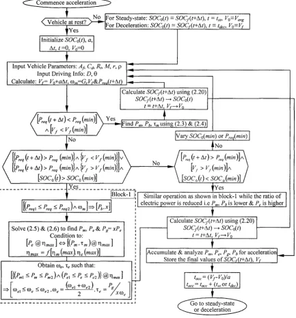
Fig. 3.3 Basic control strategy for acceleration 39 Fig. 3.4 Basic control strategy for steady-state 40 Fig. 3.5 Strategy used for regenerative braking control 40 Fig. 3.6 Control algorithm for optimal distribution during acceleration 42
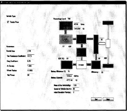
Fig. 3.7 Control algorithm for optimal power distribution during steady-state 44 Fig. 3.8 Control algorithm for maximal power capture during deceleration 45 Fig. 4.1 Initialization interface for vehicle specification and other parameters 48 Fig. 4.2 Simulation graphs for battery SOC=60% (a) Engine output power (b) Motor power (c) Battery
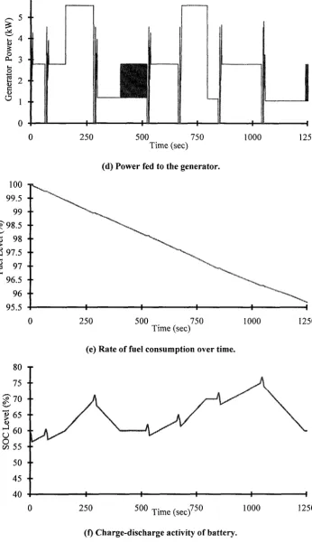
power (d) Generator input power (e) Fuel level (f) SOC level 52 Fig. 4.3 Simulation graphs for battery SOC=85% (a) Engine output power (b) Motor power (c) Battery
power (d) Generator input power (e) Fuel level (f) SOC level 56
Fig. 5.1 UDDS FTP-72 driving schedule 58 Fig. 5.2 Optimized operation of electric motor and engine for the journey 59
Fig. 5.3 Optimized operation of generator and battery for the entire journey 59
Fig. 5.4 Rate of reduction in SOC overtime for the journey 60 Fig. 5.5 Optimal utilization of components for engine-only mode (OEM) 61
Fig. 5.6 Optimal utilization of components for series-parallel mode (SPM) 62 Fig. 5.7 Optimal utilization of components for electric mode (EM) 62 Fig. 5.8 Utilization of regenerative mode when vehicle decelerates 63 Fig. 6.1 Optimal engine power output for various driving states utilizing different modes 66
Fig. 6.3 Effect of optimizing engine using SP-mode 69 Fig. 6.4 Effect of optimizing engine using OE-mode 70 Fig. 6.5 Efficient operation of motor through use of E-mode 72 Fig. 6.6 E-mode used to meet low power demand during steady-state 73
Fig. 6.7 Optimizing motor through proper component utilization 74 Fig. 6.8 Optimizing engine for different modes and driving conditions 76 Fig. 6.9 Optimizing motor for different modes and driving conditions 77 Fig. 7.1 Distribution of power for diesel/gasoline engine only operation 82 Fig. 7.2 Fuel consumed for diesel and gasoline hybrid during acceleration 84 Fig. 7.3 Fuel consumed for diesel and gasoline hybrid during steady-state 84 Fig. 7.4 Fuel consumption for 12-months for similar optimization of gasoline and diesel hybrid 85
LIST OF TABLES
TABLE 1.1 COMPARISON OF VARIOUS CONTROL STRATEGIES 9
TABLE 2.1 COMPARISON OF VARIOUS DRIVETRAIN ARCHITECTURES 22
TABLE 3.1 VEHICLE CONTROL CONDITIONS 37
TABLE 3.2 COEFFICIENTS AND EFFICIENCY INFORMATION 46
TABLE 3.3 ENERGY AND POWER SOURCES UTILIZED IN TOYOTA PRIUS 47
TABLE 4.1 POWER AND ENERGY REQUIREMENTS FOR VARIOUS DRIVING MODE 49
TABLE 4.2 IMPORTANT RESULTS FOR SOC= 60% 52
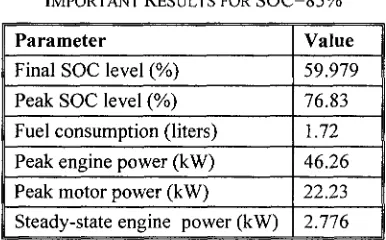
TABLE 4.3 IMPORTANT RESULTS FOR S C O 85% 56
TABLE 5.1 CHARGE-DISCHARGE BEHAVIOUR OVER THE ENTIRE CYCLE 60
TABLE 6.1 DRIVETRAIN IMPROVEMENT THROUGH USE OF SP-MODE OVER OE-MODE 68
TABLE 6.2 ADVANTAGE OF OPTIMIZING ENGINE (ACCELERATION) 68
TABLE 6.3 BENEFIT OF DIVERTING A PORTION OF ENGINE POWER TO CHARGE BATTERY 70
TABLE 6.4 ADVANTAGE OF OPTIMIZING ENGINE (STEADY-STATE) 70
TABLE 6.5 IMPROVED MOTOR PERFORMANCE ACHIEVED B Y USE OF E-MODE OVER SP-MODE 72
TABLE 6.6 OPTIMIZED VERSUS UNOPTIMIZED MOTOR USING SP-MODE (ACCEKERATION) 72
TABLE 6.7 IMPROVED MOTOR UTILIZATION 74
TABLE 6.8 BENEFIT OF MOTOR OPTIMIZATION AT HIGHER SPEED 75
TABLE 6.9 BENEFIT OF MOTOR OPTIMIZATION AT LOWER SPEED 75
TABLE 6.10 IMPROVEMENT IN VEHICLE PERFORMANCE ACHIEVED THROUGH PROPOSED CONTROL
STRATEGY 77
TABLE 7.1 FUEL CHARACTERISTICS OF DIESEL AND GASOLINE 80
TABLE 7.2 ENERGY CONSUMPTION FOR VARIOUS DRIVING STATES 85
TABLE 7.3 C 02 & NOx EMISSION COMPARISON 89
LIST OF APPENDICES
Appendix A Efficiency tables 87
Appendix B List of publications 88
The com 1m le Pb Pg Pe Pm P 1 req
P 1 ava
Ee Eb T\t Tim % T\b Vf,V0 SOCf SOCo Fuel/ Fuelo D t,At x
NOMENCLATURE
important symbols that have been utilized in this document have been listed down:
Angular speed of engine in rpm
Angular speed of generator in rpm
Angular speed of electric motor in rpm
Motor torque in Newton-meter (N-m)
Engine torque in Newton-meter (N-m)
Power output of battery in kilowatts
Input to generator in kilowatts
Engine power in kilowatts
Motor power in kilowatts
Power requirement of the vehicle in kilowatts
Mechanical power available from wheels
Energy content of fuel (gasoline or diesel) in kJ
Electrochemical energy of battery in kJ
Transmission efficiency in %
Motor efficiency in %
Generator efficiency in %
Engine efficiency in %
Efficiency of the battery in %
Final and initial speed
Average speed of the vehicle
Final State-of-charge of battery
Initial State-of-charge of battery
Final fuel tank level (gasoline)
Initial fuel tank level
Distance travelled by the vehicle
Journey duration and time step in seconds
r aero Froll Fgrad
Rt
m
8 0
c
dAf P Gr
t^acci t ace
&SS1 *SS
&dec) *dec tacci ' J I J idee
Aerodynamic drag experienced by vehicle in Newton Force for overcoming rolling resistance in Newton
Force required to overcome the gradient component in Newton
Tire resistance coefficient
Mass of vehicle in kilograms
Gravitational constant in m/s2
Angle of inclination with the horizontal in degrees
Coefficient of drag
Frontal area in m2
Air density in kg/m2
Gear ratio between the wheel and motor
Energy & power required during acceleration
Energy & power required during steady-state
Energy & power available during deceleration
Duration of vehicle accelerating, travelling at constant speed
1 B A C K G R O U N D S T U D Y
1.1 Hybrid Electric Vehicles: A Step towards a Cleaner Future
The increasing gasoline prices and fuel emissions coupled with the reducing fossil
fuel reserves necessitates an interest in the field of alternative power options. Presently,
the rate of gasoline consumption has an increasing exponential trend and recent studies
have shown that oil production is likely to peak within a foreseeable future. The ever
escalating demand for gasoline has put strain on almost every single economy in the
world, be it a developing or developed economy. In addition to that the fluctuating prices
have put the automobile corporations and consumers at the mercy of the economics of
gasoline. A feasible option for reducing the consumption and dependence on gasoline is
through application of electric vehicles (EVs) and hybrid electric vehicles (HEVs) [1].
Electric vehicle technology is an attractive option that can help reduce the dependency on
gasoline, however due to the limited range of battery and present day technological
constraints it requires more research and development to become more practical [2]. The
transition from conventional vehicle to electric vehicle is a multi-step process as the
capacity and size of the battery need to be considerably high in order to reduce fuel
consumed as demonstrated in Figs. 1.1 and 1.2 [3]-[5]. Hence there is a big void that
needs to be filled between electric vehicles and conventional vehicles; this is where
HEVs step in. As a result of battery constraints, HEVs can prove to be a viable alternative
to commercial vehicles and will be quite vital until the drawbacks of electric vehicles
have been minimized through further advancement in battery technology [1].
The biggest motivation behind the need for hybrid vehicles is the inefficiency and
high fuel consumption rate, conventional vehicles suffer from [1], [6]. The maximum
efficiency an average engine can achieve ranges from 30 to 34 % [7], [8], which is only
Gasoline 0 k\Vh
iJl-V 25 k\Vh
Conventional
(engine only)
Full Hybrid
(does not plug-in)
Plug-In Hybrid
(plug-in plus hybrid engine)
Battery Electric
(only plugs in)
0 100 200 300 400 500 600 700 800
Battery Size (kg)
Fig. 1.2 Effect of battery size on fuel consumption [4], [5].
possible for a very narrow region. This inadequacy of the engine to operate optimally
pushes the vehicle operation into inefficient operation [9]. Due to this, conventional
vehicle can offer a very limited scope of control of speed-torque of engine. The average
utilization of fuel can go up by 10-15 % through hybridization of the drivetrain which is
able to achieve better speed-torque control [10], [11]. Hence HEVs have emerged as the
technology that has provided the much needed transition from conventional to electric
vehicles especially in the past decade or so [2].
Another important reason for this transition has been the ever increasing concerns
over the greenhouse emissions and depleting gasoline reserves. The immediate solutions
to these problems are HEVs [12]. Not only do HEVs provide higher fuel economy and
fewer emissions as compared to a conventional vehicle but they have also been seen to
reduce the size of the engine which helps in reducing consumption of gasoline [13]. The
drivetrain efficiency is improved by up to 30-40% in HEVs as compared to their
counterpart conventional vehicles [8], [9].
A basic HEV drivetrain consists of at least one electric motor, a battery pack and an
engine (ICE). It combines the advantages of each of these devices while reducing the individual drawbacks of the motor and engine to a great deal [2], [14]. HEVs employ two
or more energy sources to meet the power requirement and therefore, their drivetrain is a
conventional vehicles. Hence the mechanical power required to drive the vehicle is a combination of engine power and motor power. Hybridization of the drivetrain
immediately provides the advantage of a downsized engine, two sources to meet the
energy requirements of the vehicle, reduced fuel consumption among many others [15]. The hybridization results in an increased fuel economy and lesser fuel emissions. Due to
presence of multiple energy and power sources it can get quite unmanageable to split the driver power demand. This could result in engine operating inefficiently making the
hybrid drivetrain completely redundant and also an additional negative effect could be
complete disregard for the state-of-charge (SOC) of the battery resulting in deep discharge. In addition to this there is power available during deceleration which can be
utilized to charge the battery. An efficient power management strategy can address all the issues mentioned above [16]. In the next sub-section an overview of the various control
strategies has been provided.
1.2 Control Strategies and Algorithms for Efficient Power Distribution
As the HEV powertrain structure combines the electric motor and engine either in
series or in parallel or a combination of both, the understanding of the drivetrain
architecture necessary for formulating control strategy.
Hybrid vehicles can be classified into three major categories depending upon their
power-train configuration namely: series HEV, parallel HEV and series-parallel HEV.
The control strategy needs to be designed quite differently for the three configurations as
their power distribution is different. As for the series-parallel, it has the most intricate
control strategy as its configuration is a combination of the series and the parallel
drivetrains [17], [18]. Vehicle design complexity increases significantly with hybrid
configurations especially for more complex architectures, because optimum controls and
other support systems are needed for internal combustion engine (ICE), electric motor
and other components to blend the power coming from the two sources. The increased
complexity needs to have an equally efficient control mechanism that optimizes the
working of the components in accordance with each other. The control strategy of these
systems is an important issue that determines the success of the vehicle. Thus the vital
(1) Efficient performance of drivetrain components
(2) Reduction in the total fuel consumption
(3) Reduction in the gross amount of emissions (C02+NOx+CO+...)
(4) Improving the drivability
(5) Maintenance of battery SOC
(6) Reduce the total cost function associated with the vehicle
While attaining the above mentioned objectives the control strategy has to see to it that the vehicle performance does not degrade. At any instant the control strategy should
be able to determine the power distribution between the primary energy source
(gasoline-engine) and the renewable energy storage system. The driver's power demand should be met by managing the power from different power sources. The optimal behavior of a
vehicle can be defined in terms of its reduction in fuel consumption.
Implementation of a power management system is usually done through a central
controller based on an algorithm that works on a principle of regulating the drivetrain power distribution. The multiple energy and power sources are managed through this
control algorithm. In case of hybrid vehicles, the power flow is controlled for electrical
and mechanical paths. In short, the primary function of the control algorithm is to either generate appropriate on and off decisions to engage and disengage drivetrain components
respectively or to modify their regions of operation for the best possible solution.
An accepted classification of the control strategies [19] can be seen to be subdivided into three categories as shown in Fig. 1.3. It can be observed that a control strategy can be
classified into three categories, rule-based, optimization based or neural network based,
which have been further explained in this section in detail:
Control Strategies Categories
Rule based Neural network based Optimization based
Fuzzy Deterministic Global Real-time
A. Rule based strategy: This approach manages the power management based on
their capability to solve real-time supervisory control of drivetrain power flow.
The basis for forming the rules of this approach is based on intuition, heuristics,
and human expertise. The mathematical models are created without any prior
information of previous driving cycle. It is based on the concept of load-leveling.
Through the use of this strategy actual operating point of engine is shifted to an
extremely close value of the optimal value of fuel efficiency, fuel emission and
economy rate for a certain value of the engine speed. When the result of this is
analyzed, it is observed that maximum fuel economy is achieved for a system
which is being operated at a low torque and engine speed value than the most
efficient one. So high fuel economy is achieved when there is less amount of
accelerator commands [20].
The difference in power demanded by the driver and that provided by engine
is compensated by the motor or it is used in replenishing the battery based on the
value of SOC. If the actual operating region on the efficiency map is changed then
the engine speed and the engine torque have to be changed as well. The engine
speed can be determined through the gear ratio and speed of vehicle. There are
two kinds of rule based strategies:
a. Deterministic rule based methods: These are based on heuristic approach
which involves analysis of power flow in the drivetrain, efficiency/fuel or emission maps of an engine, and human experiences. This is done using
the look-up tables, which is being utilized to divide the requested power
between the power sources.
b. Fuzzy rule based methods: The powertrain of hybrid vehicle is dependent
on multi-domain, non linear and time varying parameters due to which the
fuzzy logic based methods are suitable. Fuzzy logic is able to exploit the
decision making capability that the system has, which can be used to
realize the real time and sub-optimal power demand. Hence from the
Normalized Driver' Accelerator Pedal ]
Response
Normalized Vehicle ] Acceleration
Normalized Fuel
Vehicle Speed
Normalized Accelerator Pedal Position (App)
Fuzzy Controller
Normalized Accelerator Pedal Position
Integrator Max Offset
Advised Delta Pedal
Integrator Min Offset
Normalized Accelerator Pedal Position
If ADD >A,f
Visual Feedback •
Integrator
Controller is able to achieve : 1. Acceptable minimum acceleration
2. Minimizes fuel consumed 3. Identifies driver's intent
"Advised [Accelerator i Pedal Threshold i Position (Ath)
Fig. 1.4 Rule-based fuzzy advisory controller [22].
The main advantages of fuzzy rule based method being [19]:
1) Robust: tolerance to imprecise measurements and component
variations.
2) Adaptation: fuzzy rules can be easily varied depending upon the
needs of drivetrain.
Fuzzy based techniques [21] have proved to be of great help and have proved to provide more efficient controllers. A recently developed
fuzzy-based controller explained in [22]-[25], is shown in Fig. 1.4.
B. Optimization based strategy: This method is quite different from rule based
strategy as unlike it, this control strategy requires the complete knowledge of the
driving cycle beforehand [19]. In this, the approach is to generate optimal torque
references for various power sources and then optimal gear ratios are calculated
by minimization of a cost function which is a function representing the fuel
emissions and efficiency. The optimization based control strategies are again
a. Global optimization: This kind of optimization is usually applied for a
fixed driving schedule. This can be used to compute the reduction in fuel
consumption for the given drivetrain. In order for employing this strategy
the primary knowledge that the system needs to have is of the future
driving conditions. This control strategy is quite useful for assessment,
analysis and comparative studies with the existing control strategies [26].
Some methods of this kind of optimization in use are, game theory,
dynamic programming and genetic algorithm [27]-[29].
b. Real-time optimization: As the global optimization strategies need to have
knowledge of the entire driving schedule beforehand, they prove to be
quite unrealistic for real-time implementation. In order to counter this
problem a real time control strategy needs to be developed.
In real-time optimization, the cost function needs to be reduced for
every time step and corresponding change in SOC [30]. Hence on the
basis of equivalent fuel consumption, the global criterion is replaced by a
local one that is creation of an instantaneous cost function. This cost function is a weighted sum of the fuel consumption and equivalent fuel
consumption related to the SOC variation equivalent consumption
minimization strategy (ECMS).The equivalent fuel consumption can be
defined as extra fuel consumption that will be required to charge battery in
the near future.
C. Neural network based strategy: This is a relatively new kind of control strategy
which has found application in the automotive drivetrain control recently. This is
mainly due to its ability of being adaptive in nature that is its ability to
dynamically update itself. Through the artificial neural networks precise
non-linear modeling can be obtained which makes it an ideal option for providing
solution for controlling a non-linear system. An example of this strategy is the
recurrent neural network controller explained in [31]. This strategy employs a
closed-loop control method in order to train the neural network controller, which
SOC(t-l)
soC(t)
sAt-i)
Neural network controller
T„<7)
coe(i)
a>"M
TdM
Converter
Constraint verifier
Te(Q
coe(t)
Tg{t) cog(t)
Tm(0
a>m(t)
Neural network
model
SOC(t)
sM
Vf
60
40
. 20
0
A
H
Driving schedule
Mm
0 200 400 600 800 1000 1200 1400
Time (s)
Fig. 1.5 Closed-loop controller for training neural network controller [31].
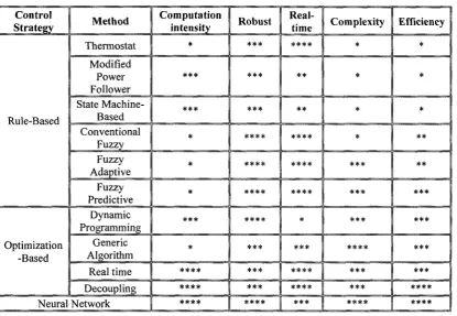
Based on the complexity, efficiency and other factors a comparison has been
provided in Table 1.1 for the various strategies discussed. Table 1.1 presents the comparative advantages and disadvantages of the various control strategies
When it comes to robustness capabilities of the system, fuzzy rule-based and
optimization based strategies are apparently superior. As for the online implementation,
fuzzy logic based and real time methods are best possible choices. Neural network
control strategy is an appropriate method for non-linear optimal control. Neural network
controller can get a better efficiency on the same vehicle than the fuzzy rule-based
optimization [32]. But due to the high computations and complexity, the neural network
poses a serious setback when comes to implementation and overall cost. Overall, the rule
based techniques have been seen to provide least complexity and computational intensity.
With the proper technique, this strategy can provide an optimal overall solution with
TABLE 1.1
COMPARISON OF VARIOUS CONTROL STRATEGIES
Control Strategy Rule-Based Optimization -Based Method Thermostat Modified Power Follower State Machine-Based Conventional Fuzzy Fuzzy Adaptive Fuzzy Predictive Dynamic Programming Generic Algorithm Real time Decoupling Neural Network Computation intensity * *** *** * * * *** * **** **** **** Robust *** #** ***
*P *P T* V
****
*P T* T* T*
1.3 Aim of the Research Conducted
HEVs have emerged to be quite beneficial in further enhancing and improving the
performance of the engine as compared to its performance in a conventional drivetrain. Through the addition of an electric path to the drivetrain, not only the overall efficiency
increases but also considerable reduction in the fuel consumption is achieved. But with increasing hybridization, complexity of powertrain also goes up; the inescapable
consequence of this is the need for efficient control over power distribution and various
components. This is where research needs to be conducted in order to design a control strategy which provides an optimal solution that takes into account factors like: cost,
complexity, fuel emissions, robustness etc.
The focus of research work conducted and presented in this thesis would be dealing with the design of a control algorithm for managing the power flow while keeping the
fuel consumption low, reduce emissions and cost. The objectives are achieved by following the procedure defined below:
• Utilization of various drivetrain configurations
• Obtain the speed and torque constraints for optimal performance
• Develop a control strategy to optimally operate motor and engine
• Optimal operation of drivetrain components
• Manage battery charge/discharge to maintain SOC over a certain limit
The novelty of the strategy demonstrated in this thesis, stems from the mariner in
which an optimal solution is obtained for managing power flow through the drivetrain. In
the various literatures reviewed, few [8], [9], [12] have shown to either employ or further
explain the various possible modes. But further enhancement can be achieved in these
modes through there mathematical modeling. These models would be able to represent
the power and energy relationship for the various components for different drivetrain
paths and driving conditions. Through application of drivetrain models, the control
algorithm would be able to improvise upon the existing techniques. This is mainly due to
considerations of higher number of control variables which have a dynamic relationship
consideration of efficiency maps for speed-torque characteristics. Although efficiency
maps have been seen to be employed in research work carried out earlier [1], [9] but through utilization of both the engine and motor characteristics at the 'same instant'
makes it unique. Through power solution obtained at every time step for a correlated efficiency based selection of speed and torque of engine and motor will be capable of
yielding power output for maximized and appropriate utilization of various components.
In addition to the above the battery charge-discharge characteristics are regulated based on the battery's state of charge. This is done as research carried out until now has not
1.4 Overview of Thesis
This thesis has been organized into the following chapters:
Chapter 2: This chapter talks about the various kinds of architectures that are available
for hybrid vehicles. These are then compared and importance of drivetrain
architecture to the power management has been explained. Next the power model for the various configurations considered have been developed which
is followed by models required to analyze energy and power sources.
Chapter 3: This chapter shows the steps involved in the development of a rule based
algorithm for managing power distribution of a series-parallel drivetrain. The
optimization procedure has been explained and analyzed in detail. In addition power and energy demands of the vehicle based on various parameters and
specifications that are vital to achieve control has also been discussed
Chapter 4: In this chapter the power management for a random journey has been
discussed. The analysis is presented for low and high SOC conditions in
order to understand effectiveness of algorithm in managing power
distribution and its ability to control charge-discharge pattern of battery.
Chapter 5: The focus of this chapter is to demonstrate the application of the algorithm
for an urban driving schedule. The optimization achieved for various driving
states while applying appropriate drivetrain has also been enumerated.
Chapter 6: This chapter primarily presents an in-depth analysis of effect of optimizing
the power sources while a study is conducted to evaluate the drivetrain
performance for different factors.
Chapter 7: This chapter presents the scope of improvement that can be achieved in the
drivetrain performance through incorporation of a diesel engine.
Chapter 8: The research findings of this detailed analysis have been presented in this
section. The implications of this research have been discussed and the scope
2 D R I V E T R A I N A N A L Y S I S A N D S Y S T E M M O D E L L I N G
2.1 Hybrid Drivetrain Architecture
There have been various kinds of drivetrain architectures proposed but out of these
the ones that are usually demonstrated in literature and that are being implemented to manage different components for hybrid vehicles are: series, parallel and series-parallel
[14], [33]-[37]. These architectures are based on the arrangement of various power and energy sources in different manner in the drivetrain through application of clutches and
gears. The objective of these architectures are to provide electrical and mechanical
connection among the various components which helps in managing routes for energy flow while achieving appropriate control of the system.
As the number of components go up, the complexity of the drivetrain also increases
proportionally if not exponentially. Even though series-parallel has a more complex architecture as compared to series or parallel drivetrains, this drivetrain has the capability
to combine the benefits of both these hybrid drivetrains. In a latter section, a brief
comparative analysis would be presented to highlights its advantage. In the series parallel drivetrain, the power demanded can be satisfied by either the engine, the battery-motor
combination or, by both engine and battery-motor combination usually for high power demands. The three main architectures discussed above have been explained in the
forthcoming section with diagrammatic representation of the drivetrain.
2.1.1 Series Architecture
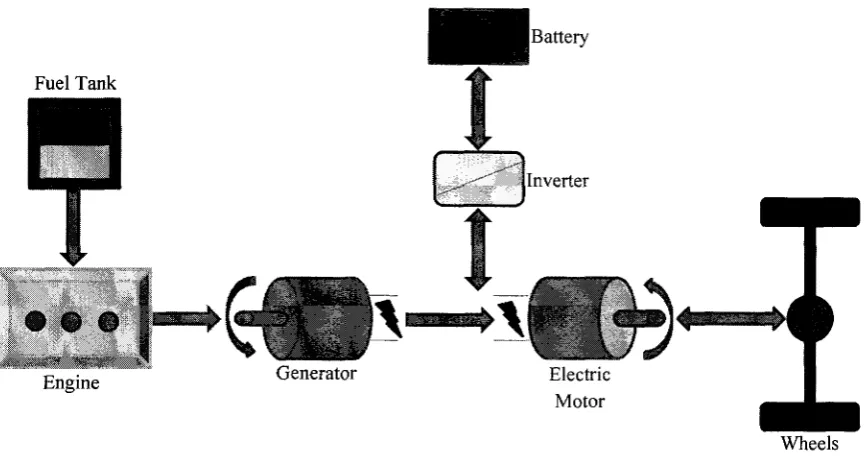
In the case of a series hybrid drivetrain, a single power source (motor) is responsible
for propelling the vehicle. This power source can be fed through two power paths as
shown in Fig. 2.1. The energy requirements of these power paths can be met through
either a unidirectional energy source (gasoline) using the ICE as a power converter
coupled to a generator or the bi-directional electrochemical energy source connected
through the means of a power electronics converter [17]. The electric motor acting as the
power source can be operated in backward motion for operating as a generator in order to
recharge the battery. Also the ICE has been observed to act as a prime mover to drive an
Fuel Tank
o © © g
Engine Electric
Motor
Wheels
Fig. 2.1 Power distribution for series drivetrain architecture.
The benefit achieved from the series drivetrain is its simplicity which enables
flexibility in the design and implementation of control strategy. But due to requirement of
three power sources (ICE, generator and motor) the efficiency of the vehicle significantly
reduces. In addition if the proportion of brake energy that can be absorbed by the
batteries needs to be increased, an unwanted consequence is that the battery and ICE have
to be sized bigger (this is due to low scope of power acceptance).
The transmission for series hybrid configuration is all electrical, via DC link. It
normally requires a power converter for each element of the system in order to control
the power flow in the form of direct current (DC) from element to element. The biggest
advantage of this configuration is the bi-directional power flow between the vehicle drive
motor and the energy storage this enhances the capability of regenerative braking.
There are quite a few modes in which the series drivetrain is known to operate based
upon the driver's need and other factor. The possible modes of operation for this
drivetrain have been listed below:
1) Battery alone mode: In this mode the engine is disengaged from the drivetrain.
2) Engine alone mode: In this mode the battery neither charges nor discharges. Only the energy of fuel is employed by the use of ICE-generator and motor.
3) Combined mode: Both the ICE-generator and battery provide power to motor which propels the vehicle using dual energy sources.
4) Power split mode: The ICE-generator power is divided into two parts, major
portion used to run the vehicle while the rest charges the battery.
5) Regenerative braking mode: The mechanical energy of wheels used to charge the
battery through motor working in generating mode.
2.1.2 Parallel Architecture
The parallel drivetrain is quite different in concept from the series one. In this
drivetrain, the power is supplied by the engine mechanically to the wheels, the same as a
conventional vehicle. Also the motor is observed to assist the engine and is also
mechanically coupled to the transmission. The parallel drivetrain is shown in Fig. 2.2.
The ICE and motor are mechanically connected to the driveshaft through two different
clutches [17]. Due to mechanical coupling of the power sources they can be coupled in
various ways speed, torque or speed-torque coupling [8]. The motor output is
considerably lower for this drivetrain as compared to series drivetrain, the reason being
that the engine provides the major portion of the power demanded from the vehicle.
Wheels
Battery ' " Electric Motor Inverter
Hence propulsion power can be met through engine only, motor energized through
the battery or a combination of both in parallel as the name of the drivetrain indicates.
The motor which can also act as a generator depending upon situation is quite vital
addition to this drivetrain as it has the functions discussed below [18]:
1) To start the engine
2) In order to supplement the engine output when vehicle is accelerating.
3) Utilize the brake energy during deceleration through regenerative braking.
4) Recharge the battery
5) To supply vehicle auxiliaries
The biggest advantage of having a motor/generator is to start the engine, which not
only removes the need for a conventional starter motor but also enables rapid, quiet and smooth restarting. Thus it is able to disengage the engine when it is not required for
propelling the vehicle. The possible modes of operation for parallel hybrids while
employing speed coupling are as follows [8]:
1) Hybrid traction: Both the engine and motor run at positive speed and torque to
provide power to the wheels.
2) Engine alone traction: The engine meets the power demand while the motor is
mechanically disengaged from the wheels.
3) Motor alone traction: The motor meets the power demand of the vehicle while
engine is disengaged from the drivetrain.
4) Regenerative braking: The electric motor is controlled to operate as a generator
that is providing negative torque which can be employed to charge battery.
5) Engine charging battery: The energy of fuel is used to charge battery. The electric
motor provides negative torque.
2.1.3 Series-Parallel Architecture
The arrangement of the series-parallel is a combination of the series and parallel
drivetrains. This makes the configuration relatively more complicated which results in the control strategy being more complex but as the drivetrain is a combination of series and
parallel drivetrains it is able to extract the benefits of both these architectures [38]-[40].
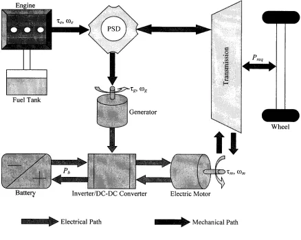
Through observation of the drivetrain in Fig. 2.3 the only major drawback of series
Fig. 2.3 Power distribution for series-parallel drivetrain architecture.
power split device for splitting the engine power; this component is responsible for
allocation of engine power to the wheels using a driveshaft and the generator. The
electricity produced by generator can be either used to charge the battery or to run the
motor. This is mainly dependent upon the SOC of battery and driver's power demand.
The motor has the capability to deliver power in parallel with the engine to the wheels. A
converter/inverter is utilized to either make the output voltage of the generator suitable
for charging the battery (AC to DC conversion) or to appropriately condition the output
power to produce electricity in order to run the motor. The engine speed can be operated
at its optimal value by controlling the speed of the generator and motor.
In case of the series-parallel hybrid, the power split device plays a vital role in the
power division procedure, for this purpose a planetary gear unit is employed which acts
Fig. 2.4 Speed coupling through use of planetary gear arrangement.
coupling between the three power sources namely the engine, motor and generator [8].
Speed coupling is employed in Toyota Prius [41] and due to its specifications and
parameters is being considered for the research work demonstrated in this thesis.
Therefore speed coupling has been further explained in brief.
In case of speed coupling two or more power sources are coupled together using a
planetary gear; this is done via coupling of their angular speeds [40], [42]. A planetary
gear as the one shown in Fig. 2.4 is employed in order to split the engine output. The
engine has a direct connection to planetary carrier through pinion gears, while the
generator and motor are connected to the sun gear and ring gear respectively. Due to
speed coupling the various gears would have the same speed value corresponding to the
component they are connected with. Depending upon the number of gear teeth certain
gear ratios are obtained which provide a relationship between the speeds of the various
power sources which is defined as follows:
cog=(De(l + C?)-o)mG (2.1)
G = ZJZS (2.2)
Where, G: Gear ratio of the planetary gear
Driver Inputs
1
Vehicle System Controller
Engine/Control
0 0 0
Transmission Control Module
High-Voltage Battery &
Control Module
Brake System Module
Fig. 2.5 Basic control structure for a planetary gear based S-P drivetrain [39].
Hence power split device employing planetary gear provides the opportunity for the
engine to operate at or near its optimal operating speed, irrespective of speed of vehicle,
while still being able to efficiently deliver power to the wheels and at the same time drive
the generator. The general control technique for a power split drivetrain has been further
explained in [25], [39] based on which a representation of the system is obtained which is
shown in Fig. 2.5. Similar to the other architecture there are some modes in which the
series-parallel drivetrain operates [35], [43]. Based on the driving characteristics various
kinds of modes possible have been enumerated below:
1) For vehicle accelerating initially and mid-range speeds driving, as the engine has
been observed to operate inefficiently, the traction power is met through the
motor alone using energy of the battery.
2) For standard driving conditions, drivetrain efficiency is kept at optimal level by
keeping major portion of the engine output to drive the vehicle while using the
3) In a high speed acceleration scenario, the generator supplements the electrical
energy provided by battery in order for the motor to generate sufficient mechanical energy.
4) During vehicle decelerating or braking, the motor would act as a generator in
order to recover kinetic energy of the wheels in order to charge the battery.
5) When the battery SOC is low or when enough electricity can be produced by
generator then a portion of engine power used to charge battery
The various modes that have been utilized for achieving optimization of the series-parallel drivetrain have been explained and discussed properly later sub-sections of this
chapter. Also power models obtained for these modes have been presented.
2.2 Comparative Study of Various Drivetrains
The most commonly used drivetrain architectures for hybrid vehicles are the series
and parallel drivetrain, another architecture that has been found to be quite beneficial is
the series-parallel drivetrain. As the series-parallel drivetrain combines the advantages of
series and parallel architectures it is quite important to understand the inherent benefits
and drawbacks of these systems.
2.2.1 Benefits and Drawbacks of Series Architecture
The main advantages of using series configuration can be summarized as:
S Engine is almost always running at its optimal speed and torque values.
S Engine and generator are sized to meet the average propulsion power requirements
S Mechanical separation of engine and generator from the wheels results in ability of running the engine at its maximum efficiency.
•f Simplicity of drivetrain means reduced control strategy complexity The drawbacks inherent to this architecture have been listed down below:
X Multiple energy conversions are required that is mechanical to electrical (using
generator) and electrical to mechanical (using motor).
X It has two electric traction devices.
2.2.2 Benefits and Drawbacks of Parallel Architecture
The major benefits of utilizing parallel configuration can be given as:
•S Requirement of only one electric machine in the drivetrain.
•S The peak power requirement for electric motor is significantly reduced as compared to a series hybrid.
•/ The engine power can be delivered to the wheels directly hence no energy conversion losses.
S The motor, engine or both can be used to meet the power demand. The drawbacks of the system are as follows:
X The mechanical coupling of the engine and motor to the wheels places a
restriction on the level of speed-torque optimization of the engine.
X An extra mechanical link is required.
2.2.3 Series-Parallel versus other Architectures
As the series-parallel configuration is developed as a combination of the series and
parallel drivetrain architectures, it is able to take advantage of both these drivetrains with
minimal drawback [44]. A feature common to series and this drivetrain is the requirement
of two electric machines. However unlike series both machines are not required to be
sized for large power requirement, which results in one electric machine, generator, to be
sized considerably smaller. The utilization of more components does lead to complexity
but through implementation of the appropriate control algorithm the overall level of
improvement can outweigh the complexity of the system. The comparison based on
various literature studies for all the 3 drivetrain architecture has been shown in Table 2.1.
2.3 Series-Parallel M o d e s and Corresponding P o w e r Flow Models
In a series parallel hybrid system there are various modes in which the drivetrain can
be configured [34]. Drivetrain configuration plays a pivotal role in how efficiently the
power is distributed among the various components. It is through apposite arrangement of
the drivetrain components that the best possible utilization of power and energy sources
can be obtained. But in order to obtain efficient operation out of the energy/power
TABLE 2.1
COMPARISON OF VARIOUS DRIVETRAIN ARCHITECTURES
Type of Drivetrain
Series
Parallel
Series-parallel
Fuel economy Improvement
Energy gained by Regenerative
braking
***
**
***
High efficiency operation control
**
*
***
Total efficiency
**
**
***
Driving performance
Acceleration
*
**
**
Continuous High output
*
*
**
should be chosen to obtain high fuel efficiency and efficient energy distribution among
the energy sources. For this purpose certain modes of operation have been selected and
some mathematical power flow models have been obtained. The concept of these models
can be understood from [12], [37]. Depending upon the vehicle requirements the mode
selection and power flow changes. Through the reconfiguration of the drivetrain optimal
operation of the components can be attained based upon the driver's power demand [12].
Based on the driving state, power requirement, SOC and other important parameters,
the drivetrain can be modeled for optimal performance based on the situation. Although
there are various possible arrangements [43], [45], only the types that have been utilized
have been explained. There are four modes that are primarily used to achieve optimal performance out of the drivetrain. Out of these modes only two of these modes have the
engine actively engaged in the drivetrain in order to power the vehicle. Fig. 2.6 shows a
physical representation of drivetrain components being engaged in order to manage power
Engine
Battery Inverter/DC-DC Electric Motor Converter
Electrical Path ••••••ll^ Mechanical Path
(a) AH drivetrain components are actively engaged.
Engine
Battery Inverter/DC-DC Electric Motor Converter
Electrical Path — • Mechanical Path
Battery Inverter/DC-DC Converter
Electric Motor
§
I
Electrical Path ^ H ^ > Mechanical Path
(c) AH electric drivetrain, only motor powers vehicle.
Wheel
Route-1
^ J & ^ V ®>g
a
.2
'55
1
£
Battery Inverter/DC-DC
Converter
Electric Motor
Route-2
Electrical Path • ^ • • ^ Mechanical Path
(d) Generator utilized for route-1 and motor used for route-2.
2.3.1 Electric Mode (EM)
This is the most preferable configuration with zero emissions, since the vehicle runs
as a purely electric vehicle. The electrochemical energy of the rechargeable battery is
utilized to power the electric motor which drives the vehicle. In this mode the engine,
generator and power split device are disabled from the drivetrain. Since the engine is not
utilized it is therefore an all electric drivetrain and has been shown in Fig. 2.6 (c).
The utilization of this mode is primarily for low to mid speed driving conditions. It is
commonly the first choice drivetrain configuration for low to mid speed acceleration. Also
based upon factors like the SOC, the distance travelled and elevation, it can also be used
for mid-speed steady state vehicle driving. Therefore it can be employed during
steady-state driving for a speed of up to 40 km/hr. These constraints have to be considered so as
to avoid deep discharge of the battery in order to keep it above a certain SOC. Due to
direct relation between the vehicle and motor speed, the motor is seen to operate at lower
speed. As power required at low speed is less than that at a higher speed, the motor
operates at a lower torque and speed which makes it operate at lower efficiency, typically
70-80 %. Even though this is true the utilization of electric mode offers much higher
drivetrain efficiency as compared to any other mode due to the fact it disables the engine.
The engine is known to be least efficient at lower speed and torque range. Hence rendering
engine inoperative would result in saving fuel as well as evading inefficient engine
operation. Through mathematical modeling the dynamics of this mode can be explained.
These equations also help in understanding the power flow in the drivetrain. The battery
and motor power can be represented through the following:
P
Pb = _J!L. (2.3)
Pm =rimPb; (where Pm = comxm) (2.4)
The electric power provided by battery has to be converted to mechanical power which is done by the use of an electric motor. Electric motor is designed for frequent stop
and start driving conditions [46]. In short the primary objective achieved through EM is
operating the vehicle at low speed steady-state conditions and for low acceleration
demands. Through this configuration high drivetrain efficiency can be achieved for city
2.3.2 Series-Parallel Mode (SPM)
This mode utilizes the energy from gasoline and battery to meet power demand. The
drivetrain does not have to be reconfigured in this mode as can be observed by looking at
the representation provided in Fig. 2.6(a). All the components are operational during the
entire operation of the mode. Since none of the components have to be disengaged from
the drivetrain, the power distribution algorithm has an immense amount of work due to
presence of multiple energy and power sources. The engine and motor speed-torque range
needs to be varied in order to obtain optimal performance.
As the name of the mode suggests, the power distribution is a combination of both
the series and parallel paths. The parallel path consists of the engine and the electric
motor providing power to the wheels in parallel. Also the series path comes into play
when a small portion of the engine power is routed through the generator to provide
power for the electric motor.
This mode is used to meet power needs of the vehicle mainly for acceleration and
sometimes during steady-state. As the battery by itself is not able to meet the power
demand during speeds over 50 km/hr, the proportion of electric to engine power is kept as
high as possible while keeping SOC in consideration. Based upon the electric proportion
this mode can be sub-divided in two parts:
• High electric ratio: When the battery is in a higher SOC range of 60 to
85%. Due to the availability of battery energy, the electric power, from the
battery powered motor, is higher and therefore less engine power is
required. As a result the proportion of electric power is higher.
• Low electric ratio: When the battery is in a lower SOC range of 30 to 60%.
Due to a lack of available battery energy, the electric power (battery
powered motor) is lower and more engine power is utilized to meet power
demands. As a result, the proportion of electric power goes down.
The operation of the EM and SPM modes are similar, except that the speed and torque
range that the motor, engine and generator operate are different. There are two main
factors that influence the operation of this mode:
• Selection of the appropriate speed-torque range of the motor and engine
• Varying the recirculation factor, x in order to control the generator output power and angular speed.
The recirculation factor is a variable that specifies how the engine power is split into
two paths: the mechanical path that is directly connected to the wheels and the electrical path through the motor-generator. Through varying the power that passes through the
electrical path the efficiency of not only engine but also the motor can be increased. The recirculation factor and the battery output can be varied in order to enhance performance
of the power sources while keeping the power lost through recirculation as low as
possible. Initially the speed-torque range of motor and engine are selected based upon the information fed from the look up tables created using efficiency maps. After this in order
to maximize drivetrain optimization, through control of the amount of engine power going through the electrical path the motor's region of operation is managed. This is done while
keeping the power through this path as low as possible. These operations are better
understood by looking at the representative model of power flow for this mode:
Pm=A^S^Pe)+^\mPb (2-5)
Pn9=r\,(l-x)P.+r\lPm (2-6)
Pe=T],Preq+Pg (2-7)
Pg={l- x)Pe (2.8)
The primary aim of utilization of SPM is to distribute the energy between the primary
energy source (gasoline) and the battery in an optimized manner such that both the engine
and the motor operate in a region of high efficiency.
2.3.3 Engine Only Mode (OEM)
The requirement of this mode is quite vital for two chief reasons: to utilize the engine
power efficiently so that the fuel consumption and emissions are as low as possible and
secondly to charge the battery whenever the SOC is below pre-defined limit. Based upon
the application of engine power to drive vehicle or to drive vehicle and charge battery
either battery or motor is disengaged from the drivetrain respectively. Through utilization
of this mode engine can be operated in higher efficiency points (r|e>25%).
This mode comes into action when the vehicle is in steady-state. The power
requirement is quite low, the modes discussed earlier are preferred over this mode. When
the speed is over 50 km/hr and either the SOC is too low or there is reason for utilizing a
small portion of engine power to charge the battery, this mode proves quite effective.
While a major portion of the engine power is used to meet the power requirement, a small
portion (10 to 30%) is routed through the generator to generate electricity which can either
be used to charge the battery when the SOC level is low or to run the vehicle when SOC is
in a certain range. On the basis of the utilization of the engine this mode can be classified
into the following:
• Drive the vehicle only: Medium to high power demand, higher speed (>50
km/hr) and medium SOC range (50 to 70%). The vehicle power
distribution can be explained from the power model developed:
Png=Ml-x) + Wmngx)Pe (2-9)
Pm = *<\gr\mpe; (w h e r e pe = ©eO (2-10)
The power passing through the electrical path is kept at a minimum level to reduce
the conversion losses while operating engine at high efficiency.
• Drive vehicle and charge battery: Medium power demand, medium speed range (40-60 km/hr) and low SOC (<50%). Power management for this
mode can be represented mathematically as follows:
^ = T i , ( i - * k *e (2-n)
Pb=XT]gG)eXe (2.12)
The output of the motor in this scenario is zero. The battery is charged in a constant
power manner. Both kinds of implementation of the mode can be seen in Fig. 2.6(b).
In order to have absolute optimization there are other factors that have been
considered. The distance traversed by the vehicle, the elevation and amount of driving
time spent during steady-state other control parameters. Based upon the driving schedule
information, all these parameters can play a pivotal role in deciding how this mode is
utilized. A portion of the engine power can be used to run the generator whose output can
be utilized to charge the battery which has been represented by (2.12). Hence this mode is
![Fig. 2.5 Basic control structure for a planetary gear based S-P drivetrain [39].](https://thumb-us.123doks.com/thumbv2/123dok_us/1500298.1183678/36.608.115.535.73.346/fig-basic-control-structure-planetary-gear-based-drivetrain.webp)
![Fig. 3.2 Engine efficiency map based on generalized engine map [7], [8], [41].](https://thumb-us.123doks.com/thumbv2/123dok_us/1500298.1183678/53.620.172.471.90.344/fig-engine-efficiency-map-based-generalized-engine-map.webp)