SMS BASED WIRELESS NOTICE BOARD DISPLAY
USING GSM MOBILE
Payal Mishra
1, Pinki Singh
2, Shivani Gupta
31,2,3
UG, Department of Electronics and Communication Engineering,
Raj Kumar Goel Institute of Technology for Women, Ghaziabad (India)
ABSTRACT
The global system for mobile communication was initially developed in the European Telecommunication Standard
Institute, which depicts protocol for second generation of digital cellular communication system that has gradually
worldwide gain and market share. It has become the de facto for global mobile communication system with more
than 80% market share. GSM standard system has developed a replacement for first generation analog cellular
networks and described digital, circuit-switched network optimized for full duplex voice telephony. The architecture
and advanced services of GSM have made it a model for third generation digital cellular system. In today’s scenario
GSM network is widely used for calling or SMS. Sometimes the places like in college, railway stations, share
market needs urgent notices which should be in real time. There is a need of real time notice display. This paper is
about to explain a GSM based electronic notice display system which we can be used to replace current
programmable electronic display. It is about to write the message in the mobile and send it as SMS to other side of
electronic notice board.
Keywords: GSM, LCD, Microcontroller, IC MAX 232 , Power Supply.
I. INTRODUCTION
In the arena of mobile technology tremendous changes are taking place and the worldwide push towards third
generation is currently at the leading edge of these transformation. In 1982 the development of GSM started with
the formation of study group Groupe Special Mobile which was established in the conference of European Posts
And Telegraphs. At present sending messages via mobile phone has become very efficient and popular. If we use
GSM mobile for displaying SMS on LCD notice board through wireless communication then, we can use the SMS
to control devices and displaying data. Globally, by using GSM networks it is possible to decode the received SMS
on mobile phone . GSM system operates at different frequency bands for 2G GSM networks operates in 900MHz or
1800MHz bands while most 3G networks operate in 2100MHz frequency band. This paper focuses advancing a
system which will display the received SMS by mobile phone on LCD notice board. The system is basically
consisting of two sections in which one is transmitting section and the other is receiving section. In transmitting
MAX232, power supply, cable and LCD display. This paper proposes different applications which will utilize
distinct advantages of GSM technology. The industrial applications of GSM are in digital transmission, nationwide
coverage, future proof compatibility, mobile system. It is a system which is designed to be error free and financially
cheap with respect to the growing technology.
II. BLOCK DIAGRAM
The block diagram of SMS based wireless notice board display using GSM mobile based on different components.
Fig.1 general block diagram for SMS display on LCD
2.1 Microcontroller
Microcontroller is a chip which includes MP, memory and input output on the same chip. It is fabricated by using
VVLSI Technology. Microcontroller is the complete computer on the single chip.
Fig.2 pin diagram of microcontroller 8051
It is the basic part of the system. It is used for interfacing the memory, display and other peripherals with GSM
memory to be reprogrammed in-system or by a nonvolatile memory programmer. When we combine a versatile
8-bit CPU with on a monolithic chip Atmel AT89C51 is the powerful microcomputer which provides a highly-flexible
and cost-effective solution to many embedded control application. This is the reason that it is used worldwide.
2.2 LCD
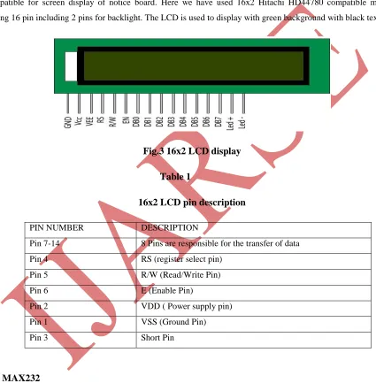
One of the most common devices attached with microcontroller 8051 is an LCD (Liquid Crystal Display). It is
compatible for screen display of notice board. Here we have used 16x2 Hitachi HD44780 compatible module,
having 16 pin including 2 pins for backlight. The LCD is used to display with green background with black text.
Fig.3 16x2 LCD display
Table 1
16x2 LCD pin description
PIN NUMBER DESCRIPTION
Pin 7-14 8 Pins are responsible for the transfer of data
Pin 4 RS (register select pin)
Pin 5 R/W (Read/Write Pin)
Pin 6 E (Enable Pin)
Pin 2 VDD ( Power supply pin)
Pin 1 VSS (Ground Pin)
Pin 3 Short Pin
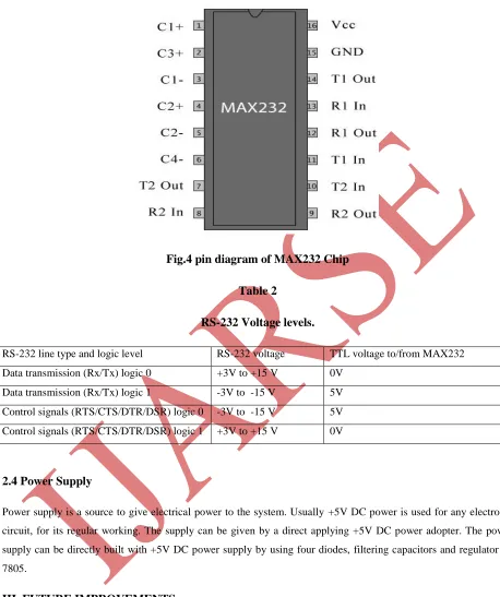
2.3 MAX232
The MAX232 is a dual driver or receiver which includes capacitive voltage generator to supply EIA-232 voltage
levels, single supply and converts the input to TTL/CMOS levels. It is compatible to operate at higher baud rates.
The microcontroller is interfaced with the PC through MAX232 level converters. It is efficient for the conversion of
Fig.4 pin diagram of MAX232 Chip
Table 2
RS-232 Voltage levels.
RS-232 line type and logic level RS-232 voltage TTL voltage to/from MAX232
Data transmission (Rx/Tx) logic 0 +3V to +15 V 0V
Data transmission (Rx/Tx) logic 1 -3V to -15 V 5V
Control signals (RTS/CTS/DTR/DSR) logic 0 -3V to -15 V 5V
Control signals (RTS/CTS/DTR/DSR) logic 1 +3V to +15 V 0V
2.4 Power Supply
Power supply is a source to give electrical power to the system. Usually +5V DC power is used for any electronic
circuit, for its regular working. The supply can be given by a direct applying +5V DC power adopter. The power
supply can be directly built with +5V DC power supply by using four diodes, filtering capacitors and regulator IC
7805.
III. FUTURE IMPROVEMENTS
The very effective and substantial improvement will be to adapt multiple receiver GSM modems at distinct position
in the geographical area which carries duplicate SIM card. Another variation can be added is multilingual display for
replace with large LED boards. The commercial model should be able to display more than one message at the same
time. Robotics technology can be controlled in a similar fashion by sending the commands to the robots.
IV. CONCLUSION
The prototype of GSM based modem has been designed efficiently. This prototype facilitates to be integrated for
notice board display which is makes it effectively mobile. The system accepts the message, stores it, validates and
displays it on the LCD board. It consists of a remote notice board connected with the modem. It is based on wireless
and error free system. The data in the system will be lost only in the power failure condition. The system provides
distinct application in the field of Railway stations, Advertisement in shopping malls, Educational institute and
organizations, managing traffic in metropolitan cities and other public utility places.
REFERENCES
[1] Muhammad Ali Mazidi, Janice Gillispie Mazidi, Rolin D. McKinely, “ The 8051 Microcontroller and Embedded
System using Assembly and C”, second edition,Upper Saddle River, N J Pearson publication, 2006.
[2] Adel S Sedra, Kenneth C Smith, Arun N Chandorkar, “Microelectronic circuit theory and applications”, fifth
edition,Oxford University Publication, pp. 895-921, 2009
[3] Vijay Kumar Garg, Joseph E Wilkes, “Principle and Application of GSM”,Upper Saddle River, NJ [u.a.]
Prentice Hall PTR, pp. 177-192, 1999.
[4] Bollen, L., Eimler, S and Hoppe, H U “SMS-based Discussions Technology Enhanced Collaboration for the
Literature Course”. In preceedings of second IEEE International Workshop on Wireless and Mobile
Technologies in Education, 24-27 May 2004, pp. 1-2, 2004.