3D MEASUREMENT & MODELING USING CLOSE RANGE LASER SCANNER FOR REVERSE ENGINEERING APPLICATION
Khairulazhar Zainuddin, Halim Setan, & Zulkepli Majid
Department of Geomatic Engineering
Faculty of Geoinformation Science and Engineering
Universiti Teknologi Malaysia (UTM) Skudai Malaysia
Tel: +6075530801
Fax: +6075566163
e-mail:
[email protected], [email protected] & [email protected]
Abstract
Reverse Engineering (RE) is the process of discovering the technological principles of a device, object or system through analysis of its structure, function, and operation. The RE process involves measuring an object and then reconstructing it as a 3D model. The physical object can be measured using 3D scanner like CMM, laser scanner, structured light digitizer and computed tomography. This study focuses on the technique and method of measuring and modeling 3D object using Konica Minolta Vivid 910 close range laser scanner and RapidForm2004 software. Vivid 910 is powerful tool for scanning 3D objects and RapidForm2004 is standard software for processing the point cloud into 3D model. In this study, Eurocopter 350Z Prototype Helicopter Model data have been captured using close range laser scanner and been processed using RapidForm2004. There are several stages in processing point cloud including point-processing and polygon optimization. The result 3D model was exported into RE formats i.e. STL, IGES and STEP for RE downstream applications using RE software. In summary, the laser scanner technology offer wide potential applications in 3D measurement and modeling.
Keywords: laser scanning, reverse engineering, 3D modeling. 1.0 INTRODUCTION
Reverse Engineering (RE) refers to creating a CAD model from existing physical object, which can be utilised as a design tool for producing a copy of an object, extracting the design concept of existing model, or re-engineering an existing part (Varady et al., 1997). The RE process includes the point data acquisition, data segmentation and creating new useful and useable model. In general, the object can be measured using contact and non-contact measurement.
Survey Engineering Research Group Lab (SERG), UTM traditionally using close range photogrammetry for 3D modeling. Currently SERG lab have two sets of Vivid 910 close range laser scanner and one of the research activities is to develop the procedure on 3D measurement and modeling using laser scanning technique for RE application. Our goal is to creating 3D model using laser scanning data set. This paper discusses of 3D model reconstruction for RE application.
Figure 1: Konica Minolta Vivid 910 laser scanner
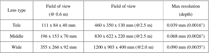
Vivid 910 employs three removable lenses with different focal distances, depending on the object sizes and measurement distances. Table 1 illustrates the relationship between the lens type, field of view and the resolution. Vivid 910 comes with Polygon Editing Tool (P.E.T) software for real time scanning and data processing. The measurement result gives the sets of points cloud data which then undergo the modeling process using RapidForm2004. RapidForm2004 is standard software for processing the laser scanning points cloud data.
Table 1: Relationship between the lens type, field of view and the resolution (Konica, 2004)
Lens type Field of view
(@ 0.6 m)
Field of view Max resolution
(depth)
Tele 111 x 84 x 40 mm 460 x 350 x 130 mm (@2.5 m) 0.039 mm (0.0016")
Middle 196 x 153 x 70 mm 830 x 622 x 220 mm (@2.5 m) 0.068 mm (0.0026")
Wide 355 x 266 x 92 mm 1200 x 903 x 400 mm (@2.0 m) 0.090 mm (0.0035")
2.0 3D MEASUREMENT AND MODELING TECHNIQUES
There are two major different methods for capturing shape in RE applications i.e. contact method and non-contact method. RE has traditionally using coordinate measurement machines (CMM) to digitise points on part surfaces. CMM are often used when high precision is required. But the disadvantages of CMM having contact to the surface of an object can damage the object and also difficult to measuring part with free-form surfaces (Ali, 2005). Non-contact methods use laser, optics and charge-couple device (CCD) sensor to capture large amounts of data in a relatively short period (Raja & Fernandes, 2008). The output of the scanning using non-contact is point cloud data set.
3.0 METHOD
Figure 2: Method 3.1 Data Capturing
In this research, the close range laser scanner was use in order to capture 3D surface of body part on 1:7.126 scales Eurocopter 350Z Prototype Helicopter Model (Figure 3). The model is 1.45 meter using for Computational Fluid Dynamic Simulation (CFD). Owing to unavailable existing drawing plan for computer simulation, it is possible to employ laser scanning techniques to regenerate the digital model in fast and accurate.
Figure 3: Eurocopter AS350Z Prototype Helicopter Model
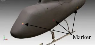
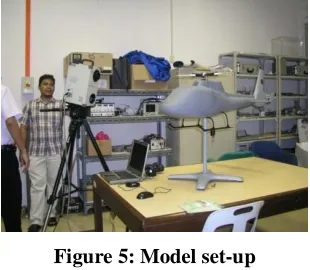
Single scanner was use in capturing object surface. Wide lens have being chosen due to object size. To enable and easy of multiple scan registration, markers were placed on top of model surface (Figure 4). The model is setup 1.6 m apart from the scanner (Figure 5). The scanning procedure consisted fix scanner and moving of studied object.
Figure 5: Model set-up
During the scanning process, Polygon Editing Tools (P.E.T) software was used to handle the data capturing. The scanned data saved in cdm file in order to transfer it to Rapidform2004 software. RapidForm2004 software is used for processing laser scanning data and generate 3D model.
The measurement procedure followed for the data collection took approximately four hours, the complete scanning of the physical model consists of total 15 scans on body part, which was processed to get a complete 3D model.
3.2 Data Processing
This stage executed processing on the scanning data to get the 3D model. It is performed in the laboratory by using high performance computer for fast processing. The developed procedure for 3D modeling using RapidForm2004 in this research comprises of point processing and polygon optimization.
In point processing stage, the point cloud data imported into RapidForm2004 software. Initially, the point cloud was imported into RapidForm2004 with 100 percent sampling rate, but it impossible the computer to process over 80 000 points cloud on single data, hence the point filtering process was required. The point filtering process consist of remove noise, filter redundancy and point smoothing executed in order to removed undesirable regions due to measurement error and reduced the number of points in a point set which are too close or overlapped each other. (Figure 6). By performing this command, the number of point cloud can be reduce about 40 percent. The process followed by converting the point cloud into mesh polygon data through triangulation process. All the mesh polygon registered and merged to get one united polygon shell. At least three pairs corresponding points used on two shells for registration and merge (Figure 7). The process resulted initial 3D polygon model with approximately 112 000 point cloud and 220 000 triangles, fair quality although many holes were visible that required optimisation.
(a) (b)
(a)
(b) (c)
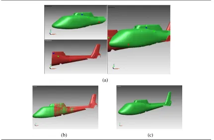
Figure 7: Registration and merging process: (a) Three pair overlapping points used for shell registration, (b) The aligned of two surfaces, (c) Merge command combined the two shells
become one united shell.
The polygon optimization process involved to fix problematic region in the initial 3D model consist of filling holes, cleaning, decimating and remesh. Fill hole function is used to remove the remain hole or gaps appear on polygon model (Figure 8). It fills the hole with new mesh surface without rearranging the triangles around the edges of the holes.
(a) (b)
Figure 8: (a) Hole or gap appear on surface, (b) Fill hole command remove the hole or gap on the surface.
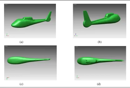
(a) (b)
(c) (d)
Figure 9: Final 3D model, (a) right view, (b) left view, (c) bottom view and (d) top view. 4.0 CONCLUSIONS
This on-going research is involved to develop procedure on scanning the object using Vivid 910 for data acquisition and data processing using RapidForm2004. It is also investigated the suitability of close range laser scanner technology to capture non-uniform 3D surface object data. The 3D model creation involved the use of RapidForm2004 software to generate body part of EUROCOPTER 350Z Generate Helicopter Model. The modeling software proved to be powerful on processing laser scanning data but computer system resources also need to be powerful. The final 3D model can be provides for surface modeling and NURBS surfacing. It also can be export to other formats such as STL, IGES and STEP which suite for others 3D design or NURBS software (RHINOCEROS, SOLIDWORKS and PRO ENGINEER). Ultimately, laser scanning technology is very useful tool as an alternative to current technologies in 3D model reconstruction.
ACKNOWLEDGMENT
The author acknowledges financial assistance for this research from Univerisiti Teknologi MARA (UiTM) and Ministry of Higher Education (MOHE) Malaysia, for Young Lecturer Scheme Scolarship and Universiti Teknologi Malaysia for research activities.
REFERENCES
Konica Minolta (2004) Non-Contact 3D Digitizer Vivid 910/VI-910 Instruction Manual.
N. S. Ali (2005) Reverse engineering of Automotive Parts Applying Laser Scanning and Structured Light Techniques, University of Tennessee.
T. Varady, R. R. Martin, J. Coxt (1997) Reverse Engineering of geometric models-an introduction, Comput. Aided Des. (4) (1997) 255-268.