Electronic Toll Collection System Using RFID
Tag
Najeeba Tabassum
M.Tech Student, Dept. of C.S., P.E.S College of Engineering, Mandya, India
ABSTRACT: The aim of this research paper is to illustrate the convenience and versatility of an automatic toll plaza system using RFID technology and its advantages over toll plazas using other techniques. With the number of vehicles increasing every year, the time and fuel wasted on waiting at the toll plazas is ever increasing. Automatic toll plazas can eliminate this wastage of time, fuel and enhance the vehicle security by providing a host of other features such as sending a text message to the registered mobile number of the owner, displaying the information about the vehicle on the display in addition to automatic opening and closing of the barricade. The toll is deducted from the vehicle owner’s prepaid account. A 125 KHz RFID reader is used for detecting the passive tags by the reader module. The motor for the barricade, on-site LCD display and GSM modules have been interfaced with the microcontroller .This system will cut down time and fuel wastage at the manually controlled toll plazas, provide a layer of security because the SMS sent and will ensure a smoother travel experience for the travellers. if the prepaid account of the vehicle doesn’t have sufficient balance the valid is allowed to pass and the vehicle owner will receive message to pay within limited time before there RFID tag gets invalid.
KEYWORDS: GSM.
I. INTRODUCTION
Our life is changing very fast and the role of automation in our day to day life is increasing at a very fast rate. This is the motive behind our project i.e. “Automation”. Day by day the number of vehicles passing over the road is increasing due to which the road condition is decaying rapidly. The government sponsors the price of road construction and road maintenance. The government has some source of money to build and maintain these roads & this source is the Toll Station. At the onset, the goal of our project group was to design an Automatic tolling system for collecting toll. After studying various techniques like weight-based systems, bar coding etc. we chose Radio frequency identification, which is an emerging technology applied for tracking and communication. RFID (Radio frequency Identification) is an area of automatic identification that has quickly been gaining momentum in recent years and has now being seen as a radical means of enhancing data handling processes, complimentary in many ways to other data capture technologies such as bar coding. In today’s era of technology, where machines are being extensively used in all the fields we are trying to emulate concept, which will be of great use in public transport systems. Today a person has to travel long distances into vastly unknown territories for job, business, or even for tourism. As the vehicles are increasing and roads are falling short, nowadays we see frequently traffic jams or long queues at the toll stations waiting for paying the toll. Paying the toll every-time through cash or checking the pass takes a lot of time. And today Time is more precious than money. Therefore our project is aimed at reducing time consumed for manual transactions and human effort.
II. RELATED WORK
In [2] Shilpa Mahajan, proposed that the system is based on infrared sensors. In this, the user has to get the IR transmitter from the main toll office. The transmitter will be charged by the store office and the data of the user will be stored in the microcontroller. When the car arrives at the toll plaza the user will have to mount the transmitter on the car and press a button to turn it on. It must be in the line of sight of the receiver. The receiver will confirm the data from the transmitter with the database and the amount of toll will get deducted. It uses a stepper motor for gate control.
In [3] Aung Myint Win, proposed that the system is based on the RFID technology. The controller used is PIC 18F4550 and has been connected with the system using USB. The RFID receiver senses the tag coming in its range and the amount gets deducted from the account of the owner after all the related information is checked from the database. The IR senses the vehicle motion for controlling the opening and closing of the gate. A stepper motor is used to control the gate. The rest of the references mentioned below have also employed the RFID technology and the working is quite similar to [3] except the database creation methods. The authors have put the GSM interfacing in their future scopes which we have implemented in our project.
III. PROPOSED SYSTEM
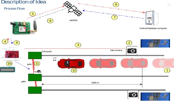
The figure. 1., contains essentially sensors, GSM module, GP Renesas microcontroller, RFID tag ,RFID reader, Android Mobiles and Power supply module. These modules are coordinated to do a solitary assignment. The proposed framework is controlled with Renesas microcontroller. At first RFID tag with driver name, phone number and prepaid account data is mounted on the vehilcle the reader scans the tag and sends the data to the reneases controller, the microcontroller checks the database and if tag is valid it sends the message using GSM to the toll collector application about amount deduction and also to the vehicle owner. of amount is not sufficient the vehicle owner receives sms to pay within a week else their tag will be invalidated, the LCD displays the command on screen and the stepper motor operates on these commands.
A. GSM Module (SIM 900)
SIM900 is a Tri-band GSM/GPRS motor that handles frequencies EGSM 900 MHz, DCS 1800 MHz and PCS 1900 MHz. SIM900 highlights GPRS multi-opening class 10/class 8 (discretionary) and bolsters the GPRS coding masterminds CS-1, CS-2, CS-3 and CS-4. You can use AT Command to get data in SIM card. The SIM interface bolsters the handiness of the GSM Phase 1 detail and in addition underpins the accommodation of the new GSM Phase 2+ affirmation for FAST 64 kbps SIM (expected for use with a SIM application Tool-kit).Both 1.8V and 3.0V SIM Cards are kept up.
The SIM interface is controlled from an inside controller in the module having obvious voltage 2.8V. All pins reset as yields driving low. The "AT" or "at" prefix must be set toward the start of each summon line. To end a charge line enter <CR>. Summons are generally trailed by a reaction that includes."<CR> <LF> <response> <CR> <LF>". All through this record, just the reactions are shown, <CR><LF> are discarded intentionally.
7
fast camera satellite
Central Database computer
Toll booth
gate
gate 1000 m
1 2 3 4 5 6 7 8 9 10
Description of Idea Process Flow
12
IV
11
B. Micro controller:
Micro controller senses the signal given from switches and decides the mode of operation i.e.recharge mode or toll collection mode. It fetches data from memory location and sends it to output devices like display, motor driver.
C. RFID tag :
RFID tag have diverse range of functions, while provides convenience, as the cards must simply be waived or tapped in front of a reader rather than swiped. These cards are used for applications as access control in security systems, time and attendance, network login security, biometric verification, cashless payment, and even event management
D. RFID reader: An RFID reader is a device that is used to interrogate an RFID tag. The reader has an inbuilt antenna that emits radio waves; the tag responds by sends back its data.
E. Liquid crystal Display: It consists of Liquid Crystal display (LCD).The display is various messages like valid card, invalid card, GSM Active , amount deducted. We are going to use 16x2 alphanumeric displays.
F. Stepper Motor: Microcontroller output is 5 volts and DC motor requires 12 volts supply. Motor driver IC is used to convert 5v to 12v, which is required to drive the motor.DC Motor is used to open the Gate barrier. This will be done when user has successfully performed the RFID swap operation with sufficient balance.
IV. RESULT
In this level incorporation of the equipment segments into Android Application. Here we are utilizing Renesas RL78 Microcontroller connecting between all Modules. GSM Module (SIM 900) used for sending information. RFID reader to read the data from RFID tag an android application at the toll collector’s system to keep track of vehicle’s data and amount deduction not only improve the passage ability of expressway but also improve the technology level of
charge. Electronic toll collection system using RFID is an effective measure to reduce management costs and fees, at the same time, greatly reduce noise and pollutant emission of toll station. In the design of the proposed Electronic toll collection (ETC) system, real time toll collection and anti-theft solution system have been designed. This reduces the manual labor and delays that often occur on roads.
Figure 2:LCD displays toll collection message
Figure 3:LCD Display for initializing of GSM modem
Figure 6: LCD Display for wrong RFID tag
F
igure 7:LCD Display NAME,AMOUNT and MOBILE NUMBER of driver
Figure 8: LCD Display balance amount Figure 9:LCD Display balance amount sent msg
Figure 10: LCD Display gate close message to stepper motor Figure 11: LCD Display pay within a week message.
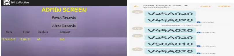
Figure 13: admin screen with records and GSM message to admin
V. CONCLUSION AND FUTURE WORK
In addition to the current work, image processing can be combined with the RFID system to make the system more reliable and secure. By combining the positives of the two we can eliminate any possible discrepancies in the system. Internet banking as well as SMS banking can be used for recharging the account of the user to make it convenient. We can also introduce new method so that the user receives the reminder that his balance is too low and can visit only 1 time so, the driver should get recharge to his account soon and also reminder message to the driver who has to pay within week.
REFERENCES
[1] Priyanka Chhoriya “Microcontroller Based Automatic Toll Collection System” http://www.ripublication.com/irph/ijict_spl/09_ijict v3n8spl.pdf
[2] Sachin Bhosale 1,Dnyaneshwar Natha Wavhal2. “Automated Toll Plaza System using RFID” IJSETR, Vol 2,Issue 1, Jan 2013.
[3] Asif Ali Laghari1, M. Sulleman Memon2 and Agha Sheraz Pathan3,“RFID Based Toll Deduction System,”I.J. Information Technology and
Computer Science, 2012, 4, 40-46
[4] Abhishek Sharma1, Arpit Yadav2 , Anurag PArmar 3, AUTOMATIC TOLL SYSTEM, 2014 IJIRT | Volume 1 Issue 6.
[5] Satyasrikanth P1, Mahaveer Penna2, Dileep Reddy Bolla3 AUTOMATIC TOLL COLLECTION SYSTEM USING RFID IJCSMC, Vol. 5, Issue. 8, August 2016, pg.247 253
[6]Le Minh Kieu, Ashish Bhaskar, and Edward Chung. Passenger Segmentation Using Smart Card Data. IEEE transactions on intelligent transportation systems, Vol. 16, NO. 3, June2015
BIOGRAPHY