i
SEGMENTED EXCITATION FOR ELECTRICAL CAPACITANCE TOMOGRAPHY
SHAHRULNIZAHANI BT MOHAMMAD DIN
A thesis submitted in fulfilment of the requirements for the award of the degree of
Master of Engineering (Electrical)
Faculty of Electrical Engineering Universiti Teknologi Malaysia
iii
iv
ACKNOWLEDGEMENT
Firstly, I want to express my deepest gratitude to my adorable supervisor; Dr. Leow Pei Ling who has guided me through this journey. I will cherish her useful comments, remarks and engagement through the learning process. Without her guidance and persistent help this dissertation would not have been possible. I would like to thank Prof. Dr. Ruzairi Abdul Rahim and PROTOM-i, who opened the door of opportunity and believe in me. For me, this is just a beginning, there are a lot more to be discovered and to be explored.
Apart from the efforts, the success of any project depends largely on the encouragement and guidelines of many others. I take this opportunity to express my gratitude to the people who have been instrumental in the successful completion of this project. To my parents, my better half and my children, thank you for understandings, supports, and I will be grateful forever for your love.
Not forgetting to my friends who always been there; Chee Pei Song, Mas Elyza, Amir Sidek, Prakash Vellayan, Aizat Azmi, Nur Syazana, Dr. Elmy Johana Mohamad, Siti Hajar Abdul Mutalib and others. Thank you very much for being with me through thick and thin and moral support, strength, and for everything.
v
ABSTRACT
vi
ABSTRAK
vii
TABLE OF CONTENTS
CHAPTER TITLE PAGE
DECLARATION ii
DEDICATION iii
ACKNOWLEDGEMENT iv
ABSTRACT v
ABSTRAK vi
TABLE OF CONTENTS vii
LIST OF TABLES x
LIST OF FIGURES xi
LIST OF ABBREVIATIONS xiii
LIST OF SYMBOLS xiv
LIST OF APPENDICES xv
1 INTRODUCTION
1.1 Introduction 1
1.2 Types of Tomography 3
1.3 Electrode Sensor Installation for ECT 5
1.4 Problem Statement 6
1.5 Objectives of Research 7
1.6 Research Scope 7
1.7 Thesis Structure 7
2 LITERATURE REVIEW
2.1 Introduction 9
2.2 Electrical Capacitance Tomography (ECT). 9
2.2.1 Capacitance Measurement 10
2.2.2 Dielectric Materials 11
2.2.3 Permittivity 11
2.2.3.1 Series Permittivity Model 12 2.2.3.2 Parallel Permittivity Model 13 2.2.3.3 Maxwell Permittivity Model 14
2.3 ECT System Components 14
viii
2.5 Advantages of ECT 17
2.6 Disadvantages of ECT 18
2.7 Types of Projection 19
2.8 Normalisation of Measured Capacitance and Permittivity
20 2.9 Construction of Permittivity Distribution Images 23 2.10 The Linear Back Projection (LBP) Algorithm 24
2.10.1 The Forward Problem 25
2.10.2 The Inverse Problem 25
2.11 Image Reconstruction using Standard Deviation 26
2.12 Number of Electrodes 27
2.13 ECT Protocol Method 28
2.14 Segmented Excitation Method 29
2.15 Electrical Field Modelling 30
2.16 Simulation Tool : COMSOL Multiphysics 33
2.17 Summary 34
3
CHARACTERIZATION EVALUATION OF SINGLE VERSUS SEGMENTED EXCITATIONS
3.1 Introduction 35
3.2 16-Electrode ECT Sensor 35
3.3 2D ECT System Modeling 37
3.4 Evaluation of Single and Segmented Excitation 44 3.4.1 Electrical Potential Distribution within
Pipeline for Single and Segmented Excitation
45
3.4.2 Evaluation of Voltage Value at The Center Of The Pipe
48 3.4.3 Electrical Potential at the Centre of the Pipe
for Various Segmented Excitations
54 3.4.4 Electrical Field Simulation 57
3.5 Summary 60
4 RECONSTRUCTION OF 16-ECT SENSITIVITY MAP
4.1 Introduction 61
4.2 The Image Reconstruction Model 61
4.3 Image Reconstruction Process Flow 64
4.4 Data Processing 65
4.5 Data Plotting 66
4.6 Mapping the Raw data 69
4.7 Ensemble Images 74
4.8 Normalisation Process for Image Reconstruction 77
4.9 Threshold Process 78
ix
5 CONCLUSION AND FUTURE WORK
5.1 Conclusions 82
5.2 Recommendations for future work 84
REFERENCES 85
x
LIST OF TABLES
TABLE NO. TITLE PAGE
1.1 Electrical Tomography application and measurement properties
2
3.1 The parameter of the ECT system 36
3.2 The switching method for Single and Segmented excitation
45
3.3 The Non-elapse and Elapse Segmented Excitation methods.
46
3.4 The dimension of each electrode for different ECT system 49
3.5 The excitation dimension for ECT models 50
3.6 The comparison of ECT models for Single Excitation 51 3.7 Voltage value at the center of the pipe of ECT models 52 3.8 The electrical potential at the center of the pipe for 50% of
total electrode length.
53
3.9 The excitation method of various segmented excitations 55 3.10 The results from various segmented switching 56
4.1 Different concentration of water-oil [21] 62
4.2 The switching method of Single and Segmented Excitation
64
4.3 The electrical potential value from the normalization images
xi
LIST OF FIGURES
FIGURE NO. TITLE PAGE
1.1 Internal and external electrodes installation 5
2.1 The polarization of dielectric material 11
2.2 The series permittivity model 12
2.3 The parallel permittivity model 13
2.4 ECT Schematic diagram 15
2.5 Parallel and fan-beam projections 19
2.6 Normalised capacitance graph 22
2.7 Normalised permittivity graph 22
2.8 The 16-electrode ECT system pixel grid (32 ⨯ 32 pixels) 24 2.9 Bulge electrical field of ECT setup with a two phase flow 31
3.1 The existing ECT System 36
3.2 Flow of COMSOL Multiphysics modelling 37
3.3 The electrode of ECT [21]. 38
3.4 The arrangement and configuration of ECT electrode [71]. 38
3.5 The model of ECT using AUTOCAD 2010 39
3.6 A sketch of a mesh 40
3.7 Initial mesh for ECT model 40
3.8 Finer mesh of ECT 41
3.9 The boundary and sub-domain setting 42
3.10 Indication of the electrodes 44
3.11 Electrical potential and field for (a) Single and (b) Segmented Excitation
47
3.12 The ECT model at the center of the drawing 48
xii
systems
3.14 The tendency of voltage value at the center of the pipe 53 3.15 Electrical potential at the center of the pipe from various
excitations method.
57
3.16 ECT Model with water droplets 58
3.17 Electrical field for single excitation 58
3.18 The comparison of Single (a) and Segmented (b) Excitation method
59
4.1 Experiment of water-oil flow and image reconstruction [21].
62
4.2 The ECT model 63
4.3 The flow of image reconstruction 65
4.4 32 × 32 grid in COMSOL Multiphysics 66
4.5 The 1st switching for Single Excitation 67
4.6 The 2nd switching for Single Excitation 67
4.7 The 3rd switching for Single Excitation 68
4.8 The 1st switching for Segmented Excitation 69
4.9 The raw data arrangement for data mapping 70
4.10 The mapping image for 1st switching of Single Excitation. 70 4.11 The 2nd and 3rd switching for Single Excitation 71
4.12 The Single Excitation arrangement data 72
4.13 The Segmented Excitation arrangement data 73
4.14 The summation method for same pixel position 74
4.15 Single Excitation ensemble images 75
4.16 Segmented Excitation ensemble images 76
4.17 Normalisation Result for Single and Segmented Excitation method
77
4.18 Segmentation for threshold 79
4.19 The threshold for Single and Segmented Excitation method.
79
xiii
LIST OF ABBREVIATIONS
° - Degree
AC/DC - Alternatice Current/ Direct Current CMOS - Complementary Metal Oxide
Semiconductor CT - Clinical Tomography DAS - Data Acquisition System DMT - Dual Modality Tomography
ECT - Electrical Capacitance Tomography EIT - Electrical Impedance Tomography EMT - Electromagnetic Tomography ERT - Electrical Resistance Tomography LBP - Linear Back Projection
MIT - Magnetic Induction Tomography MRI - Magnetic Resonance Imaging PET - Positron Emission Tomography SNR - Signal to Noise Ratio
xiv
LIST OF SYMBOLS
Q - Charge
V - Volatge
C - Capacitance
ℰr - Relative static permittivity ℰ0 - Electric constant
d - Separation between the plates
ℰS - Relative permittivity for series model
CS - Capacitance for series model
A - Area of cross-section of the electrodes x - Height/length of k level
ℰP - Relative permittivity for parallel model CP - Capacitance for parallel model
CN - Normalise capacitance value.
CLA - Capacitance measured at higher permittivity
CHA - The absolute value of the measured capacitance during the calibration
KHA - Pixel permittivity at higher permittivity KLA - Pixel permittivity at lower permittivity
φ - Electrical potential N - Number of electrode
M - Independent measurement
P - Protocol
E - Electrical field
F - Electrical force
R1 - Inner diameter R2 - Outer diameter 𝜌 - Radius ratio
𝜎 - Standard deviation
x - Each value in the population
xv
LIST OF APPENDICES
APPENDIX. TITLE PAGE
A Potential Graph for Single Excitation 90
B Potential Graph for Segmented Excitation 93
1
1. CHAPTER 1
INTRODUCTION
1.1 Introduction
Tomography means as slices of pictures [1]. From The Oxford English Dictionary, Tomography is defined as „Radiography in which an image of a predetermined plane in the body or other object is obtained by rotating the detector and the source of radiation in such a way that points outside the plane give a blurred image [2]. Process tomography consists of non-intrusive or intrusive tomographic imaging systems to measure multi-component mixtures in a process vessel or pipeline [1]. For intrusive tomographic technique, the measurement electrode penetrates the pipe wall to obtain the desired signal with direct contact with the flow, whereas for non-intrusive tomographic technique is based on measurement signal from sensors mounted away from the flow. Practically, these sensors are mounted at the periphery of the pipe wall [3]. The system helps to understand the flow distribution inside closed pipe or vessel by detecting the variation of dielectric permittivity [4].
In 1970‟s, tomography was applied for medical diagnostic imaging [5]. The article also reported that x-ray imaging was developed in 1980‟s to allow scanning internal structure (bones) of human‟s body safely and non-invasively. Later, in 1990‟s tomography has been progressively developed and it was introduced to manufacturing and processes to inspect closed section including food industry, chemical, petrochemical, food and biochemical industries [6]. The article also reported that the development of tomography in industry is driven by the needs and
2
requirement to inspect the process, to adopt resources efficiently, and to fulfill requirement and for inspection of quality control.
Driven from the demand, the rapid development of tomography is beyond medical applications. There are two types of tomography; electrical tomography method and radiation-based method tomography [7].
Electrical tomography method has gained its popularity more than 10 years ago [7]. Electrical tomography approach suits industrial requirements with detection method and the measurement properties. For instance, resistance tomography is used to determine the distribution of conductivity, capacitance tomography offers detection of different permittivity, and distribution of permeability is detected by inductance tomography. Impedance tomography helps to measure both resistive and reactive components. York [8] also reported that electrical tomography is able to improve profits by reducing process cycle time and waste management. The electrical tomography properties [3] and applications are described in Table 1.1.
Table 1.1: Electrical Tomography application and measurement properties
3
Another segregation of tomography is the radiation-based method [9]. This method uses infrared, microwave, X rays, gamma rays, neutrons, magnetic resonance, ultrasound or acoustics as the sensor. These methods are quite expensive and required long data collection periods and hence, is not suitable for real-time behavior process monitoring. However, these methods provide high spatial resolution which is more suitable and beneficial for medical measurement and applications.
1.2 Types of Tomography
The determination of the type of sensors used need to consider the purpose of the inspection, the need, the output or the information of the process, as well as the size and environment of the process [1]. The other considerations are depending on the properties or characteristics of the flow material that is being examined and the flow state (gas, liquid, solid) [10]. Process tomography systems are normally classified according to the sensor used.
Ultrasonic imaging tomography is one of radiation-based method and commonly used to visualize body structure including muscles, tendons, vessels, joints, and internal organs. It applies very high wave frequency sound wave to inspect the process. Nowadays ultrasonic imaging is also applied in industrial application [11].
Positron emission tomography (PET) produces a three- dimensional image or picture of body function [12]. The body needs to be emitted indirectly with gamma rays. Images of space inside the body are reconstructed using computer analysis. PET is a Computed Tomography (CT) X-ray is widely used in medical application nowadays.
4
electrodes which allow it to produce images of the permittivity or conductivity of part of the body‟s part. The process may be repeated for different current configurations, depends on the measurement needed. The purpose of inspection is to reconstruct image of an internal structure or specific organ [13].
Another type of electrical tomography is Electrical Capacitance Tomography (ECT). ECT applies arrays of electrodes to produce images in closed pipe or vessel. ECT is popular for its simple design, fairly cheap and fast response. ECT system design also allows portability and flexibility in excitation and therefore is the most applied process tomography system in the industry [14]. However, ECT produces low resolution problem due to its soft-field effect.
Magnetic Induction Tomography (MIT) applies by inducing eddy current from excited magnetic coil to produce image electromagnetic properties of an object. This non-destructive test is also known as eddy current tomography, electromagnetic tomography (EMT), eddy current testing and electromagnetic induction tomography [15].
Optical tomography system is an emerging modality as it provides straightforward, inexpensive and has a better dynamic response than other radiation-based tomographic techniques such as x-ray and positron emission tomography. This modality also could perform on high-speed particles due to wide bandwidth coverage [16].
5
1.3 Electrode Sensor Installation for ECT
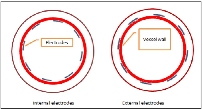
The main sensor used for electrical tomography is based on the sensor installation. The electrodes can be mounted internally or externally of the pipe. It‟s depends on the material of the pipe wall. If the vessel wall is a non-conducting material, the sensors can be located inside or outside the pipe. On the other hand, if the pipe wall is a conductor, the sensors need to be installed inside the pipe [17]. The configuration of inside and outside the pipe is illustrated in Figure 1.1.
Figure 1.1: Internal and external electrodes installation
External electrodes are non-intrusive and providing simpler design and fabrication procedure. The sensor is not affected by extremely high pressure, temperature and turbulences in the pipe. This method also could avoid any contamination on the electrodes from the fluid or material inside the vessel. However, the external electrode fabrication suffers from the disadvantage of nonlinearity characteristics. The capacitance value varies based on the vessel wall thickness [2]. Practically, the wall thickness is determined by the pressure limitations, usually the wall thickness is between 2 to 4 mm [18].
6
characteristics. The capacitance value change is directly proportionate with the permittivity change inside the vessel [2].
For ECT, the common installation of sensor is mounted outside the pipe [19, 20]. The sensors do not directly contact with the materials inside the pipe. ECT is a non-invasive and non-intrusive measurement technique. Gamio et. al. [21] elaborated the advantages of tomographic images are invasive and non-intrusive. The term non-invasive can be described as the system does not disrupt the walls of the pipe wall, for example the installation of the probes. Non-intrusive disturb or distract the process that being tested. ECT has been widely used in many industrial applications such as oil and gas industry, petrochemical, chemical related industry due to its low cost and the flexibility of the design and installation [21]. However, ECT inherits the soft-field nature which contributes to low resolution image reconstruction [22].
1.4 Problem Statement
7
1.5 Objectives of Research
The main objective of this research is to study the capability of segmented excitation method to improve the resolution of ECT imaging by comparing the electrical potential of the ECT system between single and segmented excitation method. The specific objectives of the research are listed as follows:
1. To investigate the performance of segmented excitation method for improving image resolution, particularly at the center of the pipe.
2. To reconstruct the sensitivity map from simulation of electrical capacitance tomography system for comparing the effectiveness of multiple segmented excitation method.
1.6 Research Scope
In this project, the ECT system is modeled and simulated using numerical modeling method. The model of the ECT system is based on actual existing system in the lab and the designing of ECT will be made using COMSOL Multiphysics 4.0. The main objective of the project is to investigate the pattern distribution of electrical potential and electrical field inside the pipe. Different configuration of segmented excitation was studied to investigate the feasibility of this method to improve the resolution of tomogram images.
1.7 Thesis Structure
8
In Chapter 1 – Introduction discusses the introduction of the project. The categorized of tomography is listed and discussed briefly. The research problem and research objective is stated as well as the scope of the project.
Chapter 2 – Literature Review elaborates the ECT system and its applications. The discussion of the model of permittivity and the classifications of tomography modality are stated in this chapter. The advantages and disadvantages as well as the challenges of ECT are described intensively.
Chapter 3 – Characterization evaluation of single versus segmented excitations. The chapter discusses the simulation processes as well as the data processing is discussed. The analysis of the electrical field distribution as well as electrical potential for ECT system models will be presented.
Chapter 4 - Reconstructing of 16-ECT Sensitivity Map. This chapter describes the detail process flow to reconstruct the sensitivity map from simulation data of COMSOL Multiphysics.
85
REFERENCES
[1] R. A. Williams and M. S. Beck, Process Tomography: Principles, Techniques, and Applications: Butterworth-Heinemann, 1995.
[2] S. S. Donthi, "Capacitance based Tomography for Industrial Applications," Credit seminar report : Electronic Systems Group, pp. 1-18, 2004.
[3] F. Wang, Q. Marashdeh, L.-S. Fan, and R. A. Williams, "Electrical Capacitance, Electrical Resistance, and Positron Emission Tomography Techniques and Their Applications in Multi-Phase Flow Systems," in Advances in Chemical Engineering. vol. Volume 37, L. Jinghai, Ed., ed: Academic Press, 2009, pp. 179-222.
[4] L. F. M. Moura, E. Cenedese, and A. C. A. Filho, "Numerical Study Of A Capacitive Tomography System For Multiphase Flow," Engenharia Térmica (Thermal Engineering), vol. 8, pp. 67-78, 2009.
[5] W. R. Hendee, "Cross Sectional Medical Imaging: A History," RadioGraphics, vol. 9, pp. 1155-1180, 1989.
[6] M. S. Beck and R. A. Williams, "Process Tomography: A European Innovation and Its Applications," Measurement Science and Technology, vol. 7, pp. 215–224, 1996.
[7] D. Wolf, A. Lubk, F. Röder, and H. Lichte, "Electron Holographic Tomography," Current Opinion in Solid State and Materials Science, vol. 17, pp. 126-134, 2013.
[8] T. York, "Status of electrical tomography in industrial applications," Journal of Electronic Imaging, vol. 10, pp. 608-619, 2001.
[9] J. Abdullah, M. C. F. Cassanello, M. P. Dudukovic, T. Dyakowski, M. M. Hamada, J. H. Jin, et al., "Industrial Process Gamma Tomography," International Atomic Energy Agency, 2008.
[10] B. S. Hoyle, Hugh McCann, and D. M. Scott, "Process Tomography," in Process Imaging for Automatic Control, ed, 2001, pp. 85-126.
[11] Y. Abdul Wahab, M. A. Ahmad, R. Abdul Rahim, and M. H. Fazalul Rahiman, "Application of transmission-mode ultrasonic tomography to identify multiphase flow regime," in Electrical, Control and Computer Engineering (INECCE), 2011 International Conference on, 2011, pp. 119-123.
[12] Y. Kovalchuk and V. Callaghan, "A Self-Organizing System for Online Maintenance of a Living Organism," in Intelligent Environments (IE), 2010 Sixth International Conference on, 2010, pp. 283-288.
[13] N. Bahrani, "2 1/2 D Finite Element Method for Electrical Impedance Tomography Considering the Complete Electrode Model," M.Eng, Electrical and Computer Engineering, Carleton University, Canada, 2012.
[14] N. Flores, J. C. Gamio, C. Ortiz-Alemán, and E. Damián, "Sensor Modeling for an Electrical Capacitance Tomography System Applied to Oil Industry," in Excerpt from the Proceedings of the COMSOL Multiphysics User's Conference, 2005.
[15] H. Griffiths, "Magnetic Induction Tomography," Measurement Science and Technology, vol. 12, p. 1126, 2001.
86
[17] P. T. Ltd. (2009). Electrical Capacitance Tomography System Type TFLR5000 Operating Manual, Fundamentals of ECT.
[18] S. Matej and R. M. Lewitt, "Image Representation and Tomographic Reconstruction Using Spherically-Symmetric Volume Elements," in IEEE Conference Record of the Nuclear Science Symposium and Medical Imaging Conference, 1992, pp. 1191-1193.
[19] X. Dong and S. Guo, "Modelling an Electrical Capacitance Tomography Sensor with Internal Plate Electrode," in International Conference on Test and Measurement, 2009. , 2009, pp. 160-163
[20] E. J. Mohamad, "A Segmented Capacitance Tomography for Visualising Material Distributions in Pipeline Conveying Crude Palm Oil," PhD, Faculty of Electrical Engineering, Universiti Teknologi Malaysia, 2012.
[21] J. C. Gamio, "A Comparative Analysis of Single And Multiple-Electrode Excitation Methods in Electrical Capacitance Tomography," Measurement Science and Technology, vol. 13, pp. 1799–1809, 2002.
[22] A. S. Al-Afeef, "Image Reconstructing in Electrical Capacitance Tomography of Manufacturing Processes Using Genetic Programming," Master Degree, Faculty of Graduate Studies, Al-Balqa Applied University, Jordan, 2010.
[23] W. Smolik, "Reconstruction of complex objects in electrical capacitance tomography," in Imaging Systems and Techniques, 2009. IST '09. IEEE International Workshop on, 2009, pp. 432-437.
[24] R. M. Timothy and S. P. Todd, "The Influence of Permittivity Models on Phantom Images Obtained From Electrical Capacitance Tomography," Measurement Science and Technology, vol. 13, p. 1822, 2002.
[25] Z. Fan and R. X. Gao, "A new sensing method for Electrical Capacitance Tomography," in Instrumentation and Measurement Technology Conference (I2MTC), 2010 IEEE, 2010, pp. 48-53.
[26] K. Zainal-Mokhtar and J. Mohamad-Saleh, "A Generic Intelligent Oil-Gas Flow Classifier Based On ECT Sensor Data," International Journal of Innovative Computing, Information and Control ICIC, vol. 8, pp. 953-965, 2012.
[27] K. Wang, R. Su, A. A. Oraevsky, and M. A. Anastasio, "Investigation of iterative image reconstruction in three-dimensional optoacoustic tomography," Physics in Medicine and Biology, pp. 1-38, 2012.
[28] N. LI, Y. HAN, and J. JIAO, "Influence of Capacitive Sensor Geometric Design on Liquid Membrane Detection " in Advance Scientific Program, 2013.
[29] E. Dubrofsky and R. J. Woodham, "Combining Line and Point Correspondences for Homography Estimation," 4th International Symposium on Visual Computing, pp. 202–213, 2008.
[30] W. Q. Yang and P. Lihui, "Image Reconstruction Algorithms for Electrical Capacitance Tomography," Measurement Science and Technology, vol. 14, p. R1, 2003.
87
[32] P. Waje and N. Warke, "Review: Electrical Capacitance Tomography," International Journal of Engineering Research and Applications, pp. 49-53, 2012.
[33] B. B. Abraham and G. Anitha, "Designing of Lab View Based Electrical Capacitance Tomography System for the Imaging of Bone Using NI ELVIS and NI USB DAQ 6009 " Bonfring International Journal of Power Systems and Integrated Circuits, vol. 2, 2012.
[34] G. Hahn, J. Dittmar, A. Just, and G. Hellige, "Improvements in the Image Quality of Ventilatory Tomograms by Electrical Impedance Tomography," Physiological Measurement, vol. 29, p. S51, 2008.
[35] F. Fu, M. Kong, C. Xu, C. Liang, and ShiminWang, "Flow Characterization of Dense-Phase Pneumatic Conveying System of Pulverized Coal through Electrostatic Sensor Arrays," Advances in Mechanical Engineering, vol. 2013, pp. 1-13, 2013.
[36] Z. Gut, P. Wolanski, and P. Oleszczak, "Monitoring Of Combustion Processes in Industrial Burners Using Electrical Capacitance Tomography " Journal of KONES Powertrain and Transport, vol. 18, pp. 117-121, 2011 [37] F. Wang, Q. Marashdeh, L. S. Fan, and W. Warsito, "Electrical Capacitance
Volume Tomography: Design And Applications," Sensors (Basel), vol. 10, pp. 1890-917, 2010.
[38] X. Song, "Statistical Analysis and Evaluation of Near Infrared Tomographic Imaging System " PhD, Thayer School of Engneering Dartmouth College, Hanover, New Hampshire, 2005.
[39] S.-W. Chen, L. K. Wang, and J.-H. Lan, "Moving Object tracking Based on Background Subtraction Combined Temporal Difference," in International Conference on Emerging Trends in Computer and Image Processing (ICETCIP'2011) Bangkok, 2011, pp. 16-19.
[40] H. B. Kekre and K. Patil, "Standard Deviation of Mean and Variance of Rows and Columns of Images for CBIR," World Academy of Science, Engineering and Technology, vol. 27, pp. 609-612, 2009.
[41] Q. Marashdeh, W. Warsito, a. Liang-Shih Fan, and S. M. Fernando L. Teixeira, IEEE, "A Multimodal Tomography System Based on ECT Sensors," IEEE Sensors Journal, vol. 7, pp. 426-433, 2007.
[42] Y. Yang and L. Peng, "Data Pattern With ECT Sensor and Its Impact on Image Reconstruction," Sensors Journal, IEEE, vol. 13, pp. 1582-1593, 2013.
[43] H. Wang, I. Fedchenia, S. Shishkin, A. Finn, L. Smith, and M. Colket, "Electrical Capacitance Tomography: A Compressive Sensing Approach," in 2012 IEEE International Conference on Imaging Systems and Techniques (IST), 2012, pp. 590-594.
[44] R. A. Rahim, L. C. Leong, K. S. Chan, M. H. F. Rahiman, and J. F. Pang, "Solid/Gas Concentration Measurements Using Multiple Fan Beam Optical Tomography," The Open Optics Journal, vol. 2, pp. 21-34, 2008.
[45] C. Gamio, "Electrical capacitance tomography two-phase oil-gas pipe flow imaging by the linear back-projection algorithm," Geofísica Internacional, vol. 44, pp. 265-273, 2005.
88
[47] E. J. Mohamad, R. A. Rahim, P. L. Leow, M. H. Fazalul Rahiman, O. M. F. Marwah, N. M. Nor Ayob, et al., "An introduction of two differential excitation potentials technique in electrical capacitance tomography," Sensors and Actuators A: Physical, vol. 180, pp. 1-10, 2012.
[48] W. Q. Yang and S. Liu, "Electrical Capacitance Tomography with Square Sensor," Electronics Letters, vol. 35, pp. 295-296, 1999.
[49] I. Øyvind, "A review of reconstruction techniques for capacitance tomography," Measurement Science and Technology, vol. 7, p. 325, 1996. [50] L. P. Urimi, "Image Reconstruction Techniques and Measure of Quality:
Classical Vs. Modern Approaches," Master Degree, Faculty of the Graduate School University of Maryland, 2005.
[51] W. Guobao, L. Changqing, S. R. Cherry, and Q. Jinyi, "Statistical image reconstruction for hybrid fluorescence optical tomography and positron emission tomography," in Biomedical Imaging: From Nano to Macro, 2011 IEEE International Symposium on, 2011, pp. 488-491.
[52] Y. Wuqiang, "Design of electrical capacitance tomography sensors," Measurement Science and Technology, vol. 21, p. 042001, 2010.
[53] L. Peng, J. Ye, G. Lu, and W. Q. Yang, "Evaluation of Effect of Number of Electrodes in ECT Sensors on Image Quality," Sensors Journal, IEEE, vol. 12, pp. 1554-1565 2012.
[54] L. Peng, C. Mou, D. Yao, B. Zhang, and D. Xiao, "Determination of the Optimal Axial Length of the Electrode in an Electrical Capacitance Tomography Sensor," Flow Measurement and Instrumentation, vol. 16, pp. 169-175, 2005.
[55] Z. Fan, R. X. Gao, and J. Wang, "Virtual Instrument for Online Electrical Capacitance Tomography," in "Practical Applications and Solutions Using LabVIEW™ F. Silviu, Ed., ed: Intech, 2011, pp. 3-16.
[56] K.-J. J. Alme and S. Mylvaganam, "Comparison of Different Measurement Protocols in Electrical Capacitance Tomography Using Simulations," IEEE Transactions on Instrumentation and Measurement, vol. 56, pp. 2119-2130 2007.
[57] A. M. Olmos, M. A. Carvajal, D. P. Morales, A. García, and A. J. Palma, "Development of an Electrical Capacitance Tomography System Using Four Rotating Electrodes," Sensors and Actuators A: Physical, vol. 148, pp. 366-375, 2008.
[58] Z. Fan and R. X. Gao, "Enhancement of Measurement Efficiency for Electrical Capacitance Tomography," IEEE Transactions on Instrumentation and Measurement, vol. 60, pp. 1699-1708, 2011.
[59] S. M. Din, S. H. Mutalib, R. A. Rahim, E. J. Mohamad, R. A. Rahim, and P. L. Leow, "Multiple Fan Beam Segmented Excitation for ECT System," in Progress in Process Tomography & Instrumentation System – Series 11, ed, 2012, pp. 1-15.
[60] L. Lanying, G. Ming, and C. Deyun, "A novel multiple-electrodes excitation method for electrical capacitance tomography system," in 2011 6th International Forum on Strategic Technology (IFOST), 2011, pp. 1167 - 1171.
89
[62] M. A. Zimam, E. J. Mohamad, R. A. Rahim, and L. P. Ling, "Sensor Modelling of ECT using COMSOL Mutiphysics," Jurnal Teknologi, vol. 55, pp. 33-47, 2011.
[63] L. F. C. Jeanmeure, T. Dyakowski, W. B. J. Zimmerman, and W. Clark, "Direct Flow-Pattern Identification Using Electrical Capacitance Tomography," Experimental Thermal and Fluid Science, vol. 26, pp. 763-773, 2002.
[64] A. Fuchs and H. Zangl, "Simulation-Based Analysis of the Spatial Sensitivity Function of an Electrical Capacitance Tomography System," in Excerpt from the Proceedings of the COMSOL Users Conference, 2007.
[65] S. Oh and R. Sadleir, "Sensitivity Distribution Field of Electrical Impedance Tomography," in Excerpt from the Proceedings of the COMSOL Multiphysics User's Conference 2005, pp. 1-5.
[66] J. Abbaszadeh, H. A. Rahim, R. A. Rahim, and S. Sarafi, "Ultrasonic Tomography System: Optimizing the Frequency in a Metal Pipe Conveyor," Applied Mechanics and Materials Vols. , pp. 572-576, 2013.
[67] Elmy Johana, F. R. M. Yunus, R. A. Rahim, and K. S. Chan, "Hardware Development of ECT for Imaging a Mixture of Water and Oil," Jurnal Teknologi, vol. 54 Special Edition, pp. 425–442, 2011.
[68] E. J. Mohamad, R. Rahim, R. Abdull, L. P. Ling, M. H. F. Rahiman, O. M. F. Marwah, et al., "Segmented Capacitance Tomography Electrodes: A Design and Experimental Verifications," Sensors Journal, IEEE, vol. 12, pp. 1589-1598 2012.
[69] E. J. Mohamad, O. M. F. Marwah, R. Rahim, R. Abdull, M. H. F. Rahiman, and S. Z. M. Muji, "Electronic Design for Portable Electrical Capacitance Sensor: A Multiphase Flow Measurement," in 2011 4th International Conference On Mechatronics, 2011, pp. 1-8.
[70] W. Xiong, "Applications of COMSOL Multiphysics Software to Heat Transfer Processes.," Master Degree, Department of Industrial Management, Arcada University of Applied Sciences, 2010.