Electronic Theses and Dissertations Theses, Dissertations, and Major Papers
2012
A 77 GHz Reconfigurable Micromachined Microstrip Antenna
A 77 GHz Reconfigurable Micromachined Microstrip Antenna
Array
Array
Ismail Hamieh
University of Windsor
Follow this and additional works at: https://scholar.uwindsor.ca/etd
Recommended Citation Recommended Citation
Hamieh, Ismail, "A 77 GHz Reconfigurable Micromachined Microstrip Antenna Array" (2012). Electronic Theses and Dissertations. 128.
https://scholar.uwindsor.ca/etd/128
Antenna Array
by
Ismail Ali Hamieh
A Thesis
Submitted to the Faculty of Graduate Studies through Electrical and Computer Engineering in Partial Fulfillment of the Requirements for the Degree of Master of Applied Science at the
University of Windsor
Windsor, Ontario, Canada
2012
Antenna Array
by
Ismail Ali Hamieh
APPROVED BY:
______________________________________________ Dr. Afsaneh Edrisy, Outside Department Reader Mechanical Automotive & Manufacturing Engineering
______________________________________________ Dr. Kemal Tepe, Department Reader
Department of Electrical & Computer Engineering
______________________________________________ Dr. Sazzadur Chowdhury, Advisor
Department of Electrical and Computer Engineering
______________________________________________ Dr. J. Wu , Chair of Defense
DECLARATION OF ORIGINALITY
I hereby certify that I am the sole author of this thesis and that no part of this
thesis has been published or submitted for publication.
I certify that, to the best of my knowledge, my thesis does not infringe upon
anyone’s copyright nor violate any proprietary rights and that any ideas, techniques,
quotations, or any other material from the work of other people included in my thesis,
published or otherwise, are fully acknowledged in accordance with the standard
referencing practices. Furthermore, to the extent that I have included copyrighted
material that surpasses the bounds of fair dealing within the meaning of the Canada
Copyright Act, I certify that I have obtained a written permission from the copyright
owner(s) to include such material(s) in my thesis and have included copies of such
copyright clearances to my appendix.
I declare that this is a true copy of my thesis, including any final revisions, as
approved by my thesis committee and the Graduate Studies office, and that this thesis has
ABSTRACT
A micromachined silicon based MEMS single-pole-Single-Throw (SPST)
switches embedded reconfigurable microstrip antenna array for use in a 77 GHz tri-mode
automotive collision avoidance radar is presented. The emphasis is put on compact 77
GHz micromachined microstrip antenna array, capable of being integrated with silicon
base Rotman lens that provides an intrinsic beamforming capability without any
microelectronic signal processing.
The first part of this thesis deals with the theory behind microstrip antennas and a
deep explanation of antenna arrays. The second part of the thesis is concerned with
design procedures and considerations. It provides a detailed study of how to design and
fabricate an inset fed rectangular micromachined microstrip patch antenna array using
XFDTD 3-D software and study the effect of antenna dimensions.
At last, this thesis shows the simulation results that by incorporating a
micromachined technology into microstrip antenna array we are able to achieve higher
DEDICATION
This thesis is dedicated to my parents who have supported me all the way since
the beginning of my studies. Also, it is dedicated to my wife and my daughter, Wadad
ACKNOWLEDGEMENTS
I would like to express my appreciation to my advisory committee: Dr. Sazzadur
Chowdhury, Dr. Kemal Tepe, and Dr. Afsaneh Edrisy. Thanks for giving me the
opportunity to be part of the University of Windsor research MEMS group. Special
thanks to Dr. Chowdhury for his time, patience, and understanding. Also, thanks to the
Auto21 and CMC, Canadian research and development community, for making this study
possible by providing its funding to the University of Windsor.
The most special thanks go to my best partner and friend, my wife. Wadad, you
gave me your unconditional support and love through all this long process. I express my
thanks and appreciation to my family for their understanding, motivation and patience.
Lastly, but in no sense the least, I am thankful to all colleagues and friends who made my
TABLE OF CONTENTS
DECLARATION OF ORIGINALITY ... iii
ABSTRACT ... iv
DEDICATION...v
ACKNOWLEDGEMENTS ... vi
LIST OF TABLES ...x
LIST OF FIGURES ... xi
LIST OF ABBREVIATIONS ...xv
NOMENCLATURE ... xvii
CHAPTER I. INTRODUCTION 1.1 Problem Statement ...1
1.2 Automotive radar ...5
1.2.1 Electronically scanned radar ...5
1.2.2 The MEMS radar ...7
1.2.3 MEMS radar principle of operation ...10
1.3 Research hypothesis...11
1.4 Motivation ...12
1.5 Principal Results ...13
1.6 Thesis Organization ...14
II. REVIEW OF LITERATURE 2.1 Literature Review ...15
2.1.1 MEMS technology ...17
2.1.2 Radar type ...18
2.2 Microelectronic beamforming with phased array antenna ....19
2.2.1 Microelectronic beamforming types ...20
2.2.2 Rotman lens beamforming ...23
2.2.2.1 Antenna array ...25
2.3 State-of-the-art automotive radar ...27
III. MICROSTRIP PATCH ANTENNA
3.1 Microstrip patch antenna ...31
3.2 basic Principle of Operation ...34
3.2.1 Transmission line model...34
3.2.2 Cavity model ...37
3.2.3 Full wave solutions-method of moment ...39
3.2.4 Radiating conductance ...40
3.2.5 Input resistance ...40
3.2.6 Fringing affect ...42
3.3 Overview of the rectangular patch parameters ...43
3.3.1 Return loss ...43
3.3.2 Radiation patterns ...45
3.3.3 Gain & directivity ...48
3.3.4 Bandwidth ...49
3.3.5 Input impedance ...50
3.3.6 Polarization ...52
3.4 Antenna array ...53
3.4.1 Linear antenna array ...54
3.4.2 Planar antenna array ...55
3.5 Microstrip antenna feed techniques ...57
3.6 Summary ...59
IV. MICROMACHINED MICROSTRIP ANTENNA 4.1 Micromachining ...60
4.2 Bulk micromachining ...62
4.3 Synthesized permittivity ...65
4.3.1 How micromachined substrates work ...66
V. ANTENNA ARRAY DESIGN, SIMULATION AND FABRICATION 5.1 Microstrip antenna design specifications ...69
5.2 Design procedure ...72
5.3 Single patch design calculation ...74
5.4 Antenna array ...76
5.4.1 Short range antenna array ...79
5.4.2 Mid-range antenna array ...86
5.4.3 Long range antenna array ...93
5.5 Fabrication ...100
VI. CONCLUSION AND FUTURE WORK
6.1 Conclusion ...107
6.2 Future work ...109
MATLAB CODE ...110
FABRICATED MICROSTRIP ANTENNA ARRAY ...115
REFERENCES ...125
LIST OF TABLES
TABLE 1.1. WORLD REPORT ON ROAD TRAFFIC INJURY ... 3
TABLE 1.2. RADAR SIMULATION RESULTS ... 13
TABLE 2.1. APPLICATION THAT ENPLOY BEAMFORMING ... 20
TABLE 2.2. CLASSIFICATIONS OF AUTOMOTIVE RADAR SYSTEMS ... 28
TABLE 2.3. NEW GENERATION OF AUTOMOTIVE RADAR SYSTEMS ... 28
TABLE 2.4. DIFFERENT ANTENNA ARRAY DESIGNS ... 30
TABLE 3.1. MICROSTRIP ANTENNA FEEDING TECHNIQUES COMPARISON [9] ... 59
TABLE 4.1. COMPARISON BETWEEN HIGH AND LOW INDEX MATERIALS ... 61
TABLE 4.2. MICROMACHINED SOLUTION ON A GAAS WITH AIR CAVITY [10] ... 65
TABLE 5.1. SINGLE PATCH CALCULATION ... 75
TABLE 5.2. SINGLE PATCH MATHEMATICAL AND OPTIMIZED PARAMETERS ... 76
TABLE 5.3. DIFFERENT RADARS AND ANTENNA ARRAYS ... 77
TABLE 5.4. SHORT RANGE ANTENNA ARRAY PARAMETERS ... 79
TABLE 5.5. SRR SUMMARY TABLE ... 86
TABLE 5.6. MID-RANGE ANTENNA ARRAY PARAMETERS ... 86
TABLE 5.7. MRR SUMMARY ... 93
TABLE 5.8. LONG RANGE ANTENNA ARRAY PARAMETERS ... 93
LIST OF FIGURES
FIGURE 1.1. PHASED ANTENNA ARRAY ... 6
FIGURE 1.2. AUTOMOTIVE RADAR SYSTEM BLOCK DIAGRAM ... 9
FIGURE 1.3. TRI-MODE AUTOMOTIVE RADAR ... 10
FIGURE 2.1. ANALOG BEAMFORMER OF THE ANTENNA PATTERN ... 21
FIGURE 2.2. DIGITAL BEAMFORMER ... 22
FIGURE 2.3. ROTMAN LENS GEOMETRY AND DESIGN PARAMETERS ... 24
FIGURE 2.4. DIRECTION OF THE OUTGOING BEAM FROM INPUTS AT DIFFERENT FEED POINT……….. ... 25
FIGURE 2.5. ROTMAN LENS AND ANTENNA ARRAY ... 26
FIGURE 3.1. MICROSTRIP RECTANGULAR PATCH ANTENNA;(A) TOP VIEW;(B) SIDE VIEW . . ………..32
FIGURE 3.2. MICROSTRIP RECTANGULAR PATCH ANTENNA;(C)3D VIEW ... 33
FIGURE 3.3. MICROSTRIP PATCH ANTENNA GEOMETRY ... 33
FIGURE 3.4. EFFECTIVE DIELECTRIC CONSTANT AND FRINGING AFFECT ... 35
FIGURE 3.5. RECTANGULAR MICROSTRIP PATCH ANTENNA ... 36
FIGURE 3.6. FUNDAMENTAL TM10 OF RECTANGULAR ANTENNA WITH TWO RADIATING SLOTS……….. ... 36
FIGURE 3.7. CAVITY MODEL CHARGE DISTRIBUTION [10] ... 37
FIGURE 3.8. EQUIVALENT CIRCUIT TRANSMISSION LINE MODEL ... 40
FIGURE 3.9. TRANSMISSION LINE MODEL ... 41
FIGURE 3.11. (A) ELECTRICAL CURRENT FOR (1, 0) PATCH;(B) MAGNETIC CURRENT FOR
(1,0) PATCH ... 46
FIGURE 3.12. RADIATION PATTERN OF A GENERIC DIRECTIONAL ANTENNA ... 47
FIGURE 3.13. INSET FED PATCH ANTENNA ... 51
FIGURE 3.14. LINEAR POLARIZED WAVE ... 52
FIGURE 3.15. GENERAL POLARIZATION SCHEMES ... 53
FIGURE 3.16. LINEAR ANTENNA ARRAY ... 55
FIGURE 3.17. PLANAR ANTENNA ARRAY ... 57
FIGURE 3.18. (A) MICROSTRIP INSET FED; (B) COAXIAL PROBE; (C)APERTURE FEED LINE ………...……58
FIGURE 4.1. (A) ISOTROPIC ETCHING WITH AGITATION;(B) ISOTROPIC ETCHING WITHOUT AGITATION ... 62
FIGURE 4.2. (A) ANISOTROPIC ETCHING ON (100) SURFACE; (B) ANISOTROPIC ETCHING ON (110) SURFACE ... 63
FIGURE 4.3. ILLUSTRATION OF A SURFACE MICROMACHINING PROCESS ... 64
FIGURE 4.4. MICROMACHINED PATCH ANTENNA;(A) SIDE VIEW;(B) TOP VIEW ... 67
FIGURE 5.1. DRIE PROCESS OR BOSCH PROCESS;(A) TOP WAFER DRIE ETCH PART OF THE SILICON SUBSTRATE;(B) BOTTOM WAFER TOPPED WITH A GROUND PLANE; (C)THERMOCOMPRESSIVELY BON OF THE TWO WAFERS ... 71
FIGURE 5.2. SYSTEM CONCEPT OF ROTMAN LENS, ANTENNA ARRAY AND SWITCHES ... 78
FIGURE 5.5. SRR MAXIMUM RADIATION OCCURS AT GAIN OF 8.8DBI;(A) AZIMUTH ANGLE,
(B) ELEVATION ANGLE ... 82
FIGURE 5.6. SRR S22 PARAMETER IS -25 DB ... 83
FIGURE 5.7. SRR S11 VSWR IS 1.2 ... 84
FIGURE 5.8. XFDTD SRR RADIATION PATTERN ... 85
FIGURE 5.9. 3DVIEWOFTHEMRRDESIGNFROMXFDTD(A)TOPVIEW(B) 3DVIEW……. ... 87
FIGURE 5.10. MRR MAXIMUM RADIATION OCCURS AT GAIN OF 12 DBI; (A) AZIMUTH ANGLE,(B) ELEVATION ANGLE ... 89
FIGURE 5.11. MRR S11 PARAMETER IS -25.3 DB ... 90
FIGURE 5.12. MRRVSWR IS 1.2 ... 91
FIGURE 5.13. XFDTDMRR RADIATION PATTERN ... 92
FIGURE 5.14. 3D VIEW OF THE LRR DESIGN FROM XFDTD(A) TOP VIEW (B)3D VIEW .. ………...95
Figure 5.15. LRR maximum radiation occurs at gain of 20.5 dBi, (a) Azimuth angle, (b) Elevation angle....……….96
FIGURE 5.16. LRRS11 PARAMETER IS -23 DB ... 97
FIGURE 5.17. LRRVSWR IS 1.1 ... 98
FIGURE 5.18. XFDTDLRR RADIATION PATTERN ... 99
FIGURE 5.19. PREPARATION OF SILICON WAFER... 101
FIGURE 5.20. ALTERATION AND LITHOGRAPHY ... 101
FIGURE 5.21. ALTERATION AND LITHOGRAPHY ... 102
FIGURE 5.23. STRIP PHOTORESIST ... 103
FIGURE 5.24. PREPARATION OF BOTTOM WAFER ... 103
FIGURE 5.25. DEPOSITIONS OF CR AND AU ... 103
FIGURE 5.26. WAFER BONDING... 104
FIGURE 5.26. WAFER BONDING... 104
FIGURE 5.27. THIS PHOTOGRAPH IS A CROSS-SECTION OF THE ANTENNA ARRAY THAT SHOWS THE TOP LAYER WITH THE MICOMACHINED AIR CAVITIES ... 105
FIGURE 5.28. THIS PHOTOGRAPH SHOWS THE TOP LAYER OF THE ANTENNA ARRAY ... 106
LIST OF ABBREVIATIONS
MEMS - Microelectromechanical Systems
Radar - Radio Detection and Ranging
RF - Radio Frequency
SP3T - Single Pole Triple Throw
SP3T – Single Pole Single Throw
DSP - Digital Signal Processing
FPGA- Field Programmable Gate Array
EC - The European Commission
DAC - Digital to Analog Converter
ADC - Analog to Digital Converter
LFMCW - Linear Frequency Modulated Continuous Wave
TLC - Top Level Control
LRR - Long Range Radar
MRR - Medium Range Radar
SRR-Short Range Radar
IF - Intermediate Frequency
FF-Flip-Flop
VSWR - Voltage Standing Wave Ratio
NHTSA - National Highway Traffic Safety Administration
FMCSA Federal Motor Carrier Safety Administration
LTVs - pickup trucks, sport utility vehicles and vans
BMBF - German Government
DBF - Digital Beamforming
ACC - Adaptive Cruise Control
FDTD - Finite Difference Time Domain
TEM - Transverse Electromagnetic
TX - Transmit signal
RX - Receive Signal
GaAs - Gallium arsenide
Si - Silicon
Au - Gold
Cu - Copper
DRIE - Deep Reactive Ion Etching
3D - Three Dimensions
HPBW - Half Power Beamwidth
HDL- Hardware Description Language
ECCM - Electronic Counter-Countermeasures
FFT- Fast Fourier Transform
DFT- Discrete Fourier Transform
DIT- Decimation In Time
LIST OF NOMENCLATURE
eff
L
= effective length of the patchr = dielectric constant of substrate f = operating frequency
reff
= effective dielectric constantc
= free space velocity of light, which is 3x10⁸ m/s.h = height of dielectric substrate
W = width of the patch
L = length of the patch
L = patch length extension
lambda
half lambda
0
y
= position of the feed from the edge along the direction of the patch lengthδeff = effective loss tangent
T
Q = total antenna quality factor
d
Q = dielectric quality factor
r
= angular resonant frequency
T
W = total energy stored in the patch at resonance
d
P = dialectic loss
tan = loss tangent of the dielectric
c
= skin depth of the conductor
Pc= conductor loss
r
Q = radiation quality factor
r
P = power radiated from the patch
0
= free-space wavelength|Г| = reflection coefficient
0
V
= incident voltage
0
V
= reflected voltageL
Z
= load impedance0
Z
= characteristic impedances
M = magnetic current
nˆ = outward pointing unit-normal vector at the patch boundary
E = electric field of the cavity mode at the edge of the patch
G = gain
= radiation efficiencyD
= directivity of the patch antennaAF = array factor
N = number of elements
BW = bandwidth
fH = frequency high
fC= frequency center
planar
AF = planar antenna array factor
k = wave vector
= phase difference
εsynth= synthesized permittivity
eq
h = equivalent height
material
h = material height
air
CHAPTER I
INTRODUCTION
In this thesis, a micromachined silicon based MEMS single-pole-Single-Throw
(SPST) switch embedded reconfigurable microstrip antenna array for use in a 77 GHz
tri-mode automotive collision avoidance radar is presented. An FPGA / ASIC implemented
algorithm controls the operation of the MEMS SPST switches to dynamically alter the
beamwidth of the antenna array to cycle the radar constantly from short-range (SRR) to
mid-range (MRR) to long range (LRR) mode.
In this chapter, the background of this project has been discussed, providing the
objective and scope of this work in addition to the application of automobile radar
antenna and the antenna array. It highlights the importance of the work and its outcomes
to the present day. It starts with the problem statement, followed by the facts about road
safety and accident records around the globe.
The potential benefits of automotive radar systems in road safety, and the radar
being developed at the University of Windsor, along with a concise operating principle
are presented. After defining the aim of this thesis, this chapter closes with an overview,
listing a brief summary of the topics discussed in latter chapters.
1.1 Problem Statement
Automotive safety is the study of vehicle design, construction, and equipment to
minimize the occurrence and consequences of accidents. It has progressed from using
only seatbelts and airbags to involve telematics systems that provide automatic crash
technology that intervenes during a collision to help reduce the occupant injury and
damage to vehicles. Existing safety technologies such as parking assist, blind spot
detection, backup cameras and sensors, adaptive cruise control, and pre-crash radar
detection systems fall short of establishing a real-time dynamic safety shell around a
vehicle due to their high latency time associated with microelectronic signal processing,
and the need for a scanning system for the targeted area in case of radars. In addition, the
expense of implementing these technologies prevents automakers from incorporating
such devices into vehicles. Consequently, road safety situation remains short considering
the above reasons.
Despite automotive infotainment and telematics technological progress, about
40,000 people die every year in the U.S [1]. Although the fatality rates per vehicle
registered and per vehicle distance travelled have steadily decreased since the advent of
significant vehicle and driver regulations, the raw number of fatalities generally increases
as a function of rising population and more vehicles on the road. However, sharp rises in
the price of fuel and related driver behavioural changes are reducing 2007 - 2008
highway fatalities in the U.S. to below the 1961 fatality count [2]. Litigation has been
central in the struggle to mandate safer cars [3].
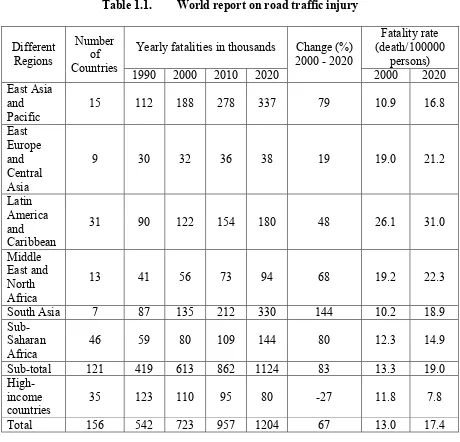
The following table, Table 1.1, is from the World Health Organization on road
traffic injury [4]. It predicts the road traffic fatalities by region (in thousands), and the
data is displayed according to the regional classifications of the World Bank. In this table,
high income countries include North America (USA and Canada), Western and Central
Table 1.1. World report on road traffic injury Different Regions Number of Countries
Yearly fatalities in thousands Change (%) 2000 - 2020
Fatality rate (death/100000
persons) 1990 2000 2010 2020 2000 2020 East Asia
and Pacific
15 112 188 278 337 79 10.9 16.8
East Europe and Central Asia
9 30 32 36 38 19 19.0 21.2
Latin America and Caribbean
31 90 122 154 180 48 26.1 31.0
Middle East and North Africa
13 41 56 73 94 68 19.2 22.3
South Asia 7 87 135 212 330 144 10.2 18.9
Sub-Saharan Africa
46 59 80 109 144 80 12.3 14.9
Sub-total 121 419 613 862 1124 83 13.3 19.0
High-income countries
35 123 110 95 80 -27 11.8 7.8
Total 156 542 723 957 1204 67 13.0 17.4
Market research firm Strategy Analytics predicts that over the period 2006 to
2011, the use of long-range distance warning systems in cars could increase by more than
65 percent annually, with demand reaching 3 million units in 2011, with 2.3 million of
them using radar sensors. By 2014, 7 percent of all new cars will include a distance
"Radar technology is the key to building innovative driver assistance systems to
help avoid automobile accidents," says Hans Adlkofer, Vice President and General
Manager of Infineon Technologies Sense and Control business unit.
Despite the fact that the technology first appeared on luxury cars, crash
prevention systems have started to trickle down to more reasonably priced vehicles. This
will increase the market for telematics and create a positive competition between the
automakers. Global auto industries and governments are extensively pursuing radar based
proximity detection systems such as:
1. ACC support with Stop & Go functionality
2. Pre-crash warning using tri-mode radar system
3. Blind spot detection
4. Self-parking aid
5. Side sensors for parking aid
6. Lane change assistant for the driver
7. Backup camera and sensor for impact warning
8. Car to computer communication devises which utilize GPS tracking feature
9. Geofencing car capability for vehicle tracking
10.Remote speed sensing
The European Commission (EC) had set an ambitious target to reduce road deaths
by 50% by the end of 2010. It has been concluded that the use of Forward Collision
Warning long range radar and Lane Departure Warning camera-based sensor, among
other security features, will become very effective to reduce road fatality rates. In [6], it
vehicles, the number of crashes can be reduced by 3.8 million in North America alone,
and the number of human lives saved from that amounts close to 17,000 per year. This
warrants the use of multi-range radar as an indispensable feature to improve highway
safety and minimize loss of lives and property damage.
1.2 Automotive radar
The first patent of radar application on car was claimed by Christian Huelsmeyer
in a German Patent on 30, April 1904 [7]. Since this time many different radar systems
have been developed for various industries. The general requirement for automotive
radars is to detect any targets in the field of view with high probability, high accuracy and
low false alarm rate. Automotive sensors usually operate in the dedicated frequency band
of 77 GHz. Beside this technology, SRR sensors are under development today in the 24
GHz ISM band.
High performance automotive radars measure target range, azimuth and radial
velocity simultaneously in a short time and have the ability to resolve reflectors in
multiple target situations. The main technical challenge lies in the waveform, antenna and
signal processing design.
1.2.1 Electronically scanned radar
Electronically scanned antenna arrays propose great benefits that facilitate radar
sensors and broadband communications for different military and commercial
applications. The most advanced function of electronically scanned antenna is the phased
antenna array. It implements a large number of individual antenna elements that are
steered by adjusting the amplitude and phase of the RF signal at each of the individual
antenna elements. In other words traditional phased array antennas are constructed with
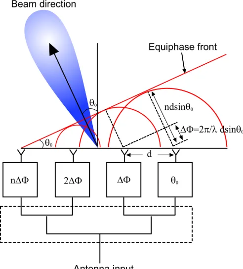
active electronics behind every radiating element. A linear phased array with equal
spaced elements is easiest to analyze and forms the basis for most array designs. Figure
1.1 schematically illustrates a corporate feed linear array with element spacing d. By
controlling the phase and amplitude of excitation to each element, as depicted, we can
control the direction and shape of the beam radiated by the array. The phase excitation,
Φ(n), controls the beam pointing angle, θ0, in a phased array. To produce a broadside beam, θ0 = 0, requires phase excitation, Φ<(n), = 0. Other scan angles require an excitation, Φ(n) = nkd sin(θ0), for the nth element where k is the wave number (2).
The electronics typically includes a phase shifter for setting the beam position and
amplification to overcome the losses of the phase shifter and establish output power or
noise figure of the system. The cost of this microwave electronics circuitry is typically
quite expensive, on the order of $1K - $2K for each antenna element, making
electronically scanned antennas very expensive to build [8] [9].
A way to lower the cost of these radars is to utilize microelectromechanical
systems, or MEMS, approach where we can fabricate our design on low cost material and
eliminate any electronic devices for phase shifting. The Rotman lens offers a cheap and
compact means to extend the single beam systems generally used, to fully functional
beamsteering arrangements. Furthermore the antennae array presented herein radiates the
signal to a specific controlled direction.
The use of MEMS technology to reduce the number of electronics modules
greatly reduces the hardware costs of the radar. In addition, the use of innovative
manufacturing methods allows not only the Rotman lens phase shifter replacement, but
whole antenna arrays to be integrated onto a single substrate. This greatly reducing the
packaging and interconnect complexity, and lowers costs. These two factors make an
inexpensive development of the antenna arrays for both space-based and ground-based
microwave systems. A block diagram for this radar architecture is shown in the next
section.
1.2.2 The MEMS radar
Depending on the range coverage, the radar antenna’s radiation pattern must have
narrow beamwidth of a few degrees, low side lobe levels and high radiation efficiency to
automotive radar antennas on a low cost micromachined silicon substrate is under
development. A MEMS single-pole-Single-Throw (SPST) switch is implemented on the
microstrip antenna array for use in 77 GHz tri-mode automotive collision avoidance
radar. The advantage of such design is that it enables simple integration of the antenna
arrays in the vehicle. Extensive work has been published in the design of planar patch
antenna arrays for automotive radar applications at 77 GHz and serves as a starting point
for this thesis. However, to be able to accomplish higher precision and accuracy, the
usage of a micromachined technology is desirable.
In order to produce a complete sensor or communication device the
implementation of the antenna is a critical aspect. While long distance radar needs large
high gain antennas, the targeted application for this thesis will be tri-mode automotive
collision avoidance radar. At millimetre wave frequency, the use of mechanical scanning
antenna experiences slow response and suffers reliability problem due to shock and
vibration. As for antennas with phase shifters, they are expensive to fabricate and initiate
considerable RF losses. By avoiding those disadvantages, Rotman lens antenna could
open new applications for millimetre wave radar.
The automotive radar module is prepared according to the desired coverage. Long
range radar (LRR), medium range radar (MRR) and short range radar (SRR) are used in
cruise control and collision avoidance applications. Generally, the requirement for
automotive radars is to detect any targets in the field of view with high probability, high
accuracy and low false alarm rate. Automotive radars usually operate in the dedicated
frequency band of 76 – 77 GHz. Beside this technology, today MRR and SRR
laser sensors and video cameras but still provide the advantages of microwave based
sensing with respect to
High performance automotive radars cover different target ranges, measure
azimuth and radial velocity simultaneously in a short time and have the capability to
resolve reflectors in multiple target situations. The main technical challenge lies in the
waveform, antenna and signal processing design.
Having established that automotive radar can be very helpful in reducing the
number of fatal accidents, it is essential that low cost and reliable radar systems be made
to improve road safety globally. Lower cost (compared to $2000-$3000 approx. for
current systems) will enable lower-end vehicles to be equipped with safety options.
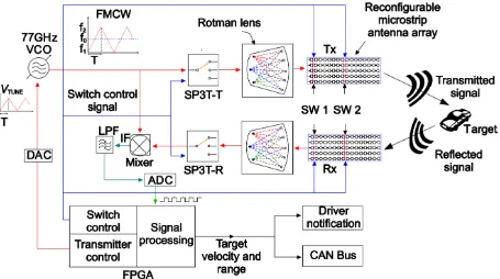
The principle of operation is explained thoroughly in the coming section. The
following block diagram, Figure 1.2, presents the major components of the automotive
The major components of the MEMS based tri-mode radar:
Microfabricated Rotman lens
MEMS SP3T RF switches
TLC MINT77TR GaAs transceiver
MEMS reconfigurable microstrip antenna array
MEMS SPST RF switches
FPGA/ASIC implemented controller
The following figure, Figure 1.3, demonstrates the tri-mode radar coverage currently
under development.
Figure 1.3. Tri-mode automotive radar
1.2.3 MEMS radar principle of operation
Transmitting side:
1. AN FPGA/ASIC implemented control algorithm will generate a linear
frequency modulated continuous wave (LFMCW) signal that will be fed to
a MEMS SP3T switch.
2. The FPGA/ASIC implemented control algorithm controls the MEMS
switch to sequentially trigger the LFMCW signals among the three
4. The signal will travel through the Rotman lens, and the time delayed
in-phase signals are fed to a microstrip antenna array that radiates the signal
in a specific direction.
5. The steering of the radiated signal is guided by the switching of the input
signal among the beamports of the Rotman lens.
6. An FPGA/ASIC implemented algorithm controls the operation of the
MEMS SPST switches to dynamically adjust the microstrip antenna array
from one mode to another.
Receiving side:
7. The microstrip antenna array receives the radiated signal reflected off a
vehicle or an obstacle and feeds the signal to SP3T switch through Rotman
lens.
8. The receiver SP3T switch passes the signal coming to the mixer in order
to generate an IF signal in the range of 0-200 KHz.
9. The analog signal converts to digital through ADC.
10. The received digital signal will be processed by the FPGA/ASIC
implemented algorithm to determine the position of the detected object.
1.3 Research hypothesis
The objective of this research is to develop a 77 GHz reconfigurable
micromachined microstrip antenna array for the aforementioned MEMS based radar
system. The system complexity will be greatly reduced by introducing the MEMS
technology to realize a directional scanning beam without any microelectronic signal
micro-fabrication technology to lower production costs. As a result, the highway safety
situation will drastically improve resulting in less collision, less loss of lives and less
property damage, and will have a significant impact on car insurance premiums.
The micromachined silicon based microstrip antenna array outperforms
conventional Duroid 5880 substrate based microstrip antenna system operating in 77
GHz in terms of low loss, very high efficiency, bandwidth, and low cost batch fabrication
capability for similar design specifications [10]. As the frequency modulated continuous
wave (FMCW) radar requires a high chirp bandwidth to improve the range and velocity
accuracy and resolution, the high bandwidth and high efficiency feature of the designed
antenna array enable to realize high performance tri-mode radar for automotive collision
avoidance applications.
1.4 Motivation
Automotive radar systems in the 77 GHz domain were introduced in the 90’s into
the passenger car market as a security and safety system for the driver [11]. For collision
avoidance applications different ranges are used, having limited potential to extend the
functionality to other applications like stop & go support of narrow beam long range
radar.
For this reason radar systems in the 77 GHz frequency domain, which have good
performance in range and azimuth angle coverage, are of interest and can therefore be
applied in different automotive applications as follows:
Parking Assist with higher precision, longer range and higher update rates than
conventional ultrasonic systems
It provides support to Adaptive Cruise Control systems (ACC) in Cut-in and
Stop & Go-situations due to the fact that the short range sensors can have a
wider beamwidth than the directive long range sensor
Pre-Crash Detection with very high detection update rates
This thesis aims to develop the 77 GHz reconfigurable micromachined microstrip
antenna array for a MEMS based radar system to detect the distance and velocity of
target vehicle(s) in a pre-specified range to meet the requirements of long range radar.
1.5 Principal Results
A micromachined silicon based MEMS single-pole-Single-Throw (SPST) switch
embedded reconfigurable microstrip antenna array for use in a 77 GHz tri-mode
automotive collision avoidance radar is presented. An FPGA / ASIC implemented
algorithm controls the operation of the MEMS SPST switches to dynamically alter the
beamwidth of the antenna array to cycle the radar constantly from short-range (SRR) to
mid-range (MRR) to long range (LRR) mode. Major achieved designed simulation results
of the developed system are listed below:
Table 1.2. Radar simulation results
Parameters SRR MRR LRR
Gain 8.8 dBi 12 dBi 20.5 dBi Azimuth angle 0° 0° 0° Elevation angle 10° 10° 10° -3dB Beamwidth (HPBW) 40° 26° 11° S11 Parameter (return loss) -25.5 dB -25.3 dB -23 dB Bandwidth 1.2 GHz 1.2 GHz 1.8 GHz Radiation Efficiency 97 % 94 % 90 %
Wet etching and wafer bonding based fabrication techniques have been developed
to fabricate the antenna array. The antenna is now in fabrication stage and a working unit
ready for testing will be obtained soon.
1.6 Thesis Organization
Chapter 1 highlights the importance of the work and its outcomes to the present
day. It reviews the significance of radar technology and studies their purpose in the
automotive industry. This chapter recaps the statistics of the World Health Organization
and the vehicle fatality rate in different regions.
Chapter 2 briefly summarizes the existing literature of radar antenna array
technologies and studies their applications in the automotive industry. This chapter
provides a good background and targeted specifications for the MEMS base radar.
Chapter 3 presents all the necessary characteristics and the mathematical concept
of the microstrip antenna array. It includes all the essential parameters needed to design a
microstrip antenna. Also, this chapter details the theory behind antenna arrays and the
difference between linear and planar antenna arrays.
Chapter 4 follows Chapter 3 in introducing and explaining the micromachining
technology and its affect on microstrip antennas. As well, a deep description of various
types of micromachining and how can it manipulate our design in a positive way.
Chapter 5 provides simulation and measurement results of our short range radar
(SRR), mid-range radar (MRR), and long range radar (LRR). In this chapter, an
explanation of the fabrication process is been offered for our antenna.
Chapter 6 concludes this thesis with a summary of our work and what can be done
CHAPTER II
REVIEW OF LITERATURE
This chapter reviews the state-of-the-art in the automotive radar systems and the
antenna arrays used in the automotive radars. The development of MEMS base tri-mode
radar is also discussed. MEMS base radars are then compared to existing radar
technology.
2.1 Literature Review
Worldwide, about 1.2 million people are killed and 50 million people are injured
in road crashes each year [4]. Developing countries are experiencing high rates of
increase in car ownership, population and in demands for enhanced mobility. The
resultant increase in the number of people killed or injured in road crashes poses a great
challenge for those responsible for the road transport system in the developing world. To
enhance road safety system and reduce automobile collisions, automakers and
governments are extensively pursuing radar based proximity detection systems in all
on-road vehicles. As mentioned in the previous chapter that study of crash avoidance
technologies shows a promising potential for reducing road crashes. This technology will
provide safety benefits for motor carriers and all road users.
More than one-quarter of the nearly 400,000 police-reported crashes each year are
potentially relevant to at least one of four crash avoidance technologies: side view assist,
forward collision warning/mitigation, lane departure warning/prevention, or vehicle
stability control. Side view assist has the greatest potential to prevent or mitigate crashes
of the 384,000 police-reported crashes each year. These crashes involve vehicles
traveling in the same direction, and relatively few involve moderate-to-serious injury or
fatality. Vehicle stability control is another promising technology, with the potential to
prevent or mitigate up to 31,000 crashes each year including more serious crashes — up
to 7,000 moderate-to serious injury crashes and 439 fatal crashes per year. Vehicle
stability control could prevent or mitigate up to 20 and 11 percent of moderate-to-serious
injury crashes and fatal crashes, respectively [12].
Accordingly, the National Highway Traffic Safety Administration (NHTSA)
evaluated its Federal Motor Carrier Safety Administration (FMCSA) and computed the
benefits and costs specific to both small and large motor carriers. The evaluation covered
the life-saving benefits as well as the consumer cost for a substantial "core" group of
safety technologies for passenger cars and LTVs (pickup trucks, sport utility vehicles and
vans). In 2002, these technologies added an estimated $11,353,000,000 to the cost of new
cars and LTVs of that model year. They saved an estimated 20,851 lives in the cars and
LTVs on the road during that calendar year. That amounts to $544,482 per life saved in
2002. These technologies added a total of $189,842,000,000 to the consumer cost of new
cars and LTVs over model years 1968-2002. They saved 252,989 lives in model year
1968 and later vehicles during calendar years 1968-2002. That amounts to $750,782 (in
2002 Dollars) per life saved in 1968-2002 [13].
As a solution, the strategic Automotive Radar frequency Allocation (SARA)
consortium allocated 77-79 GHz frequency range for automotive to reduce size and
avoidance technologies, automakers and suppliers are being pursued vigorously to
minimize the cost and size while improving the performance of automotive radars. They
are looking into ways to reduce application cost and batch fabrication capability of the
MEMS technology to implement better sophisticated radar system that can provide
improved performance over the microelectronic conventional based radars.
2.1.1 MEMS technology
MEMS field progressed rapidly from the integrated circuit industry. The most
fundamental characteristics are miniaturization, microelectronics integration and precise
mass production. MEMS technology makes it possible to fabricate electromechanical
and microelectronics component in a single small device ranging from 1 µm ~ 1 cm. The
reduction in dimension of electromechanical systems offers advantages such as soft
spring, high resonance frequency and low thermal mass, and leads to dramatic decrease
in power consumption [15]. In MEMS, while the electronics are fabricated adopting
integrated circuit (IC) process sequences, the micromechanical components are fabricated
using compatible "micromachining" processes that selectively etch away parts of the
silicon wafer or add new structural layers to form the mechanical and electromechanical
devices. The mechanical sensor and actuators with electronic processors and controllers
can be fabricated in a single substrate in an unbroken, wafer-level process flow and
integrated in chip level. The accurate dimension and placement precision is guaranteed
by lithography. The batch-based fabrication process has the potential to scale up in large
2.1.2 Radar type
Car manufacturers and suppliers main objective is to develop a comfort and safety
systems to the driver. Driver assistance and active safety systems are becoming very
important topics in this industry. They help recognize dangerous situations at early stages
and thus facilitate to avoid accidents or at least reduce the accident severity.
Earlier automotive radar systems used pulsed-echo technology that requires high
power pulses and false target detection was a crucial problem for those radars. The
German government (BMBF) funded joint project “Automotive High Frequency
Electronics KOKON” [17] [18] was initiated mainly due to the short range radar (SRR)
frequency regulation in Europe. It has been established that phased array based frequency
modulated continuous wave (FMCW) radars with beamforming and beamsteering
capability is the technology of choice for forward ranging applications. The key
advantages of FMCW based phased array radars are:
1. Low power rating
2. beamsteering capabilities without any mechanically rotating mounting base
3. Low effects of phase noise
4. Decreases the effect of clutter and atmospheric noise
5. High precision target range
6. More resistance to interference from other similar radars in the vicinity
7. Determine velocity of the selected target
8. No theoretical blind spot
Various radars have been designed using different technologies; however, MEMS
Rotman lenses at a time with high precision and low cost while maintaining a tight
tolerance. Rotman lenses can pave the way to realize high performance low cost radar
sensors for automotive collision avoidance application. Moreover, the lens can be
fabricated with silicon based antenna array, FMCW routing MEMS based RF switches,
and it would be possible to realize complete radar in a chip using low cost silicon
technology. The antenna array in this thesis transmits and receives the signals travel
through the Rotman lens that radiates the signal in a specific direction.
2.2 Microelectronic beamforming with phased array antenna
A beamformer is a signal processing technique used in conjunction with an array
of sensors to provide a versatile form of spatial filtering. The sensor array collects spatial
samples of propagating wave fields, which are processed by the beamformer [19]. In
another word, it can direct the transmitted or received signal from an antennae array to a
chosen angular direction to realize spatial selectivity. When transmitting, a beamformer
controls the phase and relative amplitude of the signal at each transmitter, in order to
create a pattern of constructive and destructive interference in the wavefront. When
receiving, information from different sensors is combined in a way where the expected
pattern of radiation is preferentially observed.
In communications, high directivity is desired in the direction of the signal source
for a low-noise high-fidelity link to be established. In radar systems, beamforming allows
a means of electronic steering of a narrow scanning beam to detect targets with higher
Beamformers provide an effective and versatile means of spatial filtering. The
following table, Table 2.1, lists number of applications of spatial filtering, gives examples
of arrays and beamformers, and provides a few key references.
Table 2.1. Applications that employ beamforming
Application Description and References
Radar
Phased array radar [20]; air traffic control [21]; synthetic aperture radar [22]
SONAR Source localization and classification [23] [24]
Communications
Directional transmission and reception [25] [26]; sector broadcast in satellite communications [27]
Imaging Ultrasonic [28]; optical [29]; tomography [30]
Geophysical Exploration Earth crust mapping; oil exploration [31]
Astrophysical Exploration
High resolution imaging of the universe[32] [33]
Biomedical
Fatal heart monitoring [34]; tissue hyperthermia [35]; hearing aids [36]
2.2.1 Microelectronic beamforming types
Beamforming involves both the generation of a directional pattern as well as
steering of the main lobe over the azimuth and also the elevation angles and it can be
categorized into two main types:
a) Analog beamforming
Analog beamforming means that the received signals from each element for the phased
array antenna are combined at the carrier frequency level. Both the amplitude and phase
control can be used to adjust side lobe levels and steer nulls better than can be achieved
by phase control alone [37]. The following figure, Figure 2.1, represents an analog
beamformer using analog RF circuit components:
In a beamforming network typically the signals incident at the individual elements are
combined intelligently to form a single desired beamformed output. Before the incoming
signals are formed, they are brought down to baseband or intermediate frequencies (IF’s).
The receivers provided at the output of each element perform the necessary frequency down
conversion. Therefore it is required that the down-converted signal be converted into digital
format before they are processed. Analog-to-digital converters (ADC’s) are provided for this
purpose. For accurate performance, they are required to provide accurate translation of the
RF signal from the analog to the digital domain.
Various manufacturers used the analog beamforming technology on 77 GHz
frequency for long range radars (LRR) such as Bosch, Delphi, Denso, TRW, Fujitsu Ten,
and Hitachi. Other companies (Delphi, Fujitsu Ten, Mitsubishi electric, Celsius Tech)
used mechanical mechanisms in conjunction with ADC to steer the beam in azimuth [11].
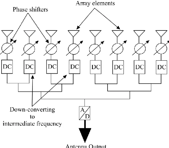
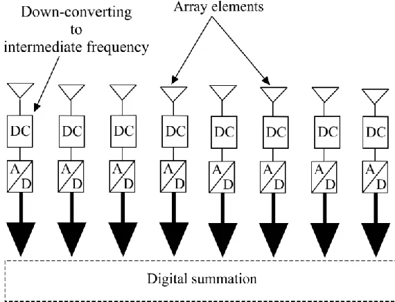
b) Digital beamforming
In digital Beamforming, the operations of phase-shifting and amplitude scaling
for each antenna element, and summation for receiving, are done digitally. Multiple
independent beams steered in all directions can be formed in the digital beamforming
processor. The benefits of this type include:
Improved dynamic range Controlling of multiple beams
Better and faster control of amplitude and phase
Although the digital beamformer will require memory blocks, adders and
multipliers as system building blocks to function, it is still more flexible and efficient
than the analog beamformer [38]. The following figure, Figure 2.2, illustrate a digital
In digital beamforming there are many digital receivers that can be used.
Converting to an intermediate frequency and digitizing the signal is realized at each
individual antenna element.
In 2003, 77 GHz radar sensors with digital beamforming (DBF) front ends were
introduced into the market by Japanese companies. Denso built a bistatic LRR with
planar patch antennas with a range capability up to 150m and a field of view of approx.
±10 degrees [39].
2.2.2 Rotman lens beamforming
Rotman lens offers an inexpensive and compact solution to extend the single
beam systems to fully functional beam staring arrangements. The flexibility of microstrip
transmission lines and the advent of fast accurate simulation packages allow practical
Rotman lenses to be designed at mm-wavelengths. It offers beamforming and
beamsteering capabilities without any microelectronic signal processing as needed in
analog and digital beamformers [40].
It consists of three major components: A semi-circular shaped focal arc that traces
the contour of the beam ports, a curved line called the inner contour that traces the
contour of the array ports, and a straight line known as the outer contour that depicts the
position of the radiating elements. The semi-circular focal arc is sometimes modified
slightly to be elliptical to reduce the aberration [41]. Figure 2.3 shows the general
Typical Rotman lenses are realized using microstrip substrates like Duroid 5880.
The above Rotman lens figure, illustrates the schematic representation of the Rotman lens
designed at the University of Windsor. It was made on a high resistivity Silicon wafer
and it incorporates three input signals and 5 output ports. The central beam guides the
input signal through channels of equal length to the array elements, creating a
forward-facing beam.
On beam ports 1 and 3 the input signal travels through different path lengths to
the antenna patches, thus undergoing phase shift leading to the beam being steered as
shown in the following figure.
2.2.2.1 Antenna array
Antenna arrays with reconfigurable capabilities are of tremendous importance in
many applications, such as satellite communications, radar systems, point to point
communication links and imaging. Planar antenna arrays can satisfy stringent
requirements in terms of low-profile, low-weight and fast beam steering capability. Such
antennas can be controlled in several manners: the use of electronic phase-shifters and/or
amplitude tuners allows one to fully reconfigure the radiation pattern, steer and shape the
beam, introduce nulls and control the side-lobe level. Another method of making a
reconfigurable antenna arrays can be controlled with switches. Modern approach to a
conventional technique is introduced for the electronic control of microstrip patch
antenna arrays. The control is achieved by placing microelectromechanical switches
(MEMS) at appropriate locations in a patch antenna array. The microwave MEMS are
used to switch between open and short circuit conditions that allow reconfiguration of the
modal fields. Changing the number of the patches, changes the radiated field and the area
of coverage. This can be achieved without changing the frequency of operation, input
impedance or radiation pattern of the patch antenna array.
Rotman lens and microstrip antenna array combine the advantages of the low cost
fabrication in printed technology and the low loss characteristics typical of waveguide
devices. This is especially true when low permittivity and high thickness substrates are
employed.
Figure 2.5, presents Rotman lens along with the micromachined microstrip
antenna array:
The above figure illustrates the antenna arrays designed to work with Rotman lens
along with the MEMS RF switches implemented to change the angular coverage of the
radiation pattern. Whether the MEMS RF switched “on” (short circuit) or “off” (open
circuit), the radiation of the antenna arrays changes accordingly.
The reconfigurable antenna arrays and the MEMS RF switches combination
central to this thesis can be used in conjunction with the Rotman lens in order to
accomplish SRR, MRR and LRR beamforming using the same hardware. The control of
such a system would be easily realizable digitally by means of the FPGA control
algorithm.
2.3 State-of-the-art automotive radar
Automotive radar was first experimented in the late 50’s and intensively in the
70’s started at microwave frequencies. The activities of the last decades were
concentrated mainly on developments at 17 GHz, 24 GHz, 35 GHz, 49 GHz, 60 GHz,
and 77 GHz. Even from the early beginning in automotive radar the key driver of all
these investigations has been the idea of collision avoidance; this idea has spent
enormous motivation for many engineers all over the world to develop smart vehicular
radar units [11].
Parking assist, collision warning, and Adaptive Cruise Control (ACC) were the
first applications with surround sensing technologies. In the 90’s, the collision warning
systems were successfully introduced in the US. Greyhound installed more than 1600
radar systems (24 GHz) in their bus lines yielding a reduction of accidents of 21 percent
in 1993 compared to the year before. In 1999, Mercedes introduced the 77 GHz
“Distronic” into the S class, followed by other premium models equipped optionally with
an ACC, such as BMW 7 series, Jaguar (XKR, XK6), Cadillac (STS, XLR), Audi A8,
and VW Phaeton. ACC is also available in Mercedes E, CL, CLK, SL class, BMW 5 and
6 series, Audi A6, Nissan (Cima, Primera), Toyota (Harrier, Celsior), Lexus (LS, GS),
and Honda (Accord, Inspire, Odyssey). Furthermore, ACC will become an option in the
Quite a few standards have been established for different applications. For example,
short-range (m) radars are adopted to provide parking assistance or to prevent side crash.
Because of the short distance, it must provide a wide angular coverage and a good
resolution [42]. The mid-range radars usually operate at 24 GHz band to cover a distance
of 10 – 40 meters with an angle of 30 – 60 degrees [43] [44]. As for long range radars,
the use of 77 GHz band has been dedicated for such coverage, which basically detects the
distance and the relative speed of the vehicles in front so as to perform a real-time
response by means of the braking system or other protective mechanism. It must cover a
range up to 100 – 150 meters [11]. Table 2.2 represents the general standard of
automotive radar.
Table 2.2. Classifications of automotive radar systems
Radar
type Frequency BW Angle Range Resolution Application
SRR 24 GHz 7 GHz 70° 10m <10cm Side crash parking MRR 24 GHz 250 MHz 30~60° 40m ~ 1m Stop & go
LRR 77 GHz 1 GHz 16° 150m ~ 1m ACC
Various car manufacturers and suppliers are developing optimized sensor
configurations for comfort and safety functions with respect to functionality, robustness,
reliability. Last but not least the total system costs have to meet the marketing targets to
be attractive for the end users. The following table, Table 2.3, provides one of the biggest
Table 2.3. New generation of automotive radar systems [11]
Company Frequency Radar type
Range of coverage
Relative velocity (km/h)2
Field of view
TRW 77GHz LRR 1 – 250 m ±220 ±8° Delphi 76.5 GHz LRR 1 – 174 m -360 to +90 ±10°
Denso 77 GHz LRR 2 – 250 m ±200 ±20° Chrysler 76 ~ 77 GHz LRR 1 – 200 m -100 to +260 ±20° Bosch 77 GHz LRR 0.5 – 250 m -500 to +250 ±30°
From the above table, Bosch radar system is one of the most recent released
applications. It was launched in 2009 on the Porsche Panamera 2010 model. Bosch
claims to have the world's smallest radar sensor package at 74mm x 77mm x 58mm.
Another radar system The MEMS radar system being developed at the University of
Windsor has close to half the dimensions at 30mm x 40mm x 10mm owing to the
compact MEMS Rotman lens beamformer and antenna design.
2.4 State-of-the-art antenna array
This section provides an overview of the state of the art of smart antennas, and is
particular focused on the reconfigurable antennas as the most quickly developing devices
in recent years.
Considering all aspects of the designing process of antenna arrays it can be quite
demanding, but it also provides an excellent opportunity to combine state-of-the-art
technologies with the antenna theory in an attempt to provide additional degrees of
freedom in system performance [10]. Antenna array comes in large variety of different
shapes and forms. These types of antennas are typically described by some categories,
frequency and/or bandwidth. The following table, Table 2.4, provides different antenna
array designs close to our design requirement:
Table 2.4. Different antenna array designs
Year Frequency Radar Antenna Azimuth Gain BW
2005 [45] 76.5 GHz SRR Microstrip (4x12) Rectangular ±25.5° 17.8 dBi 1.0 GHz
2005 [45] 76.5 GHz SRR Microstrip (2x12) Rectangular ±39.3° 15.5 dBi 1.0 GHz
2010 [46] 34.5 GHz SRR Rectangular
Microstrip (1x1) 60° 9.0 dBi 1.2 GHz 2005 [47] 122 GHz SRR Rectangular
Microstrip (1x1) 90° 3.2 dBi 2.0 GHz 2004 [48] 24 GHz MRR Microstrip (4x6) Rectangular ±12° N/P 500 MHz
2008 [49] 140 GHz LRR Microstrip (2x4) Rectangular 20° 12 dBi 2.0 GHz
2010 [50] 77 GHz LRR Microstrip (8x8) Rectangular ±9° 20 dBi 1.0 GHz
The state-of-the-art of the automotive radar systems and the antenna arrays
provide the objective for this thesis and help set the goal for efficiency and performance
CHAPTER III
MICROSTRIP PATCH ANTENNA
This chapter presents the state-of-the-art literature reviews on microstrip antenna,
including basic theory, analysis, and feeding methods that are essential for the target
antenna array design. As the target microstrip antenna array will have a planar
configuration for use in conjunction with the Rotman lens, a review of planar antenna
theory is also presented.
3.1 Microstrip patch antenna
Microstrip Patch antenna has been a common choice for integrated antennas not
only for automotive but also for various other industries. Government, military, and
medical sectors are leading the majority of research initiatives for the development and
deployment of wearable communication systems. As populations grow and age, the
demand on health care resources increases and many governments are looking for remote
healthcare solutions. Military applications are focused on integrating these devices into
military clothing in an attempt to enhance soldier performance, awareness and
survivability on the battle field. Due to their simple design, planar configuration, high
gain, and low fabrication cost [52], microstrip patch antennas are becoming the
technology of choice for such applications.
A microstrip patch operates like a resonant cavity, where the patch forms the top
of the cavity, the ground plane is the bottom of the cavity, and the edges of the patch
form the sides of the cavity. The edges of the patch act as an open-circuit boundary
condition. Hence, the patch acts approximately as a cavity with perfect electric conductor
good antenna performance, a thick dielectric substrate having a low dielectric constant is
desirable since this provides better efficiency, larger bandwidth and better radiation [15].
However, such a configuration leads to a larger antenna size.
The metallic patch may be of various geometries, with rectangular and circular
being the most common used shapes. The patch is generally made of conducting
materials such as gold or copper. The radiating patch and the feed lines are usually etched
out of a metal deposited on the top of a dielectric substrate. Figures 3.1 and 3.2, shows
the standard microstrip structure in three different views:
The microstrip patch geometry is commonly square, rectangular, circular,
triangular, and elliptical or some other common shapes as shown in the Figure 3.3. For
the target application we have chosen to work with rectangular patches since it has the
largest impedance bandwidth compared to other types of geometries.
Figure 3.3. Microstrip patch antenna geometry
3.2 basic Principle of Operation
Microstrip patch antennas radiate because of the fringing fields between the patch
edge and the ground plane. There are many methods to analyze a microstrip patch
antenna and the most popular models are the transmission line model, cavity model, and
full wave model. The transmission line model is the simplest and it gives good physical
insight but it is less accurate [53]. The cavity model is more accurate and gives good
physical insight but is complex in nature. As for the full wave model, it is extremely
accurate, versatile, and can treat single elements, finite and infinite arrays, stacked
elements, arbitrary shaped elements, and element coupling. These give better insight as
compared to the two models mentioned above and are far more complex in nature [10]. In
this thesis, the transmission line model has been used to determine initial design
specifications which are then optimized using a full wave analysis using a finite
difference time domain (FDTD) method.
3.2.1 Transmission line model
The transmission line model represents the microstrip antenna by two slots of
width (W)and height (h), separated by a transmission line of length (L). The microstrip is
essentially a non-homogeneous line of two dielectrics, typically the substrate and air.
Hence, as seen from Figure 3.4, most of the electric field lines reside in the substrate and
parts of some lines in air. As a result, this transmission line cannot support pure
transverse-electromagnetic (TEM) mode of transmission, since the phase velocities
would be different in the air and the substrate. Instead, the dominant mode of propagation
would be the quasi-TEM mode. Hence, an effective dielectric constant (εreff) must be
value of εreff is slightly less than εrbecause the fringing fields around the periphery of the
patch are not confined in the dielectric substrate but are also spread in the air as shown in
Figure 3.4. The expression for εreffis given by Balanis [10] as:
1 / 12 1 2 1 2
1 1/2
h W W h r r reff
3.1where; εreff is the effective dielectric constant
εris the dielectric constant of substrate
h is the height of dielectric substrate
W is the width of the patch
Figure 3.5 shows a rectangular microstrip patch antenna of length (L), width (W)
resting on a substrate of height (h). The co-ordinate axis is selected such that the length is
along the x-axis direction, width is along the y-axis direction and the height is along the
z-axis direction.
In order to operate in the fundamental TM10 mode, the length of the patch must be
slightly less than λ/2 where λ is the wavelength in the dielectric medium and is equal to
λo/√εreffwhere λo is the free space wavelength. The TM10 mode implies that the field varies
one λ/2 cycle along the length, and there is no variation along the width of the patch. In
the Figure 3.6 shown below, the microstrip patch antenna is represented by two slots,
separated by a transmission line of length L and open circuited at both the ends. Along
the width of the patch, the voltage is maximized and the current is minimized due to the
open ends. The fields at the edges can be resolved into normal and tangential components
with respect to the ground plane.