MOHD RIDHWAN BIN RAMLI
A project report submitted in partial fullfilment of the requirements for the award of the degree of
Master of Engineering (Mechanical – Advanced Manufacturing Technology)
Faculty of Mechanical Engineering, Universiti Teknologi Malaysia
To my beloved my wife Zariwani Zakaria, dedicated supervisor Associate Professor Zainal Abidin Ahmad, Tn. Haji Fadhil Ahmad, Tn. Haji Azhar Zubir, and Mr. Helmi
ACKNOWLEDGEMENT
Alhamdullilah, thank to Allah, because of Him we are still here, breathing His air, pleasuring His entire gift in this world. And most of all, for giving me opportunities to learn His knowledge.
This work was supervised by Associates Professor Zainal Abidin Ahmad at the Universiti Teknologi Malaysia. I greatly appreciate all his help and guidance.
I am indebted to lovely wife, Zariwani Zakaria whose help, encouragement and patience I would never have gotten this thesis completed and who made it all worthwhile.
I would also like to thank my friends, Imran Ibrahim, Huzaimi A. Hamid, and Hamzah Mahmood for their support and encouragement and other help throughout. I am also grateful to Tuan Haji Fadhil Ahmad and Tuan Haji Azhar Zubir who also gave me a great deal of support and encouragement.
iii
ABSTRACT
ABSTRAK
v
TABLE OF CONTENTS
CHAPTER TITLE PAGE
DECLARATION ii
DEDICATION iii
ACKNOWLEDGEMENTS iv
ABSTRACT v
ABSTRAK vi
TABLE OF CONTENTS vii
LIST OF TABLES x
LIST OF FIGURES xi
LIST OF ABBREVIATIONS xiii
LIST OF SYMBOLS xiii
LIST OF APPENDICES xiv
1 INTRODUCTION
1.0 Introduction 1
1.1 Objective 4
1.2 Scope of Work 5
2 LITERATURE REVIEW
2.1 Overview of the Previous Data on
Bricks Making Machine 7
2.2 Overview on the Previous Data Regarding
Research on the Interlocking Bricks 16
3 METHODOLOGY
3.0 Introduction 17 3.1 Concept development phase 18
3.1.1 Identifying customer needs 18 3.1.2 Establishing target specifications 18
3.1.3 Concept generation 19
3.1.4 Concept selection 19
3.1.5 Setting final specification 20 3.2 Concept development
3.2.1 Identifying customer needs 21 3.2.2 Establishing target specifications 22
3.2.3 Concept generation 29
3.2.4 Concept selection 39
3.3 Discussion 43
4 RESULT AND DISCUSSION
4.1 Product architecture 46
4.1.1 Detail Design 47
4.1.2 Material and Process Selection 55
4.1.3 Detail Drawing 65
4.2 Components analysis 77
4.2.1 Top Structure 78
vii
4.2.3 Compactor Structure 82
4.2.4 Planar base Structure 84
4.3 Cost analysis 86
4.3.1 Guideline for Calculating Bricks selling Price 86
4.3.2 Machine component and Raw Material Cost 90 4.4 Product design specification 101
5 CONCLUSION 5.1 Introduction 103
5.2 Conclusion 104
5.3 Future Development 105
REFERENCES 108
LIST OF TABLES
TABLE NO. TITLE PAGE
3.1 Customer statement and interpretation 21
3.2 Customer needs 22
3.3 Matrix table 28
3.4 Needs-matrix table 28 3.5 Concept 1 description 35 3.6 Concept 2 description 37 3.7 Concept 3 description 39 3.8 Concept screening matrix 40 3.9 Concept scoring matrix 42 4.1 Material and process selection 55 4.2 Hydraulic function diagram 71
4.3 Material cost 97
4.4 Screw and nuts cost 98
4.5 Mechanical system and equipment cost 99 4.6 Manufacturing cost 100
4.7 Final product design specification 101
5.1 Project 1 schedule 106
ix
LIST OF FIGURES
FIGURE NO. TITLE PAGE
1.1 Type of Interlocking Brick 4 1.2 Flow chart represents the scope of work 6 2.1` Brick making machine by Hans C. Sumpf 8 2.2 Brick making machine by Judson A. Hereford 9 2.3 Brick inverter machine by Nicholas Lyons and C.K. George 10
2.4 Brick making machine by C.D. Vernon 11
2.5 Brick making machine by Lewis Polak 12
2.6 Brick making machine by Donald P. Chennells 13
2.7 Small size bricks making machine 14
2.8 Medium size bricks making machine 15
2.9 Large size bricks making machine 16
3.1 Method of designing the interlocking brick making machine 20
3.2 Cement charging/loading 30
3.3 Operator leveled the cement 30
3.4 Device to turn the brick 30
3.5 Process of turn the brick 31
3.6 Before compaction process 31
3.7 Pressure loading on bricks 32
3.14 Concept 3-Horizontal compaction concept (3D view) 38 3.15 Concept 3-Horizontal compaction concept (Drawing view) 38
4.1 Total assembly design 48
4.2 Mold assembly design 49
4.3 Table structure assembly design 50
4.4 Top structure assembly design 51
4.5 Charging system assembly design 52
4.6 Inside control panel 53
4.7 Electrical Wiring Diagram 66
4.8 PLC Wiring Diagram 67
4.9 Indicator Lamp Wiring diagram 68
4.10 Hydraulic circuit diagram 69
4.11 Top structure stress analysis 78
4.12 Top structure displacement result 79
4.13 Table structure stress analysis 80
4.14 Table structure displacement result 81 4.15 Compactor structure stress analysis 82 4.16 Compactor structure displacement result 83 4.17 Planar Base structure stress analysis 84 4.18 Planar base structure displacement result 85
4.19 Total assembly drawing 92
4.20 Mold assembly 93
4.21 Table assembly drawing 94
4.22 Top structure assembly drawing 95
xi
LIST OF ABBREVIATIONS
CAE - Computer Aided Engineering
CATIA - Computer Aided Three-Dimentional Interactive Application
D - Bore Diameter
DfX - Design for Assembly, Manufacturing, and Environment EDM - Electrical Discharge Machine
Kg - Kilogram
KN - KiloNewton
PDS - Product Design Specification PLC - Programmable Logic Controller
LIST OF SYMBOLS
π - pi (3.1415)
P - Pressure
LIST OF APPENDICES
APPENDIX NO. TITLE PAGE
A-1 Machine assembly drawing 112
A-2 Mold assembly drawing 113
A-3 Table assembly drawing 114
A-4 Top structure assembly drawing 115
A-5 Charging system assembly drawing 116
A-6 Brick pusher drawing 117
A-7 Charger drawing 118
A-8 Compactor drawing 119
A-9 Container drawing 120
A-10 Cover drawing 121
A-11 Hinge drawing 122
A-12 Middle bar drawing 123
A-13 Mold drawing 124
A-14 Movable base drawing 125
A-15 Planar base drawing 126
A-16 Horizontal plate structure drawing 127
A-17 Pusher base drawing 128
A-18 Pusher shaft drawing 129
A-19 Rod drawing 130
A-20 Slider base drawing 131
xiii
A-22 Slider pusher drawing 133
A-23 Structure table 1 drawing 134
A-24 Structure table 2 drawing 135
A-25 Structure base drawing 136
A-26 Table structure drawing 137
A-27 Top mold drawing 138
A-28 Top structure 1 drawing 139
A-29 Top structure 2 drawing 140
B-1 Hydraulic cylinder 141
B-2 Hydraulic power pack 1 142
B-3 Hydraulic power pack 2 143
B-4 Vibration motor 144
C-1 Socket hex cap screw 145
C-2 Bolt, washer and nut 146
C-3 Bearing bush 147
CHAPTER 1
INTRODUCTION
1.0 Introduction
No construction is possible without bricks. Since many centuries brick making has been practiced by human beings. Presently, bricks are easily made by using machines using new technologies. Generally two types of bricks are manufactured by using machines that are concrete block machines and clay brick machines. Different types of automatic machines use different techniques to make bricks. The raw materials used by the machines for making interlocking bricks are fly ash, sand lime, iron oxide, lime sludge, quarry wastes etc.
2
type of production system. It is an effective means of utilizing wastes generated by stone crushers, quarrying and stone processing units. The technology has high potential in areas where raw materials are easily available. The new technique in producing this interlock brick can generate a highly profitable business for micro and small scale building material producers and construction companies. The market for this type of brick in Malaysia is not yet growing at a rapid rate, even though there are demands in construction industries due to low production rate which reflect the cost of brick itself.
1.0.1 Interlocking Brick Specification
Current process of producing the interlocking brick is produced using a semi-mechanized stationary type machine. The other production systems are - manual moulds that require hand tamping, a mobile semi-mechanized egg-laying machine and fully mechanized system that combines compression and manual concrete filling in mould. The machine also compacts and consolidates the mix so that the blocks are uniform in size and attain desired physical properties. The blocks are cured for a minimum period of 14 days, before they are ready to use. On an average 600-800 blocks can be in 8 hours by 1 skilled and 6-8 semi-skilled workers.
In this project, a high quality machines in which optimize from the current machine design is going to propose according to the feedback and the need from the interlocking brick maker.
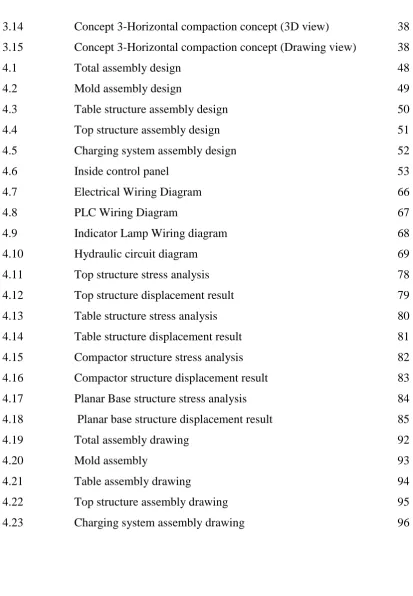
1.0.3 Types of Interlocking Bricks
There are various types of interlocking bricks. The most commonly used cement interlocking bricks are;
i. Regular Shaped Brick ii. Half Size Brick iii. U-Shaped Brick
4
Half Size Brick Regular Shaped Brick
U- Shaped Brick
1.1 Objective
The main objective of this project is to design a new bricks making machine with new features and simplifying the machine for one man operation in order to reduced operational cost and maximizes the production rate. Furthermore, the purpose of this is to design the interlocking bricks making machine that suitable for SME entrepreneurs.
The scope of project is clearly define the specific field of the research and ensure that the entire content of this thesis is confined the scope. This project is start with the literature review on product specification in order to satisfy the project objectives. After obtaining the product specification, this project is done base on the scope below;
Project will focus on interlocking brick making machine only.
Designing the inter-locking brick making machine that fulfill the project
objective.
Machine design to suit the regular interlocking bricks (Figure 1.1).
The project goes until detail design of interlocking brick making machine. The major output of this project is to produce the detail drawing for the machine
design.
Fabrication of machine is excluded in this project.
6
`
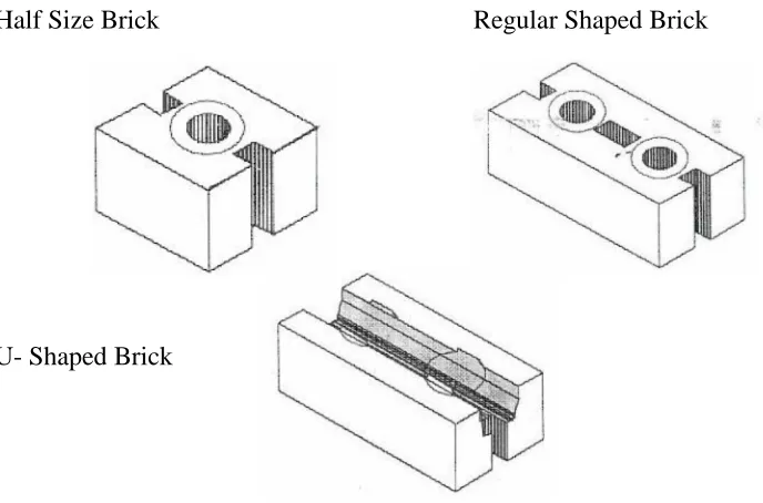
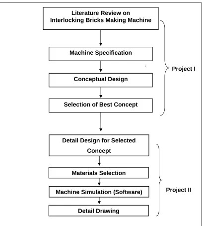
Figure 1.2: Flow chart represents the scope of work
Literature Review on
Interlocking Bricks Making Machine
Machine Specification
Conceptual Design
Selection of Best Concept
Project II Detail Design for Selected
Concept
Design
Materials Selection
Machine Simulation (Software)
Detail Drawing