Design of SC Walls Subjected to Impactive Loading for Local and Global
Demands
Joo Min Kim1, Jakob Bruhl2, Amit Varma3
1
Graduate Student, School of Civil Engineering, Purdue University, West Lafayette, IN 47907, United States
2
U.S Army and Purdue University, School of Civil Engineering, Purdue University, West Lafayette, IN 47907, United States
3
Professor, School of Civil Engineering, Purdue University, West Lafayette, IN 47907, United States
ABSTRACT
Steel-plate composite (SC) walls have been shown experimentally to have excellent resistance to impactive loading, such as from impacts resulting from internally generated missiles, external hurricane borne missiles, or other extreme event missiles. This is a significant advantage for SC walls, and also one of the primary reasons for their increasing use in safety-related nuclear facilities. This paper presents a comprehensive review and evaluation of the missile impact resistance of SC walls. This paper reviews design recommendations to prevent perforation (i.e. local failure) and assessment methodologies to estimate total and global displacement (i.e. global response) of SC walls subject to impact loads. This paper also describes numerical modelling methods to predict local and global behaviour and provides design recommendations for research engineers and design professionals in the nuclear power and protective construction industries.
INTRODUCTION
Steel-plate composite (SC) walls consist of two steel plates, tie bars, stud anchors and concrete. Figure 1 depicts a typical SC wall section. Composite action is provided by studs on the inner surface of each steel plate. Tie bars provide shear reinforcement and stability during construction. The behaviour of SC structures under design basis loads (i.e. flexure, in-plane shear, and out-of-plane shear) has been experimentally studied and design methods compiled into Appendix N9 of AISC N690s1-15: this specification provides strength requirements for proportioning each element of the system.
Figure 1. Typical SC Wall Section (from Johnson et al. (2014))
This paper reviews these current methods to prevent perforation (i.e. local failure) and assessment methodologies to estimate total and global displacement (i.e. global response) of SC structures subjected to impact loads. Numerical modelling methods to assess local and global response including SDOF, TDOF, and finite element (FE) analyses are described. Finally, the paper provides design recommendations for research engineers and design professionals in the nuclear power and protective construction industries.
DESIGN OF SC STRUCTURE AGAINST LOCAL FAILURE
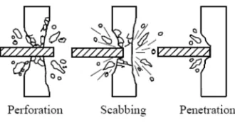
Limit states of reinforced concrete (RC) walls subjected to impactive load can be classified as perforation, scabbing, and penetration (Figure 2). Empirical formula and design methodologies to determine required wall thickness of RC walls to prevent local failure by any limit state are well established and publicly available (NEI 07-13, DOE 3014).
Figure 2. Missile impact failure modes of RC walls (from Hashimoto et al. (2005))
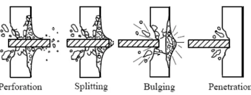
The local failure modes of SC walls subjected to missile impact differ from those for RC walls as shown in Figure 3. SC walls may experience penetration, bulging, splitting and perforation sequentially.
Pipe Sleeve (for Penetrations Through SC Panel)
Steel Headed Stud Anchors Steel Plate
Tie Bars Concrete
Steel Plate Embed Plate
Generally, scabbing is prevented by steel plates and perforation is considered to be the governing local failure mode.
Figure 3. Missile impactive load failure mode of SC walls (from Hashimoto et al. (2005))
Bruhl et al. (2015a) proposed a three-step method to design SC walls to prevent perforation against impactive loading. This three-step approach was validated against a database of 130 test results by different researchers over three decades. The proposed method is applicable to conventional steel and concrete construction materials and can be used for a wide range of missile parameters. The method can account for rigid or deformable missiles with initial missile velocity between 60 ft/sec and 750 ft/sec. Missile diameter can be smaller than or equal to twice the wall thickness and there is no limit on missile weight. Results were compared to three other recommended methods all of which converted steel faceplates to an equivalent concrete thickness (Walter and Wolde (1984), Tsubota (1993), Grisaro and Dancygier (2014)).
Step 1: Select Concrete Wall Thickness
The first step is to select initial concrete wall thickness (TC). TC can be determined based on existing
design, other design requirements or 70% of the RC wall thickness calculated for missile resistance by the modified-NDRC equation.
Step 2: Estimate the Weight and Velocity of Concrete Plug
Using the initial concrete wall thickness, the next step is to compute the weight and residual velocity of the dislodged conical frustum (plug) by the missile after penetrating the SC wall. Effect of the impact side steel faceplate is neglected and a reduction factor for projectile deformability is included.
Step 3: Determine Required Rear Steel Plate Thickness, tpr , to Resist Perforation
Finally, calculate the required thickness (tpr) for the rear steel faceplate to prevent tearing fracture of the rear steel faceplate by the impacting concrete plug projectile and original missile. This required thickness should be used on both faces of the SC wall.
Comparison to Experimental Results
The experimental results were also compared to results of three methods which recommend converting the rear steel faceplate to equivalent concrete thickness. A summary comparison of these methods to the experimental database is shown in Table 1. As seen, the three-step method (“Proposed method” in Table 1) had fewer unconservative results and more conservative results than the other methods considered.
Table 1: Summary comparison of various methods to experimental database (from Bruhl et al. 2015a)
ASSESSMENT OF TOTAL AND GLOBAL RESPONSE OF SC STRUCTURE
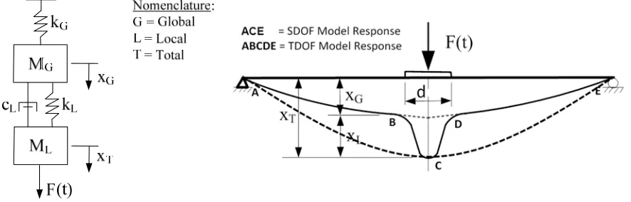
Although an SC wall is designed to resist local failure, it must meet other response limits, such as maximum displacement, flexure, shear, and end rotation. Bruhl et al. (2015b) proposed using a SDOF evaluation to predict the maximum total displacement, xT, of a flat and square SC wall panel. The authors developed an idealized bi-linear resistance function calculated from section properties of the SC wall. The total displacement, xT, can be calculated by numerically solving the equation of motion and this displacement can be compared to clearance limits for internal components with which contact from the wall would be unacceptable. Deformed shape assumptions are shown in Figure 4. As shown, the SDOF model estimates total deformation, xT, which includes contributions from global bending, xG, and localized deformation, xL.
Figure 4. (a) Idealized TDOF System Model and (b) Definition of Local, Global and Total Displacements (from Bruhl et al. (2015c))
The maximum local displacement, xL, is not a particularly useful value to the designer assuming the wall had been designed to resist local failure (perforation). This local deformation is due to formation of a concrete frustum beneath the loaded surface, similar to punching shear failure in RC panels. Importantly, punching shear as a failure mode is inherently prevented by an SC wall designed to resist local failure: the displacement of the frustum leads to highly localized deformations, but the rear steel plate will not rupture.
SDOF Analysis of Total Displacement
SDOF analysis of RC walls can be adapted for SC walls due to their global geometric similarity. The generalized SDOF equation of motion is:
M
·
ݔሷ(t)
+
C
·
ݔሶ(
t
) +
R
(
x) ·
x(
t
) =
F
(
t
)
(1)
M is the effective mass of the structure, C is the effective structural damping, R(x) is the resistance as a function of the displacement x(t), F(t) is the applied forcing function, and ݔሶ
(
t
) and
ݔሷ(t)
are the first and second derivatives of the displacement of the mass with respect to time (the velocity and acceleration, respectively). Typically, the maximum displacement takes place in the first cycle and structural damping, C, can be conservatively neglected. Therefore, Equation (1) can be rewritten as Equation (2) below.M
·
ݔሷ(t)
+
R
(
x) ·
x(
t
) =
F
(
t
)
(2)
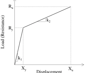
To solve this equation of motion (Equation (2)) and obtain displacement, the desired forcing function, idealized static resistance function (Figure 5) and effective mass for the panel (calculated using tabulated load and mass transformation factors) are required.
Figure 5. Idealized SC Structure Resistance Function (from Bruhl et al., 2015b)
Two parameters were identified which changed the governing failure mode from flexure to shear-dominated. As tie bar reinforcement ratio (
ρ
t) was reduced
and/or tie bar spacing ratio (S
/
t
sc)
increased, the risk of shear failure increased. The slenderness ratio (s/tp) can also affect the governing failure mode and this parameter should be selected in accordance with AISC N690s1 Appendix N9. The resistance function defined above is applicable only for flexure-controlled SC walls which require proper detailing.TDOF Analysis of Global Displacement
SDOF analysis has an inherent limitation - it can only explain maximum total displacement, xT, because it considers the whole wall as a single mass. This is reasonable for certain cases when global bending
Load (R
e
sistan
ce)
Displacement Ry
Xy Xu
Ru
k2
dominates the response. For other cases, diagonal shear cracks around the perimeter of the loaded surface form a concrete frustum leading to localized deformation. The concrete frustum would not be separated from the wall since it is restrained by the front and rear steel plates but would lead to localized yielding of the steel plates. For this situation, more detailed analysis of SC walls can be accomplished by adding an additional degree of freedom which accounts for the effective mass of the concrete frustum and displacement associated with this localized deformation, xL.
Figure 4 shows the idealized TDOF system model and how it differs from the SDOF model. In the idealized TDOF system model, the local effective mass, ML, is considered as the mass of the dislodged concrete frustum estimated from its volume. The global effective mass, MG, is the same mass as for the SDOF model minus the local effective mass.
The resistance functions for the global and local displacements can be extracted from the finite element models from which the SDOF resistance function was developed. From their preliminary work, Bruhl et al. (2015c) demonstrated that idealized bi-linear resistance functions could be applied for both local and global degrees of freedom but did not develop idealized models for these functions. With the resistance functions
the TDOF equilibrium equations (Equations (3) and (4)) can be solved for the local and
global displacements:
M
Gݔሷ
G+ k
Gx
G– k
L(x
T– x
G) – c
L(
ݔሶ
T-
ݔሶ
G)
=
0
(3)
M
Lݔሷ
T+ k
L(x
T– x
G) + c
L(
ݔሶ
T-
ݔሶ
G)
=
F(t)
(4)
where,
k
G andk
L are nonlinear and depend on both load and load path which includes unloadingbehaviour,
x
G is the deformation due to global bending andx
L is local deformation.c
L(
ݔሶ
T-
ݔሶ
G)
is anequivalent damping force. With the central finite difference approximations, the TDOF equilibrium equations can be rewritten as the following recursive equations for the system at time ti:
x
G,i+2= –
[
(
Δ
t)
2/M
G][k
Gx
G,i+1– k
L(x
T,i+1– x
G,i+1)
]
– (x
G,i– 2x
G,i+1)
+ (c
LΔt/M
G)[x
T,i+1– x
T,i– x
G,i+1+ x
G,i]
(5)
x
T,i+2=
[
(
Δ
t)
2/M
L][F
i+1– k
L(x
T,i+1– x
G,i+1)
]
– (x
T,i– 2x
T,i+1)
– (c
LΔt/M
L)[x
T,i+1– x
T,i– x
G,i+1+ x
G,i]
(6)
Both kG and kL have elastic and strain-hardened portions according to the displacement of global and local spring. Damping is only considered for the local degree of freedom. This damping force is included in the equilibrium equations to account for the energy dissipating behaviour of the frustum and slab interface.
FINITE ELEMENT MODEL FOR IMPACT ANALYSIS OF SC WALLS
Numerical models were developed using LS-DYNA to verify local and global behaviour of SC walls. The local behaviour focused on local failure modes (perforation, penetration and bulging). On the other hand, global behaviour focused on estimating the maximum total, local, and global displacements and the end rotation of SC panels. Therefore, it should be noted that two separate, yet related, modelling strategies were adopted for local and global analyses.
Local Assessment
modelled: concrete core, steel faceplates, tie bars and stud anchors. Solid elements were used for concrete and steel faceplates. The Winfrith concrete material model (MAT_084/085) was used with erosion criteria defined to allow separation of the concrete conical frustum. The concrete was modelled in two different mesh densities. The central region in which the conical frustum forms was meshed finely with 0.125 in. solid elements using constant stress reduced integration elements (SOLID ELFORM 1). The outer region consisted of a courser mesh of 0.5 in. solid elements with the same element formulation. The steel plate was modelled with the same mesh density as the concrete. A bilinear kinematic hardening material model (MAT_003) was used for the steel plate, stud anchors and tie bars. Tie bars and studs were modelled using beam elements mathematically embedded in the concrete bulk (assuming perfect bond) and attached to the steel plates using zero-length discrete beam elements to include interfacial force-slip displacement behaviour. For impact analysis, an increase in strength due to high strain rates involved in the deformation process is appropriate and dynamic increase factors were applied as described in NEI 07-13. Penalty based contact definitions were used to account for contact between the missile and SC wall as well as between the steel faceplates and concrete bulk. The missile was assumed as non-deformable and modelled as rigid cylinder (MAT_020). Initial velocity was assigned to the rigid missile and no restraints were applied to its translation or rotation.
Total and Global Assessment
As Bruhl et al. (2015b) described, to develop the resistance functions of SC walls for central concentrated loads, the same finite element modelling strategy of SC walls as for local assessment was used with three major exceptions. First, because the local assessment model was developed to investigate local perforation effects, the mesh size was small. For total and global assessment, the mesh was larger because the focus was on global behaviour rather than local damage. Second, the local assessment model was for dynamic analysis so strain rate effects on material strength were included in the analysis. The global analysis was for quasi-static performance so strain rate effects were not considered. Third, because this was a quasi-static test and local damage was not of primary interest, there was no erosion criteria defined for the concrete elements.
These same models were used to quantify the displacement time-history of SC walls subjected to missile impact which did not perforate the walls. In this case, strain rate effects were included because of the dynamic nature of the loading. These results of maximum displacement compared favourably to predictions using the SDOF model with idealized bi-linear resistance function for cases in which the ratio of missile diameter to span length was the same as the ratio used for the development of the resistance functions.
CONCLUSION AND DESIGN RECOMMENDATIONS
The three major design considerations of impactive loadings on SC walls used in nuclear power plant designs are as follows. First, perforation should be prevented. Second, the maximum displacement of the SC wall should be limited to ensure internal equipment is not damaged. Lastly, end rotations of SC wall should be limited to ensure stability. This paper reviewed current methods to address each of these three design considerations.
A three-step method to design an SC wall to prevent perforation was reviewed. This method was validated against the complete experimental database and compared to other methods which convert the rear steel faceplate to equivalent concrete thickness. The three-step method can be used within its range of applicability to design SC structure to prevent perforation.
displacement with reasonable accuracy. However, for cases in which localized deformation (but not perforation) is expected, it was recommended that the TDOF model be used.
Ensuring ductile flexural behaviour is an important factor in the design of structural elements to resist impact loads. This can be accomplished through general design considerations and specific detailing to improve shear resistance. AISC N690s1-15 Appendix N9 requires that tie bar spacing be no greater than tsc/2 in order to account for the tie bar contribution to the shear strength of the section. Also shear strength
must be at least 25% larger than the flexural strength in order to be classified as a flexure-controlled section.
FUTURE WORK
As described above, current methods suggest two separate models for impact assessment: one focused on local behaviour and a second for global response. A single modelling method to evaluate both local and global behaviour would be useful.
Current methods require an appropriate finite element model in order to obtain resistance functions for the TDOF model. Previous research provided formulas to calculate resistance function and effective mass for SDOF model in lieu of finite element models. Additional research to develop idealized global and local resistance functions for SC walls is necessary.
Additional research of the available ductility of SC walls for different boundary conditions is necessary to define appropriate design limits for structural elements. Current research has demonstrated that ductility of SC walls is at least as large as that of RC walls but additional experimental and analytical research is needed.
REFERENCES
American Institute of Steel Construction. (2015). "Specification for Safety-Related Steel Structures for Nuclear Facilities Including Supplement No. 1." (ANSI/AISC N690s1-15) Chicago, IL: American Institute of Steel Construction.
Bruhl, J. C., Varma, A. H., and Johnson, W. H. (2015a). "Design of composite SC walls to prevent perforation from missile impact." International Journal of Impact Engineering, 75, pp. 75–87. doi: 10.1016/j.ijimpeng.2014.07.015
Bruhl, J. C., Varma, A. H., and Kim, J. M. (2015b). "Dynamic Global Response of SC Walls Subject to Missile Impact." Nuclear Engineering and Design. Elsevier Sciences, Accepted for publication.
Bruhl, J, C., Johnson, W. H., Reigles, D. G., Li J., Varma, A. H., Kim, J. M. (2015c). “Impact Assessment of SC Walls Using Idealized SDOF and TDOF Models.” Structures Congress 2015, pp. 75-86. doi: 10.1061/9780784479117.007
Grisaro, H., & Dancygier, A. (2014). “Assessment of the perforation limit of a composite RC barrier with a rear steel liner to impact of a non-deforming projectile.” Int. J. Impact. Eng., 64, 122–136. doi:10.1016/j.ijimpeng.2013.10.002
Missile Impact." 18th International Conference on Structure Mechanics in Reactor Technology (SMiRT 18) (pp. 2604–2615). Beijing, China.
Johnson, W., Bruhl, J., Reigles, D., Li, J., and Varma, A. (2014). "Missile Impact on SC Walls: Global Response." Proc. of Structures Congress 2014 (pp. 1403–1414). Reston, VA: American Society of Civil Engineers. doi: 10.1061/9780784413357.124
Nuclear Energy Institute. (2011).
Methodology for Performing Aircraft Impact Assessments for
New Plant Designs (NEI 07-13 Revision 8P)
. Walnut Creek, CA.
Tsubota, H., et al., 1993. “Quantitative Studies on Impact Resistance of Reinforced Concrete Panels with Steel Liners under Impact Loading Part 1: Scaled Model Impact Tests.” Transactions of the 12th SMiRT. (pp. 169–174). Stuttgart, Germany.