Biography
Acknowledgements
I am indebted to my parents and my family for encouraging me to pursue my graduate studies. I thank my advisor Dr. Arne Nilsson for providing me the opportunity to work under his guidance, he has been extremely encouraging of my efforts and his guidance has intellectually enriched me. I am grateful to Dr. Michael Rappa for his support and encouragement, he has been a great influence on my academic and professional development for the past two years. I am also grateful to Dr. Laura Bottomley and Dr. Wenye Wang for serving on my oral defence committee. I am thankful to Dr. Jim Martin for constantly giving me feedback on my work and encouraging me through my thesis.
Contents
List of Figures . . . . . . . vii
1. Introduction. . . 1
2. 4G Wireless World. . . . . 3
3. Transport Layer Protocols. . . 5
3.1.Features. . . .5
3.2.Requirements. . . .7
3.3.Transmission Control Protocol. . . .8
3.3.1. Connection Establishment. . . 8
3.3.2. Data Flow. . . 11
3.3.3. Congestion Control. . . 19
3.3.4. Connection Termination. . . .25
3.3.5. Challenges faced by TCP in mobile environment. . . .30
4. Assumptions. . . 32
4.1.Mobile IP. . . . . . . 32
4.2.High BER. . . .32
4.3.Link Layer Protocols and forward Error Correction. . . . . .32
5. Algorithms for optimized transport layer solution for wireless world. . . . 33
5.1.Indirect TCP. . . . .33
5.1.1. I-TCP Components. . . 34
5.1.2. Establishing an I-TCP Connection. . . .35
5.1.4. Advantages of I-TCP. . . 36
5.1.5. Disadvantages of I-TCP. . . . 37
5.2.TCP Freeze. . . . 38
5.2.1. Performance Gain Possible Due to Freeze TCP. . . .39
5.2.2. TCP Freeze Advantages. . . . 40
5.2.3. TCP Freeze Disadvantages. . . 40
5.3.Snooping TCP. . . . .41
5.3.1. Advantages of Snoop TCP. . . .42
5.3.2. Disadvantages of Snoop TCP. . . . 43
5.4.Mobile TCP. . . .43
5.4.1. Advantages of M-TCP. . . .44
5.4.2. Disadvantages of M-TCP. . . . .44
6. Mobile Network Transmission Control Protocol. . . .45
6.1 Introduction. . . .45
6.2 System Model. . . . . . . .48
6.3 Establishing an MN-TCP Connection. . . . 49
6.3.1 Possible Scenarios During Connection Establishment. . . . 50
6.3.2 I-TCP Interfaces for Connection. . . . 52
6.4 Data Flow in MN-TCP. . . . . . . . 55
6.4.1 Normal Flow of Data. . . . . . . 55
6.4.2 Possible Scenarios for Data Flow. . . .57
6.4.3 Congestion Control Algorithm for MN-TCP. . . . 63
6.4.4 Handoff in MN-TCP. . . . . . . .68
6.5 Connection Closing. . . .70
7.1.Simulation Tool. . . .73
7.2.Simulation Setup. . . . 73
7.3.Simulation Objects. . . . 76
7.3.1. FTP Server. . . .76
7.3.2. Firewall. . . 76
7.3.3. IP Cloud. . . . 76
7.3.4. IP Gateway. . . .77
7.3.5. Wireless Access Point. . . . 77
7.3.6. Wireless Workstation. . . 77
7.4.Simulation Results. . . 78
7.4.1. Simulation Results as A Varying Function of Number of Users. . . 78
7.4.2. Simulation Results as A Varying Function of BER. . . . 80
8. Conclusions and Future Work. . . . . 82
List of Figures
1. Three Way Handshake for Connection Establishment. . . . . . . . 9
2. Simultaneous Open. . . . . . . . . . . .11
3. Normal Data Transfer. . . . . . . . . . . 12
4. Sliding Window. . . . . . . . . . . 14
5. Data Flow Control. . . . . . . . . . . . 21
6. Connection Termination. . . . . . . . . . . . 26
7. Simultaneous Close. . . . . . . . . . . 27
8. TCP Half Close. . . . . . . . . . . 28
9. TCP finite State Machine. . . . . . . . . . . 29
10. I-TCP Connection Setup. . . . . . . . . . . .33
11. TCP Freeze relation between Ts, RTT and W. . . . . . . 39
12. Snoop TCP Setup. . . . . . . . . . . 42
13. Mobile Network-Transmission Control Protocol Setup. . . . . . .48
14. System Model for MN-TCP. . . . . . . . . . . . 49
15. Connection Establishment for MN-TCP. . . . . . . 50
16. Connection Establishment failure for MN-TCP. . . . . . . .51
17. Connection Establishment failure for MN-TCP in the event of the mobile host failing. . . . . . . . . . . .52
18. Connection Establishment failure for MN-TCP in the event of the fixed host failing. . . . . . . . . . . . . . . . 52
19. TCP Interfaces. . . . . . . . . . . . 53
20. Normal Data Flow in MN-TCP. . . . . . . . . . 56
21. Local Retransmission of Data from Mobile Host. . . . . . . .56
22. Retransmission of Data from Fixed Host. . . . . . . . 58
23. Local Retransmission in the Event of Packet Loss on the Wireless Link. . . 58
25. Resetting the Connection on Failure of Base Station. . . . . . . . 60
26. Resetting the Connection on Failure of Fixed Host. . . . . . . . .60
27. Buffer Management Algorithm due to Temporary Disconnection. . . .61
28. Buffer Management Algorithm due to Temporary Disconnection and Loss of Zero Window Advertisement. . . . . . . . . . . 62
29. Congestion Control Algorithm for the Wireless Link with Link Layer Retransmission. . . . . . . . . . . 67
30. Congestion Control Algorithm for the Wireless Link With Delay in Response by RTT. . . . . . . . . . . . . . . .68
31. Connection Handoff in I-TCP. . . . . . . . . . . 69
32. Connection Closing for MN-TCP. . . . . . . . . 71
33. Connection Closing for MN-TCP with Flow of Data in One Direction. . . . 72
34. OPNET Simulation Setup for MN-TCP. . . . . . . .74
1
Introduction
The world has been revolutionized by the Internet, it has brought an economic, cultural
and a technological change to our lives. The world as we know today stands changed
because of the advances in the areas of networking and wireless communications. The
Internet has penetrated almost all aspects of our life. Recent years have experienced an
explosive growth in the use of wireless devices and brought significant technological
advances in the areas of wireless communications. The research and development in the
field of mobile networking has caused us to move towards a completely mobile world.
The number of wireless users is expected to exceed 311 million by 2010. Mobile
computing is clearly becoming the paradigm of the future.
Mobile Internetworking involves adequately supporting network access from mobile
devices. Next-generation mobile terminals are expected to be capable of multimedia
(voice, data, text, images and slow scan video) and a combination of functions seen in
laptops, PDAs, mobile phones. The mobile user should be able to access and use all these
features and services as if they were available to him from a directly connected machine
on the wired network. For next-generation services and applications, a large variety of
mobile terminals targeted at various market segments and user groups will emerge, with
various features.
The world is moving towards fourth generation (4G) wireless systems. 4G will support
interactive multimedia services: Teleconferencing, wireless Internet etc., wider
bandwidths, higher bit rates, global mobility and service portability. In the future a
variety of different wireless bearers including multi-hop ad hoc networks, capable of
transporting Internet traffic will be available. This development will give rise to a new
generation of access devices equipped with multiple access interfaces that will allow
protocols will be 4G defined. 4G proposes an entirely packet-switched network with
digital network elements, high bandwidth and built-in network security. The bandwidth
provided by 4G will be 100Mbps while stationary and 20 Mbps while in motion. 4G
wireless networks will support global roaming across multiple wireless and mobile
networks, for example from a cellular network to a satellite-based network to a
high-bandwidth wireless LAN.
With the need to support end-to-end communication services to mobile hosts TCP must
be supported over wireless networks. TCP is a vital component of the transport layer of
the Internet protocol suite. It is intended to provide connection oriented reliable service
over an underlying unreliable network. Mobile users requiring remote access to corporate
LAN”s, file access and Web transfers over wireless links must rely on TCP to support
their transactions. Though TCP works well for wired networks with minimal losses it
does not scale very well for wired networks, which are characterized by high Bit Error
Rate or BER, low bandwidth and high propagation delays. Wireless channels suffer from
bursty error losses that reduces TCP’s throughput. TCP interprets the losses due to high
BER as losses due to congestion and goes into slow start mode by backing off from
further transmission and reduce its congestion window. As a result the overall throughput
of the connection is drastically reduced. Maximum throughput occurs in a TCP
connection when the TCP connection is as large as the bandwidth-delay product of the
connection. In wireless channels losses do not generally occur in isolation wireless
channels are often characterized by periods of fading in which several losses occur in
succession.
Over wireless media there are frequent bit errors causing frame corruption making the
media less reliable and eventually subverting TCP’s congestion control algorithm and
nodes go in and out of signal range and of all the links in a client/server connection, most
data is lost over the final link from base-station to mobile end-host and not over the
relatively bit-error free wired server to base-station links.
Several methods have been proposed to overcome these faults including split-TCP
connection, triple-acknowledgements and acknowledgment caching. Each of these
methods improves the efficiency of TCP by improving a single fault aspect. The existing
base of the transmission control protocol for existing users is very huge hence for any
proposed design to be successful it has to be compatible with standard TCP. We attempt
to propose a new transport layer protocol by utilizing and combining certain existing
solutions and by improving on the fault aspects. The proposed protocol provides
connection oriented, reliable data service. The implementation is a split-TCP protocol
with a new congestion control algorithm that combines the best of those currently
2 The 4G Wireless World
The first generation mobile systems were introduced in the early eighties. The first
generation offered only voice application and circuit switched services. The idea of
cellular networks was developed with the first generation. The Analog Mobile Phone
System or AMPS the first generation mobile system was introduced in 1983. AMPS
operated on 850MHz. The first generation mobile systems used frequency modulation
and analog techniques. Various regional systems emerged in the first generation. The
first generation offered limited roaming capabilities and the access technique used was
frequency division multiplexing. The first generation mobile system was that emerged in
Europe was the NMT or the Nordic Mobile system that the northern European countries
developed. NMT or Nordic Mobile System operated on 450 MHz.
The 2G wireless systems were characterized by digital information transmission and one
widely deployed system was GSM. The second generation offered global roaming and
the access techniques used was time division multiplexing. The second-generation
systems were digital systems. The second generation offered flexible service addition and
Increased Capacity. In 1982 the Groupe Speciale Mobile was founded to offer fully
digital voice and data service. GSM was standardized in 1991 and was called global
system for mobile communications and worked at 900 MHz. GSM offered full
international roaming, automatic location services, authentication, encryption on the
wireless link and a relatively high audio quality. GSM offers SMS and data service at 9.6
kbit/s. In USA more bandwidth-efficient technologies were developed to operate
side-by-side with AMPS. The three systems were the analog narrow band AMPS (IS-88), and the
two digital systems were TDMA (IS-136) and CDMA (IS-95).
3G offers packet data and the system is GPRS. International Mobile Communications
indoor and vehicular environment. The research and development on 3G technologies is
commonly referred to as Universal Mobile Telecommunications System (UMTS) and
Mobile Broadband system.
The future generations include the fourth generation. 4G would include several systems
including the cellular systems. The other systems would include broadband wireless
access system, millimetre-wave LANs, intelligent transport systems, and high altitude
stratospheric platform station (HAPS) systems. Seamless roaming among different
systems, high data rate, high mobility are some of the features of 4G. 4G systems may be
required to provide at least 2 Mbps for moving vehicles. Capacity per unit area of 4G
cellular systems is expected to be 10 times more than 3G cellular.
The basic expectations of the fourth generation mobile systems according to the book of
visions are:
ß A user centered approach, looking at the new ways users will interact with the
wireless systems
ß New services and applications that become possible with the new technologies,
and
ß New business models that may prevail in the future, overcoming the by now
3 Transport layer protocols
3.1 Features
The transport layer protocol is designed to hide the architecture of the underlying layers
from the application layer. The transmission control protocol is a connection oriented,
reliable, byte stream service. The transmission control protocol was designed for the
wired network and is the predominant transport protocol in the Internet today. Some of
the main features of the transport layer protocol are listed below:
1 . Connection opening: The Transport Layer Protocol should be able to create a
connection. The communicating systems should be able to exchange the IP addresses
and port numbers to create a socket interface and set up flow control and sequencing.
2. Flow control: For effective flow control One of the parameters that the sending and
receiving hosts need to exchange is number of bytes each is willing to accept in at one
time. This value can move up or down as the circumstances change on each machine,
so the systems exchange this information constantly to ensure efficient data transfer.
3. Sequencing: Every segment should be assigned a sequence number. This technique
lets the receiving host reassemble any segments that arrive out of order.
4 . Acknowledgement: When a transport layer transmits a segment, it holds!the
segments in a queue until the receiving transport layer issues an acknowledgement. If
the sending transport layer doesn't receive this acknowledgement it retransmits the
segment.
5. Error detection: In TCP a checksum value in the header lets the receiver test the
integrity of an incoming!segment. If it is corrupted, the receiver fires back an error
message to the sender, which then immediately retransmits the segment.! In mobile
transport layer we can alter this feature and let the mobile node discard the packet. A
6 . Connection closing: When the process on the sending host indicates that the
connection should be terminated, the sending transport layer sends a segment that
tells the receiver that no more data will be sent and the socket should be closed. In
response to perceived losses, TCP aggressively slows its transmission rate to allow
the network to recover. The underlying premise to these congestion control
algorithms is that the losses are mostly due to congestion.
The future networks will be composed of wireless links and mobile nodes. Wireless links
are slower and less reliable as compared to wired links and are prone to loss of signal due
to noise, multi-path and fading. Transport layer connections will experience delay and
losses for reasons other than network congestion. Packets could get lost due to fading of
the mobile host. The lower layers may drop packets after they fail the CRC because of
relatively frequent transmission errors suffered by the wireless link. These events would
trigger congestion control procedures and degrade the network performance and
significantly reduce throughput.
3.2 Requirements of the Transport Layer Protocol for wireless world!
Compatibility: There will be approximately 1.12 billion Internet users by 2005. The
transmission control protocol was designed for wired networks and performs well with
existing infrastructure of the wired world. The installed base of the computers on the
Internet through the wired network is pretty large i.e. the computers running TCP/ IP and
connected to the Internet via the wired network is huge. It is therefore imperative that a
new proposed standard for the transport layer protocol for the wireless world not require
for changes in for applications or network protocols already in use. Hence the protocol
Transparency: Mobility should be invisible for the higher application layers. The only
noticeable effect of mobility should be a slightly increased delay due to a lower
bandwidth. The transport layer connection should continue to exist during a hand off i.e.
when the mobile node changes its point of attachment in the network.
Scalability and Efficiency: The protocol should be efficient and scalable. Extra amount
of traffic should not be generated on enhancement of the transport layer to accommodate
the mobile environment. The protocol would be required to scalable over a large number
of participants in the whole Internet since a myriad devices will participate in the Internet
as mobile components hence it would be necessary that seamless communication takes
place in the mobile environment.
3.3 Transmission Control Protocol
The main features of TCP are
ß Connection Establishment
ß Data Transfer
ß Congestion Control
ß Connection Teardown
3.3.1 Connection Establishment
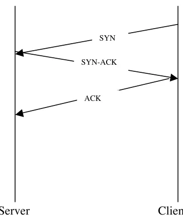
The TCP connection is established through a three-way handshake. To establish a
connection:
1. The client sends a SYN specifying the port number of the server that the client
wants to connect to. The SYN contains the client’s initial sequence number. SYN
2. The server responds with a SYN segment containing the server’s initial sequence
number. The server also acknowledges the client’s SYN by ACKing the client’s
ISN plus one. Hence this segment is called a SYN/ ACK. A SYN consumes one
sequence number.
3. The client must acknowledge this SYN from the server by ACKing the server’s
ISN plus one.
The side that sends the first SYN performs an active open. The other side that receives
the SYN and sends the next SYN-ACK performs passive open. The sequence numbers
are used to distinguish between packets from different connections. The sequence
numbers prevent packets delayed on the network from being delivered later and then
misinterpreted as a part of the existing connection. To establish a connection one of the
ends that a SYN chooses an initial sequence number for that connection. The ISN- initial
sequence number should change over time so that each connection has a different ISN.
SYN
SYN-ACK
ACK
Figure 1: Three-way handshake for connection establishment Client
According to RFC 793 the ISN should be a 32 bit counter that increments every 4
microseconds.
3.3.1.1 Time out of connection establishment
The connection fails to be established in certain situations. The sending side can only
identify a missing SYN/ ACK and cannot distinguish between the server being down or
the SYNs getting lost on the network. If a connection fails be established for some
reason, the client’s TCP continues to retransmit the SYN segments. Most Berkeley
derived systems set a time limit of 75 seconds on the establishment of a new connection.
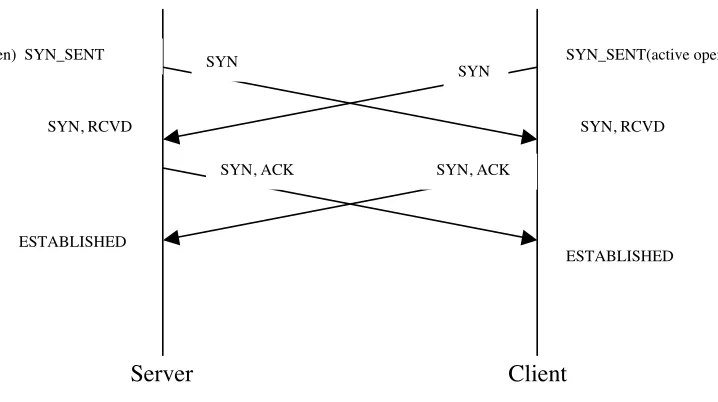
3.3.1.2 Simultaneous Open
In the event when both sides try to perform an active open at the same time it is called
simultaneous open. In active open each end transmits a SYN and the SYNs pass each
other on the network. For simultaneous open it is also required that each end have a
well-known local port number.
The state transitions for a simultaneous open are shown below. Both ends send the SYN
at the same time and enter the SYN_SENT state. When both ends receive the SYNs they
change their state to SYN_RCVD and each end resends the SYN and acknowledges the
received SYN. When both ends receive SYN/ ACK they change their state from
SYN_RCVD to ESTABLISHED.
TCP has been designed to handle simultaneous opens. The rule for simultaneous open is
that only one-connection results from it and not two. A simultaneous open involves the
exchange of four segments, one more than the three way normal handshake. The diagram
3.3.2 Data Flow
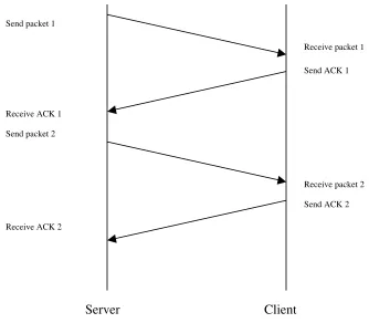
TCP is a reliable transmission control protocol. It provides reliable delivery of data from
one machine to another without duplication or loss of data. TCP uses positive
acknowledgement with retransmission. Positive acknowledgement with retransmission
requires the sender and the receiver to communicate to each other while sending data.
The sender after transmitting data waits for an acknowledgement from the receiver to
indicate a successful transfer of data. The receiver acknowledges every single byte that it
receives from the sender. A missing acknowledgement indicates a loss of data and causes
the sender to retransmit the data. The sender keeps a record of each packet it sends after
sending a packet the sender waits for an acknowledgement to arrive from the receiver
before sending the next packet. The sender also starts a timer when it sends a packet and
retransmits a packet if the timer expires before an acknowledgement arrives. In the event
of the packet or the acknowledgement getting lost or in the event of congestion on the
network, the timer expires causing the sender retransmit the packet.
SYN
SYN
SYN, ACK SYN, ACK
(active open) SYN_SENT SYN_SENT(active open)
SYN, RCVD SYN, RCVD
ESTABLISHED
ESTABLISHED
Figure 2: Simultaneous open
To avoid confusion caused by delayed or duplicated acknowledgements, positive
acknowledgements protocols send sequence numbers back in acknowledgements, so the
receiver can correctly associate acknowledgements with packets.
TCP uses sliding window for flow control. Sliding window makes stream transmission
more efficient it allows the sender to transmit multiple packets before it stops and waits
for acknowledgement. The number of packets sent on the network at one time depends on
the number of packets in the window. TCP uses cumulative ACKs, they acknowledge
that the receiver has correctly received all bytes up through the acknowledged sequence
number minus one.
In sliding window the number of packets put out on the network at one time is the
number of packets in the window at that time. Sliding window operation is similar to
Send packet 1
Receive packet 1
Send ACK 1
Receive packet 2
Send ACK 2 Receive ACK 1
Send packet 2
Receive ACK 2
having a sequence of packets to be transmitted to be inside a window. The protocol
places a small fixed size window on the sequence and transmits all packets that lie inside
the window. The sender and receiver buffer and the congestion on the network determine
the window size. The sliding window moves right after it receives an acknowledgement
and it increases the window depending on the receiver and sender buffer size and
congestion on the network. A packet that has been transmitted but not acknowledged is
called unacknowledged. The number of unacknowledged packets at any given time is
constrained by the window size and is limited to a small fixed number. Once the sender
receives an acknowledgement for the first packet inside the window, it “slides” the
window along and sends the next packet. The window continues to slide as long as the
acknowledgements are received. A well-tuned sliding window can keep the network
completely saturated. The performance of the sliding window depends on the window
size and the speed at which the network accepts packets. A sliding window has
substantially higher throughput than a simple positive acknowledgement protocol.
The sequence of packets in the window is partitioned into three sets. The packets that
have been successfully transmitted, received and acknowledged are to the left of the
window, the packets that have not yet been transmitted are to the right of the window and
the packets that lie in the window are the ones to be transmitted. A sliding window
protocol keeps a record of the packets that have been acknowledged and keeps a separate
timer for each unacknowledged packet. If the timer expires the packet is assumed lost and
Window size
sent and acknowledged sent but not acked ready to send can send after window slides
The sliding window varies over time. The number of packets in the window depend on
the receiver and the sender buffer size and congestion on the network. Each
acknowledgement, specifies the number of octets received, contains a window
advertisement that specifies the number of additional octets of data the receiver is
prepared to accept. The advantage of using a variable size window is that is provides flow
control as well as reliable transfer. In the event of the receiver’s buffers becoming full, it
sends a smaller window advertisement. In the extreme case the receiver advertises a
window size of zero to stop all transmissions. When the buffer becomes available the
receiver advertises a nonzero window size to trigger the flow of data. The window size is
determined by :
Window size =
(receiver window, sender window) (1)3.3.2.1 Bandwidth delay product
The size of the ideal window can be calculated for maximizing throughput. The
bandwidth delay product is given by
Capacity (bits) = bandwidth (bits/sec) x round trip time (sec) (2)
4 5 6 7 8 9
1 2 3 10 11 12…
The value of the bandwidth delay product depends on the network speed and the RTT
between the two ends.
3.3.2.2 Acknowledgement and Retransmission
Here we describe the bulk data flow using TCP with acknowledgement and
retransmission. The size of the packets that TCP sends is not fixed. The data is sent in
variable length segments. The number of packets sent at any given time depends on the
size of the sender window at that instant. The window keeps sliding as
acknowledgements arrive. The Acknowledgements refer to number of bytes received and
does not refer to datagrams or sequence numbers. The receiver uses the sequence number
of the packets to reorder the segments. At any time the, the receiver will reconstruct zero
or more octets contiguously from the beginning of the stream. The receiver always
acknowledges the longest contiguous prefix it received. Thus, the sender receives
continuous feedback from the receiver, a TCP acknowledgement specifies the sequence
number of the next octet that the receiver expects to receive.
TCP acknowledgement scheme is cumulative. Cumulative acknowledgement has both
advantages and disadvantages. The advantages are that the acknowledgement are easy to
generate and unambiguous. Another advantage is that lost acknowledgements do not
necessarily force retransmission. A major disadvantage is that the sender does not receive
information about all successful transmissions, but only a single position in the stream
that has been received.
TCP lacks the ability to distinguish between a lost packet or a lost acknowledgement or
timer expiration due to congestion on the network. In case the sender does not receive
retransmits the packet. If the receiver had already received the packet and the
acknowledgement was lost then the receiver checks for duplicate or triplicate packets and
then discards them. In the event of congestion of the network, the packets will take longer
to arrive at the destination this may cause the timer to expire and in turn trigger the
retransmission of the packet.
3.3.2.3 Timeout and Retransmission
The TCP at the sender after transmitting a packet starts a timer and waits for an
acknowledgement from the destination to indicate that the data was successfully received.
If the timer expires before the sender receives an acknowledgement, TCP assumes the
packet to be lost or corrupted and retransmits it.
The timeout timers of TCP are based on the Round Trip Time (RTT) of the packet. The
Internet is composed of various networks. A segment travelling from one machine to
another on the Internet may traverse through different networks a low delay network or a
high-speed network. The packet passes through multiple routers on way to its destination
hence it is impossible to know the exact arrival time of the ACKs at the source.
Furthermore, the packet might get queued at the routers and the delay at each router
depends on traffic, so the total time required for a segment to travel to the destination and
an acknowledgement to return to the source varies from one instant to the other. Since the
routes might change dynamically over the Internet and the traffic might change. TCP is
designed to accommodate the vast differences in the time required to reach various
destinations and the changes in time required to reach a given destination as traffic load
3.3.2.4 Round Trip Time Measurement
TCP records the time at which each segment is sent and the time at which each
acknowledgement that covers the sequence number of the segment arrives for the data in
that segment. From the two times, TCP computes an elapsed time known as a sample
round trip time or round trip sample. Normally there isn’t a one to one correspondence
between data segments and their ACKs. The ACKs are cumulative hence the above
method does not give us the correct RTT. The TCP specification specifies a smoothed
RTT estimator. Where a is the smoothing factor, the recommended value of a is 0.9.
RTT= (a * old_RTT) + ((1 - a) * New_Round_Trip_Sample) (3)
According to the specifications
RTT= (0.9* old_RTT) + (0.1 * New_Round_Trip_Sample) (4)
The smoothed RTT is updated every time a new measurement is made. Ninety percent of
the estimate is from the old samples and ten percent is from the new measurement.
Choosing a value of a close to 1 makes the weighted average immune to changes that last
a short time. Choosing a value for a close to 0 makes the weighted average respond to
changes in delay very quickly.
TCP calculates the timeout value based on the Round Trip Time estimate every time it
sends out a packet. RFC 793 recommended the transmission time out value to be
calculated using a constant weighing factor, b (b > 1), where b is the delay variance
factor. The retransmission timeout value is calculated as.
The recommended value of b is 2 however choosing the value of b can be difficult. To
detect packet loss quickly the timeout value should be close to the current RTT (i.e., b
should be close to 1). Detecting packet loss quickly improves throughput since TCP will
not wait unnecessarily long time before retransmitting. If b=1, any small delay will cause
a retransmission which will waste network bandwidth. The original specification
recommended setting b=2. In essence to accommodate the varying delays encountered in
an environment. TCP uses an adaptive retransmission algorithm that monitors delays on
each connection and adjusts its timeout parameters accordingly.
3.3.2.5 Accurate Measurement of Round Trip Sample
Measuring Round trip sample is complicated because TCP uses cumulative
acknowledgement scheme in which acknowledgement refers to data received. TCP
suffers from acknowledgement ambiguity. TCP sends data in the form of a segment in a
datagram. In the event of retransmission TCP sends data in the form of a segment in a
second datagram. Since both datagrams contain the same data, the sender has no way of
knowing whether an acknowledgement corresponds to the original or retransmitted
datagram.
Associating the acknowledgements to belong to earliest transmission or the
retransmissions is problematic. TCP measures the time it sends a packet out on the
network, in the event of retransmission the acknowledgement arrives after the
retransmissions, If TCP was to measure the round trip sample from the original
transmission and the time of arrival of the acknowledgement of the retransmitted packet,
it would cause the RTT to grow excessively long. Since the timeout keeps increasing it
causes the RTT to keep increasing. Associating the acknowledgements with the most
a segment arrives the receiver sends back an acknowledgement in case the delay timer
expires before the acknowledgement arrives TCP retransmits the segment. If shortly after
the retransmission the original acknowledgement arrives and is associated with the
retransmission this would cause the RTT to become very small.
Ignoring acknowledgements causes problems since the RTT estimates never gets
updated. To avoid this TCP uses timer backoff strategy, according to this strategy if the
timer expires causing a retransmission then TCP increases the timeout. Each time a
segment is retransmitted TCP increases the timeout (most implementations limit time out
to an upper bound that is larger than the delay along any path in the internet).
Most implementations use a multiplicative factor g to compute backoff.
New_timeout = g * timeout (6)
Typically g is equal to 2. Karn’s algorithm in essence states that “when computing the
round trip estimate, ignore samples that correspond to retransmitted segments, but use a
back off strategy, and retain the timeout value from the retransmitted packet for
subsequent packets and a valid sample is obtained”.
3.3.3 Congestion Control Algorithm
Congestion on the Internet implies delay caused by excessive traffic on the network at
one or more switching points. With increase in network traffic congestion occurs, delays
increase and routers begin to enqueue datagrams till they can route them. In the event of
excessive congestion queuing occurs and since each router has finite storage the routers
might begin to drop packets if the buffer gets filled. Currently TCP does not preallocate
resources to individual TCP connections hence each datagram competes for that storage.
the only way the notice congestion is by delayed data segments. In case of excessive
delay the retransmit timer will expire at the sender causing the sender to retransmit the
segment. Retransmissions increase the traffic on the network and hence aggravate the
congestion instead of alleviating it. The increased traffic will produce increased delays,
leading to increased traffic and so on and congestion collapse will occur.
To deal with congestion control and to avoid congestion collapse TCP should reduce its
transmission rates when congestion occurs. Transport protocols like TCP can help avoid
congestion by automatically reducing transmission rates whenever delay occurs.
Congestion control algorithms have to be designed carefully because Internet exhibits
wide variations in round trip delays.
3.3.3.1 Congestion Avoidance Algorithm
To avoid congestion TCP uses two techniques slow start and multiplicative decrease.
Slow start is an algorithm that operates by observing the rate at which packets should be
injected in the network. According to slow start the packets should be injected in the
network at the rate at which acknowledgements are returned to the sender.
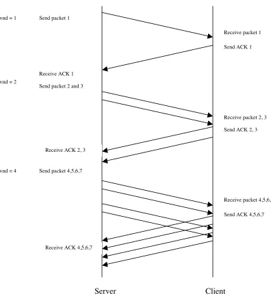
Slow start uses another variable and it is called congestion window or cwnd. When a new
connection is established the congestion window of the sender is initialised to one
segment. Each time an ACK is received, the congestion window is increased by one
segment. Congestion window is maintained in bytes, but slow start increments in terms of
segment size. The sender can transmit the minimum of the congestion window and
advertised window and is given by
In the steady state i.e. in case of no congestion, the congestion window is the same size as
the receiver’s window. Reducing the congestion window reduces the traffic TCP injects
into the connection. The sender initially sends one segment out, on receiving an ACK the
sender increments its window to two and sends two segments out. After the two segments
are acknowledged the sender increases its window to four, hence providing an
exponential increase. (The figure given below has been taken from “Introduction to
TCP/IP” by Comer)
Send packet 1
Receive packet 1
Send ACK 1
Receive packet 2, 3
Send ACK 2, 3 Receive ACK 1
Send packet 2 and 3
Receive ACK 2, 3 cwnd = 1
cwnd = 2
cwnd = 4 Send packet 4,5,6,7
Receive packet 4,5,6,7
Send ACK 4,5,6,7
Receive ACK 4,5,6,7
Slow start is used to initiate data into the network across a connection. When the limit of
the network is reached congestion avoidance deals with lost packets. The congestion
control algorithm assumes that the packet loss caused due to corruption and then discard
is less than 1% and hence the main cause of packet loss is assumed to be network
congestion between the source and the destination. A sender recognizes congestion on the
network by either a time out occurring or arrival of three duplicate ACKs.
Congestion avoidance is invoked when there is congestion on the network and slow start
is invoked when traffic has to be introduced on the network again. Congestion avoidance
and slow start are separate algorithms but are implemented together. Congestion
avoidance and slow start require two variables to be maintained for each connection and
they are congestion window, cwnd, and a slow start threshold size, ssthresh.
The working of the algorithm is as follows:
1. cwnd is set to one segment and ssthresh is set to 65535 bytes on initialisation of
the connection.
2. The window size for the TCP connection is determined by the following formula:
3. Allowed_window = min (receiver_advertisement, congestion_window)
4. Congestion avoidance is based on the perceived network congestion and the
advertised window size is determined by the amount of buffer available at the
receiver.
5. Congestion causes one half of the current window size to be saved into ssthresh.
If the time out timer expires cwnd is set to one segment.
6. Acknowledgement of new data causes cwnd to be increased depending upon
whether slow start or congestion avoidance is being performed.
{
/ *Do slow start */
/* slow start causes the window to increase exponentially every time an ACK is received
*/
}
else
{
/*do congestion avoidance */
/*congestion avoidance causes the window to increase additively i.e. it increases the
window by 1/cwnd every time an ACK is received */
}
Given below are the pseudo codes for fast retransmit and fast recovery algorithm
Combined slow start, congestion avoidance
algorithm (Tahoe)
Create a second state variable, ssthresh, to
switch between the two algorithms.
Assume the wnd = min (cwnd, advertised window)
On a timeout
ssthresh= wnd/2
cwnd=1
When a new ACK arrives
If(cwnd<=ssthresh)
/*open the window exponentially*/
else
/*otherwise do congestion Avoidance increment
linearly*/
cwnd=cwnd+1;
Fast Retransmit:
If three or more duplicate ACKs arrive at the
sender, this is a strong indicator that a packet
was dropped.
The sender retransmits without waiting for the
retransmit timer.
Fast Recovery:
After a fast retransmit, the sender goes to
congestion avoidance rather than slow start.
Enhanced algorithm:
When the third duplicate ACK arrives
Set ssthresh = cwnd/2;
Retransmit the segment
Set cwnd= ssthresh + 3 packets
For each additional duplicate ACK (after the
third duplicate ACK) increment cwnd by 1 and
transmit a new packet (if allowed by the new cwnd
value)
When the next ACK arrives that acknowledges new
Slow start increase, multiplicative decrease, congestion avoidance, measurement of
variation and exponential timer backoff improves the performance of TCP without
significant overhead.
3.3.4 Connection Termination Protocol:
TCP requires four segments to terminate the connection. The TCP connection is fully
duplex, data flows in both directions independently. Since the connection is full duplex
the data flow in each direction should be shut down independently to close the
connection. A communicating host after it finishes sending data can send a FIN to close
the flow of data in that direction or half close the TCP connection. The other host on
receiving a FIN ACKs it and notifies the application of the termination of data flow in
that direction. The receipt of a FIN indicates that there will be no more data flowing in
that direction. However the data can continue to flow in the other direction till the
connection is closed in that direction.
The end that first issues the close i.e. the end that sends the first FIN is said to perform
active close and the end that receives the FIN does a passive close. When an end receives
a FIN it responds with an ACK of the received sequence number plus one. A FIN
consumes a sequence number, just like a SYN. In a server client scenario, when the client
finishes it sends a FIN to the server and the server responds with an ACK thus closing the
flow of data in that direction. The connection is now in the half close state and data still
continues to flow from the server to the client. When the server’s TCP delivers an end of
file to the application it causes the server to close its connection causing its TCP to send a
FIN, The client’s TCP responds with an ACK by incrementing the received sequence
number by one. The TCP connection is now fully closed. The diagram below shows a
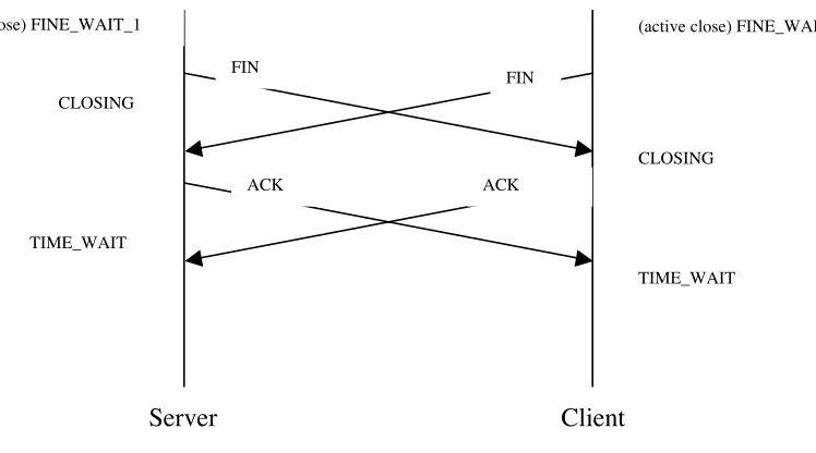
3.3.4.1 Simultaneous Close
When both ends of a connection try to perform an active close, it is called simultaneous
close. When the application issues a close. both ends move from ESTABLISHED to
FIN_WAIT_1. This causes both the FINs to be sent.. When the FIN is received each end
transitions from FIN_WAIT_1 to the CLOSING state, and each state sends its final ACK.
When each end receives the final ACK, the state changes to TIME_WAIT.and the
connection is closed.
FIN
FIN Ack of FIN
Ack of FIN application close
deliver EOF to application
application close
The same numbers of segments are exchanged as in the normal close.
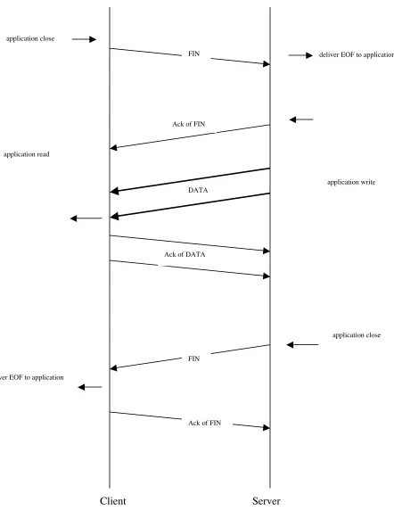
3.3.4.2 TCP Half close
The TCP connection is a full duplex connection i.e. data can flow in both directions
independently. To completely close a TCP connection, the connection has to be closed in
both directions. One of the main features of TCP is its capability to let one end of the
connection terminate its output, while continuing to receive data from the other end. This
is called TCP half close. In the diagram below the client sends FIN and it the server sends
an ACK of FIN but the server can still continue to send data from the server end to the
client. When the end that received half close is done sending data it closes its end of the
connection causing a FIN to be sent and this delivers an end-of-file application that
initiated the half close. When the second FIN is acknowledged the connection is
completely closed.
FIN
FIN
ACK ACK
(active close) FINE_WAIT_1
CLOSING
TIME_WAIT
(active close) FINE_WAIT_1
CLOSING
TIME_WAIT
application close
deliver EOF to application
application write Ack of FIN
Ack of FIN FIN FIN
DATA
Ack of DATA
application close application read
deliver EOF to application
Figure 8: TCP Half Close
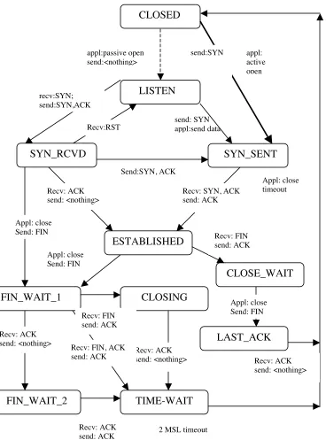
3.3.5 TCP finite State Machine CLOSED LISTEN SYN_SENT SYN_RCVD ESTABLISHED recv:SYN; send:SYN,ACK
Recv:RST send: SYNappl:send data
appl:passive open send:<nothing> send:SYN appl: active open FIN_WAIT_1 FIN_WAIT_2 TIME-WAIT CLOSING CLOSE_WAIT Appl: close Send: FIN Recv: ACK send: <nothing> Recv: ACK
send: ACK 2 MSL timeout
Recv: ACK send: <nothing> Recv: ACK
send: <nothing>
Recv: SYN, ACK send: ACK
Appl: close Send: FIN
Recv: FIN, ACK send: ACK Send:SYN, ACK Recv: FIN send: ACK Appl: close Send: FIN Recv: FIN send: ACK Recv: ACK send: <nothing> Appl: close timeout LAST_ACK
3.4.6 Challenges faced by TCP in mobile environment
The mobile hosts expect the same type of service as the fixed hosts on the wired
network. Using standard TCP leads to severe drop in the throughput.
3.4.6.1 High Bit Error Rate.
The wireless link suffers from a high bit error rate. The high bit error rates corrupt the
packets. The receiver discards an erroneous packet and this causes the sender to retransmit
the packet. TCP’s uses a sliding window mechanism to accomplish reliable, in-order
delivery and flow congestion control. The window size is determined by the minimum of
receiver’s advertised buffer space and perceived network congestion. The sender allows
up to “the window size” outstanding or unacknowledged packets at a time. This results in
a usable window size of “Window size”- no of outstanding packets. On detecting a
missing acknowledgement by detecting three duplicate acknowledgements or the sender’s
retransmission timer timing out, the sender retransmits the segment and exponentially
backs off its retransmit timer and closes its congestion window. Standard TCP attributes
any loss to a loss due to congestion and moves into slow start reducing the number of
packets it can send out on the network. Repeated errors therefore cause a low throughput.
The erroneous packets cause end-to-end retransmission hence causing a traffic overload
over the entire network. Hence the high Bit Error Rate of the wireless link decreases the
throughput of the connection and increases the traffic on the network by causing
end-to-end retransmissions.
3.4.6.2 Capacity
Bandwidth and capacity are limited for a given application on the wireless link. Hence
3.4.6.3 Error Profile
The error profile of the wireless link is bursty and not uniform. Errors may depend on the
position of the user. There could be severe fading due to diffraction and multipath.
3.4.6.4 Frequent Disconnections
In the wireless environment the received power by a mobile device changes with respect
to its position in the cell. Handovers cause variations in packet delay and can cause
disconnections. The mobile device can temporarily be disconnected and can come back
up hence causing an end-to-end retransmission of all the packets that arrived during its
temporary disconnection. If there are many users in a cell, an established connection is
given priority over a new connection or a connection to be handed over hence some
connections may not receive bandwidth for quite some time. The call-blocking event is a
disconnection. These disconnections cause TCP to time out and lower its congestion
window. Hence the efficiency of TCP is reduced greatly.
TCP was designed for wired, fixed and reliable topologies. TCP attributes all losses to
congestion on the network. Even if a single packet is dropped, TCP assumes the loss was
due to congestion and throttles the transmission by bringing the congestion window to the
minimum size and then moves into slow start. The sender unnecessarily holds back
slowly growing the transmission rate, even though the receiver recovers quickly from the
short temporary disconnection. Hence the network capacity remains unutilised.
1.4.6.5 Mobility
Motion across wireless cell boundaries causes increased delays and packet losses while
network learns how to route these packets to the host’s new location. TCP interprets these
4 Assumptions
Listed below are some of the assumptions made for the design of the protocol.
4.1 Mobile IP
Several mobile IP schemes have been proposed to allow routing of IP datagrams to
mobile hosts. Here the working of mobile IP is briefly explained. To route packets on the
Internet the routers look at the destination address of the incoming packets and forwards
them according to internal look up tables. As long as receiver can be reached within its
physical subnet, it gets the packets; as soon as it moves out of the subnet, no packet will
reach it anymore. Hence the hosts need a topologically correct address at all times.
Mobile IP supports end system mobility while maintaining scalability, efficiency and
compatibility in all respects with existing applications and Internet protocols.
4.2
High BER
The Wireless Environment for 4G will be characterized by a high bit error rate.
4.3 Link Layer Protocols and Forward Error Correction
The link layer protocols and the forward error correction mechanism would either correct
5 Algorithms for optimised transport layer protocols for
wireless systems
.
The numbers of errors increase over the wireless link due to the unreliability of the link
or the high bit error rate. Various new versions of TCP have been introduced in order to
cope with the problems related to the behavior of TCP over high error rate system. A few
solutions have been listed here with their various advantages and disadvantages.
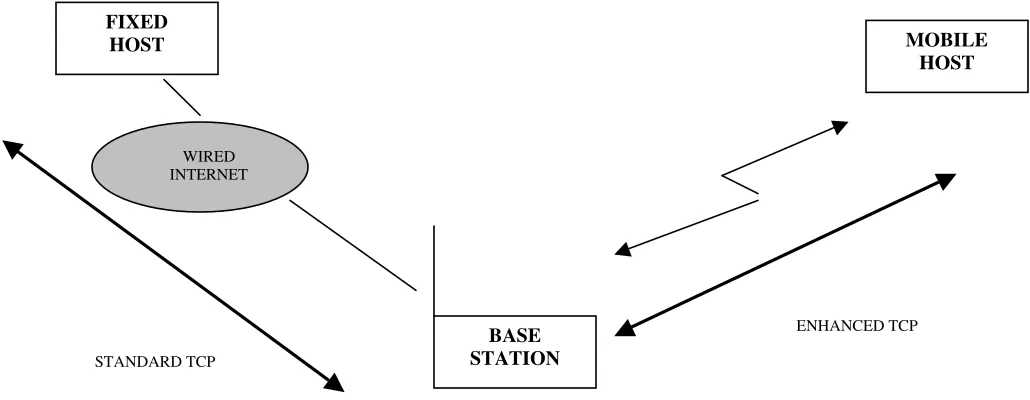
5.1 Indirect TCP
Indirect TCP was one of the earliest approaches using the split protocol model. I-TCP
splits the connection into two sub-connections. Indirect TCP is based on an indirect
protocol model. I-TCP is a reliable stream-oriented transport layer protocol for mobile
hosts. In this approach an end-to-end TCP connection between a fixed host and a mobile
host is split into two separate connections.
1. A regular TCP connection between the fixed host and the mobility support router
(base station) currently serving the mobile host and
2. A wireless TCP connection between the mobility support router (base station) and
mobile host.
!
MOBILE
HOST MSR
WIRED INTERNET
STANDARD TCP
WIRELESS TCP
FIXED HOST
I-TCP is fully compatible with TCP/ IP on the fixed network and is built around the
following simple concepts.
1. A transport layer connection between an MH and an FH is established as two separate
connections- one over the wireless medium and another over the fixed network with
the current MSR being the intermediate point.
2. If the MH switches cells during the lifetime of an I-TCP connections, the centre point
of the connection moves to the new MSR.
3. The FH is completely unaware of the indirection and is not affected even when the
MH switches cells, i.e. when the intermediate point of the I-TCP connection moves
from one point to another.
When a mobile host wants to communicate with some fixed host using I-TCP a request is
sent to the current MSR to open a TCP connection with the fixed host on behalf of the
mobile host. The MH communicates with its MSR on a separate connection using a
variation of TCP that is tuned for wireless links and is aware of mobility.
The MSR acts as a proxy and buffers data. When a fixed host sends a packet the MSR
buffers it and acknowledges it. Then the MSR tries to forward the packet to the mobile
host. The acknowledgement from the Mobile host is used by the MSR. If the packet it
lost on the wireless link the fixed host would not notice it, as the packet would be
retransmitted by the MSR. When the mobile host sends a packet to the fixed host, the
MSR buffers it and acknowledges it. If the packet is lost on the wireless link the Mobile
host retransmits the packet. However, if the packet it lost on the wired link, the MSR
retransmits it to the fixed host.
5.1.1 I-TCP Components
1. MH side: I-TCP can be accessed as a transport protocol by the applications
running on a mobile host using special library calls. These library calls are similar
in the interface they provide and the function they perform.
2. MSR side: Most of the functionality for supporting I-TCP connections lies with
the MSR. The handoff support for the I-TCP connections is implemented in the
MSR kernel.
5.1.2 Establishing an I-TCP connection
To establish an I-TCP connection with a fixed host the mobile host sends a request to the
base station, the MSR under which the mobile host is currently registered performs the
following steps:
1. The base station establishes a regular TCP connection with the FH named in the
request on behalf of the MH using the IP address and port number of the MH for local
endpoint parameters. This is the wired part of the I-TCP connection. Hence the TCP
connection is characterized by:
<fh-address, fh-portnumber> <mh-address, mh-portnumber>
2 . Another connection is then established between the MSR and the MH using a
transport layer protocol tailored for mobile hosts and wireless links. This forms the
wireless part of the I-TCP connection. This connection is characterized by:
<msr-address, msr-portnumber> <mh-address, mh-portnumber>
5.1.3 Handing off I-TCP connection
A mobile host that had established a connection with a fixed host through MSR-1 moves
to another cell under MSR-2. When a MH requests a connection with the FH while
located in the cell under MSR-1, MSR-1 establishes a socket with the MH address and
socket with its own address and some suitable port number for the wireless side of the
I-TCP connection to communicate with the MH.
When the MH switches cells, the state associated with the two sockets of the I-TCP
connection at MSR-1 is handed over to the new MSR (MSR-2). MSR-2 then creates two
sockets corresponding to the I-TCP connection with the same end point parameters that
the socket at MSR-1 had associated with them. Since the connection end points do not
change there is no need to re-establish a new connection.
5.1.4 Advantages of I-TCP
There are various advantages of I-TCP and they are:
1. Implementing I-TCP does not require any changes in the TCP protocol as used by the
hosts in the fixed network. The fixed network protocol stays unchanged.
2. The data gets buffered at the bases station the point at which the connection is split.
The loss of packets on the wireless link cause the base station to locally retransmit
instead of retransmission from the fixed host, thus increasing the throughput by local
retransmission and by not increasing the traffic on the fixed network. Due to strict
partitioning into two connections, transmission errors on the wireless link cannot
propagate into the fixed network.
3. An optimized version of TCP can be used on the wireless link that is best suited for
the wireless link. The wireless TCP version can use precise timeouts to ensure
retransmission as fast as possible.
4. Standard TCP can be used on the fixed link and an optimized version of TCP can be
used on the wireless link. Hence partitioning the connection into two connections
provides the flexibility to use a different transport layer protocol between the foreign
5.1.5 Disadvantages of I-TCP
The various disadvantages with I-TCP are
1. The biggest disadvantage of TCP is the loss of end-to-end semantics of TCP. The
base station ACKs the packets sent by the fixed host this might cause problems if
the base station partitioning the TCP connection crashes because receiving an
acknowledgment only means that the foreign agent received the packet and does
not mean that the mobile host received the packet.
2. The base station buffers the packets that it receives from the fixed hosts and then
transmits the packet over the wireless link to the mobile device. Increased
handover latency in I-TCP causes problems since all the packets that are sent by
the correspondent node and the packets that arrive at!! the foreign agent are
buffered. The foreign agent removes a packet from the buffer as soon as it
receives an acknowledgement from the mobile node. However during a handover
to another foreign agent there will be a blackout period before the foreign agent
starts forwarding the packets to the new foreign agent. In the event of increased
traffic and a temporary black out of the mobile host can cause the base station to
drop the packets. Since the dropped packets have already been acknowledged by
the base station the fixed host will not retransmit and the mobile host will not
receive the packets. This occurs due to the lack of linkage between the throughput
of the TCP connection and the size of the receiver buffer at the base station.
3. To incorporate any means of security in the TCP connection between the fixed
host and the mobile host the foreign agent will have to be integrated in all the
security mechanisms.
5.2 TCP Freeze
TCP freeze maintains the end-to-end semantics of the transport layer protocol and does
not require the involvement of intermediaries as the base station for flow control. Freeze
TCP involves the client to indicate an impending disconnection or a handoff. A mobile
node continuously monitors the received signal strength, a change in received power
gives the mobile host the capability to signal an impending hand off or a disconnection.
The mobile device indicates a pending disconnection by sending a zero window
advertisement. The mobile node advertises a window size of zero to force the sender into
Zero Window Persist or ZWP mode and prevent it from dropping its congestion window.
To implement freeze TCP only the client’s code has to be changed and hence there is no
need for an intermediary. Freeze TCP uses TCP’s ability to gracefully recover from a
zero persist mode. The receiver advertises a window size of zero to the sender on
detecting the signal fading, the sender sets its window to zero and enters persist mode. It
also freezes all packet retransmit timers and does not drop the congestion window so that
the idle time during the slow start phase can be avoided. The receiver starts advertising a
window size of zero on sensing an impending disconnection at the beginning of the
warning period. The duration of the warning period is RTT. Experimental data indicates
that warning periods greater or shorter than RTT led to worse average performance.
Since the probes are exponentially backed off, there is a possibility of substantial ideal
time after a reconnection. This could happen if the disconnection period is long and the
reconnection happens immediately after losing a ZWP from the sender. In such a case the
sender will go into a long backoff before sending the next probe. Meantime the receiver
reconnects but the connection remains idle until the sender retransmits its next probe. To
copies of the ACK for the last segment it received prior to disconnection. This is
abbreviated as “TR-ACKs”.
5.2.1 Performance gain possible due to freeze TCP
(Figure taken from “Freeze TCP: A true end-to-end TCP enhancement mechanism for
mobile environments” by Tom Goff, James Moronski, D.S.Pathak)
!
Ts: is the time required to “put the packet on the wire.
W unACKed packets Can be sent
ts
RTT
RTT: is the total round trip delay including the ts delays at sending, receiving as well as
any intermediate nodes.
W: sender’s window.
To avoid any ideal period:
W. ts ≥ RTT or W≥ RTT/Ts (8)
Ts= packet-size/ bandwidth (9)
Assuming RTT/ts >> 1; W>>1 is required for full network utilization.
The number if extra packets transferred by freeze TCP scheme is given by:
Extra Segments = W^2/8 + W log W – 5W/4 + 1 (10)
5.2.2 Advantages of TCP Freeze
Freeze TCP enhances the throughput of TCP in the presence of frequent disconnections
(and reconnections), which characterize mobile environments. It is an end-to-end
signalling protocol and does not require any intermediaries to participate in flow control.
It does not require any changes in the TCP code on the sending side. There is little
overhead with this protocol.
5.2.3 Disadvantages of TCP Freeze
TCP freeze requires that network stacks be aware of mobility. A drawback on the
protocol is that it requires the receiver to predict the impending disconnection. If the
disconnection cannot be predicted then the behaviour and performance of the protocol is
5.3 Snooping TCP
Snoop TCP is also a split protocol. Snoop TCP requires involvement of an intermediary.
In snoop TCP, the foreign agent or the base station buffers all packets with destination
mobile host and snoops the packet flow in both directions. The foreign agent or the base
station snoops the data to recognize acknowledgements. The base station buffers the data
to be able to perform fast local retransmission in case of packet loss on the wireless link.
In this approach the foreign agent buffers all packets until it receives acknowledgment
from the mobile host. After the base station or the foreign agent receives an
acknowledgement from the mobile host it removes the packet from its buffer. If the
foreign agent does not receive an acknowledgement from the mobile host within a certain
period of time, then it assumes that either the packet or the acknowledgement is lost. The
arrival of three duplicate acknowledgements also indicates the loss of the packet. The
base station then performs retransmissions directly from the buffer, thus performing a
much faster retransmission. The time out for acknowledgements can be set much shorter,
for it reflects only the delay of one hop plus processing time.
Snoop TCP maintains the end-to-end semantics by not acknowledging the packets. The
foreign agent however filters duplicate acknowledgements to avoid unnecessary
retransmission of data from the fixed host. The foreign agent may discard packets already
retransmitted locally and acknowledged by the mobile host, thus reducing unnecessary
For data transfer from the mobile host with the destination fixed host works as follows.
The foreign agent snoops into the packets and on detecting a missing packet, it returns a
negative acknowledgement (NACK). On receiving the NACK the mobile host now
retransmits the missing packet. Reordering of packets is done automatically at the fixed
host.
5.3.1 Advantages of Snoop TCP
The various advantages of snoop TCP are
1. The end-to-end semantics are preserved in snoop TCP. The fixed host and the mobile
host never have an inconsistent view of the TCP connection as is possible with
I-TCP. Snoop TCP falls back to standard TCP when the enhancements stop working.
2. Since the packets are retransmitted locally from the base station it saves time and
reduces extra traffic on the network.
Local retransmission
End-to-End TCP connection
Figure 12: Snoop TCP setup (figure taken from Mobile Communications by Schiller)
MOBILE HOST
HOST
STANDARD TCP
WIRELESS TCP
Foreign Agent or Base Station
Snooping of ACKs and buffering of data
3. The code at the fixed host does not need to be changed as most of the enhancements
are in the foreign agent.
4. This approach does not need a handover of state as soon as the mobile node moves to
another foreign agent. If there is still data in the buffer of the foreign agent, a time out
at the fixed host would cause a retransmission of packets to the new care-of-address.
5. If a foreign agent does not use the enhancements then the approach automatically
falls back to the standard solution.
5.3.2 Disadvantages of Snoop TCP
The various disadvantages with Snoop TCP are
1. TCP snoop does not isolate the behavior of the wireless link from. In the event the
base station takes time to retransmit a packet, the fixed host in the meantime
might time out and trigger a retransmission. The quality of isolation depends on
the quality of the wireless link, time out values and further traffic characteristics.
2. Using NACK is an additional overhead on the mobile node and the protocol is no
longer transparent to the mobile host.
3 . This Technique will not work with Mobile IP since the IP header will be
encapsulated and it will no longer be possible for the foreign agent to snoop the
packets.
!
5.4 Mobile TCP
Mobile TCP similar to I-TCP splits the connection into two connections. A standard TCP
connection is established between the base station and the fixed host and another
optimized TCP connection is established between the base station and the mobile hosts.
M-TCP assumes a low bit error rate on the wireless link and hence the base station does
not buffer the data. In the event of loss of packet the packet is retransmitted from the