ABSTRACT
DU, JINMEI. Distribution of Liquid Drops on Solid Surfaces between Flat Surface and Fibers. (Under the direction of Dr. Stephen Michielsen and Dr. Hoon Joo Lee).
Understanding the ability of a liquid to transfer from a flat surface to fibers can provide basic
information enabling the design and preparation of superoleophobic or oil self-cleaning
materials. Based on the literature review, a Laplace pressure difference will change the shape
of droplet and even move it when the force caused by this pressure difference overcomes the
resistive forces such as gravitational and viscosity forces. The final shape and location of
droplets on different materials or different geometrical structures are determined by the
system free energy. Based on experimental observations and the predictions of the ability of a
liquid to transfer, it is found that the theory can be used to predict and explain low surface
tension liquid (oil) transfer and the final location of the liquid. It is also found that the height
of a fiber which is vertically attached on a flat surface should be longer than the length of the
drop on the fiber to prevent the drop wetting the flat surface; if a low surface tension liquid
on a flat surface touches a cylindrical fiber resting on the flat surface and normal to it, the
drop should move such that it lies on both the flat surface and the fiber. However, the liquid
does not climb the cylindrical fiber or transfer to its tip. If subsequently the fiber is raised,
then the droplet may remain with the flat surface, transfer to the fiber tip, or transfer to the tip
and the body of fiber. The theoretical equations derived from Carroll’s equation and our
experimental observations prove that droplets do move along a conical fiber. However, the
critical relationships between liquid motion and droplet size, surface tension, conical fiber
Distribution of Liquid Drops on Solid Surfaces between Flat Surface and Fibers
by Jinmei Du
A dissertation submitted to the Graduate Faculty of North Carolina State University
in partial fulfillment of the requirements for the degree of
Doctor of Philosophy
Fiber and Polymer Science
Raleigh, North Carolina
2010
APPROVED BY:
Dr. Stephen Michielsen Dr. Hoon Joo Lee
(Co-Chair of Advisory Committee) (Co-Chair of Advisory Committee)
DEDICATION
To
My Parents
and
BIOGRAPHY
Jinmei Du was born in Shandong, China. She attended Qingdao University in Textile
Chemistry department in 1998 and received her Bachelor degree in 2002. After that she
completed her study for Master degree in the same department in 2005. Jinmei continued her
education as a doctoral student in Fiber and Polymer Science under the direction of Drs.
Stephen Michielsen and Hoon Joo Lee in the College of Textiles at North Carolina State
University in 2007.
On July 2004, Jinmei married Changhai Xu who received his Ph.D degree in Fiber and
ACKNOWLEDGMENTS
I would like to express my sincerest thanks to my advisors Drs. Stephen Michielsen and
Hoon Joo Lee, who persevered with me throughout my educational experience and research
work as a student in the Fiber and Polymer Science program. I am also most appreciative of
the other members of my advisory committee, Dr. Keith Beck, Dr. Jan Ganzer and Dr.
Orlando Rojas, whose knowledge and expertise contributed to the completion of this
dissertation.
I would like to say thanks to my lovely husband Changhai Xu for everything. Without your
love, affection, constant support, and willingness to sacrifice, this goal could not have been
achieved. I love you with all of my heart. I am deeply grateful for parents whose early
instruction, love, support, and continued sacrifices have laid the foundation for all my
successes in life.
I would like to acknowledge my gratitude to my friends, who encouraged me during this
difficult process. Thank you so much for your time, your support, your well wishes, and your
TABLE OF CONTENTS
LIST OF TABLES ... vii
LIST OF FIGURES ... viii
Chapter 1 Introduction ... 1
Chapter 2 Literature Review ... 4
2.1. Introduction ... 4
2.2. Contact angle and wetting behavior ... 7
2.3. Liquid on solid surface ... 11
2.3.1. Liquid connected with reservoir on a solid surface ...11
2.3.2. Finite liquid droplet on a solid surface ... 13
2.3.3. Liquid on cylinder pulled out from reservoir ... 17
2.4. Laplace pressure of liquid on solid surface ... 18
2.4.1. Laplace pressure of liquid on flat surface ... 19
2.4.2. Laplace pressure of liquid on fiber tip ... 20
2.4.3. Laplace pressure of liquid on cylindrical fiber ... 21
2.4.4. Laplace pressure of liquid on conical fiber ... 23
2.5. Motion of a droplet on a conical fiber ... 26
2.6. Summary ... 31
Chapter 3 Experimental ... 34
3.1. Materials ... 34
3.2. Cleaning of materials ... 34
3.3. Drop transfer from one location to another ... 34
3.3.1. Drop transfer from flat surfaces to fiber tips or bodies ... 34
3.3.2. Drop transfer from fiber tips to bodies ... 35
3.3.3. Drop motion between flat surface and fiber ... 35
3.5. Drop dimensions prediction ... 36
Chapter 4 Results and Discussion ... 37
4.1. Laplace pressure and free energy of liquid on solid surfaces ... 37
4.1.1. Laplace pressure and free energy of liquid on flat smooth surfaces ... 38
4.1.2. Laplace pressure and free energy of liquid on a fiber body ... 39
4.1.3. Laplace pressure and free energy of liquid on both flat surface and fiber ... 40
4.1.4. Laplace pressure and free energy of liquid on the fiber tip ... 50
4.2. Liquid transferring from one location to another ... 58
Chapter 5 Liquid Moving on Conical Fibers ... 102
5.1. Factors influencing the Laplace pressure change ... 103
5.2. Motion of droplet on conical fiber ... 103
Chapter 6 Conclusions ... 107
Chapter 7 Future Work ... 109
References ... 110
LIST OF TABLES
Table 4.1. Dimensions of water drop on a Teflon® flat surface and a glass fiber. ... 46
Table 4.2. Dimensions of liquid drop on a Teflon® flat surface and a glass fiber. ... 47
Table 4.3. hC for EG and Kaydol drops on a Teflon® flat surface and a nylon fiber. ... 95
Table 4.4. hC for EG and Kaydol drops on a Teflon® flat surface and a PP fiber. ... 96
Appendix 1. ΔG and ΔP of water on a Teflon® flat surface and nylon fiber tip or body. ... 117
Appendix 2. ΔG and ΔP of EG on a Teflon® flat surface and nylon fiber tip or body. ... 118
Appendix 3. ΔG and ΔP of Kaydol on a Teflon® flat surface and nylon fiber tip or body. .... 119
Appendix 4. ΔG and ΔP of water on a Teflon® flat surface and glass fiber tip or body. ... 120
Appendix 5. ΔG and ΔP of EG on a Teflon® flat surface and glass fiber tip or body. ... 121
Appendix 6. ΔG and ΔP of Kaydol on a Teflon® flat surface and glass fiber tip or body. ... 122
Appendix 7. ΔG and ΔP of water on a Teflon® flat surface and PP fiber tip or body. ... 123
Appendix 8. ΔG and ΔP of EG on a Teflon® flat surface and PP fiber tip or body. ... 124
Appendix 9. ΔG and ΔP of Kaydol on a Teflon® flat surface and PP fiber tip or body. ... 125
Appendix 10. ΔG of water on a Teflon® flat surface and a nylon fiber. ... 126
Appendix 11. ΔG of EG on a Teflon® flat surface and a nylon fiber. ... 127
Appendix 12. ΔG of Kaydol on a Teflon® flat surface and a nylon fiber. ... 128
Appendix 13. ΔG of water on a Teflon® flat surface and a glass fiber. ... 129
Appendix 14. ΔG of EG on a Teflon® flat surface and a glass fiber. ... 130
Appendix 15. ΔG of Kaydol on a Teflon® flat surface and a glass fiber. ... 131
Appendix 16. ΔG of EG on a Teflon® flat surface and a PP fiber.... 132
Appendix 17. ΔG of Kaydol on a Teflon® flat surface and a PP fiber. ... 133
Appendix 18. ΔG of water on a PET flat surface and a nylon fiber. ... 134
Appendix 19. ΔG of EG on a PET flat surface and a nylon fiber. ... 135
Appendix 20. ΔG of water on a PET flat surface and a glass fiber. ... 136
LIST OF FIGURES
Figure 2.1. Schematics of a water drop on (a) Lotus leaf, and (b) Lady’s Mantle leaf14
. ... 4
Figure 2.2. Liquid droplet on flat surface. ... 8
Figure 2.3. Liquid droplet on a rough surface: (a) Wenzel model, and (b) Cassie-Baxter
model. ... 8
Figure 2.4. Schematics of spreading of a liquid contacted with a huge reservoir: (a) on a flat
smooth surface, and (b) on a cylinder. x0 is the liquid film thickness on cylinder. O and B are
the positions before and after spreading, respectively.... 12
Figure 2.5. Schematics of a liquid drop on a flat smooth solid surface: (a) before
spreading-spherical cap, and (b) after spreading-flat uniform film. The total flat surface areas
AS in (a) and (b) are same. ... 15
Figure 2.6. Schematics of a liquid drop on a cylinder: (a) before spreading, and (b) after
spreading. ... 16
Figure 2.7. Schematics of liquid on a cylinder pulled out from a reservoir: (a) flat uniform
film, and (b) undulating drop. ... 18
Figure 2.8. Schematics of the principal radii of curvatures of a liquid drop on a flat surface. 19
Figure 2.9. Schematics of the principal radii of curvatures of a liquid drop on fiber tip:
(a) drop contact line away from the edge of fiber tip, and (b) drop pinning at the edge. ... 20
Figure 2.10. Schematics of principal radii of curvatures of a liquid drop on a cylinder: (a) on
the convex part, and (b) on the concave part. ... 21
Figure 2.11. Schematic of a liquid drop on a conical fiber. Radius of the cone increases from
the tip to base of the cone (marked as y direction), and a is the half-angle of the cone. ... 24
Figure 2.12. Schematics of a drop on a cone: (a) liquid moving on the cone, and (b) the
magnification of liquid wedge of the moving drop. The drop moves with an average velocity
v along cone axis in the direction of increasing radius (marked as y), and it moves along the
cone surface with an instantaneous velocity u(ξ). ... 27
Figure 2.13. Schematic of a liquid drop on a titled conical fiber. Radius of the cone increases
from the tip to base of the cone (marked as y direction), and the cone is tilted at an angle β
Figure 4.1. Water droplet on a Teflon® flat surface and a glass fiber: (a) on flat surface, and
(b) on both flat surface and fiber. ... 41
Figure 4.2. Schematic of a droplet on both flat surface and fiber. ... 41
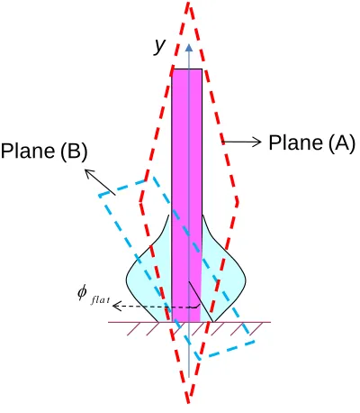
Figure 4.3. Schematic of angle ϕflat ... 42
Figure 4.4. Water droplets sitting on a Teflon® flat surface and in contact with a glass fiber
(rf = 0.233mm): (a) 0.5μL, (b) 2.0μL, and (c) 4.0μL. ... 46
Figure 4.5. Different droplets (2.0 μL) sitting on a Teflon® flat surfaces and in contact with
glass fibers (rf= 0.233mm): (a) water, (b) EG, and (c) Kaydol. ... 46
Figure 4.6. Water on a nylon fiber (rf = 0.143mm) and a Teflon® flat surface with volumes
(a) 2.0μL and (b) 4.0μL. ... 48
Figure 4.7. Different liquids of constant volume, V0 = 2.0μL, on a nylon fiber (rf = 0.143mm)
and a Teflon® flat surface: (a) water, and (b) Kaydol. ... 48
Figure 4.8. Water (V0 = 4.0μL) on a nylon fiber (rf = 0.143mm) and different flat surface:
(a) Teflon® and (b) PET flat surfaces. ... 49
Figure 4.9. Kaydol (V0 = 2.0μL) on a Teflon® flat surface and different fibers (a) PP
(rf = 0.1mm), (b) nylon (rf = 0.143mm), and (c) glass (rf = 0.145mm) ... 49
Figure 4.10. Schematic of liquid drop on the tip and the body of fiber. ... 52
Figure 4.11. Different liquid on a nylon fiber (rf = 0.288mm) after dropping the drop on the
tip of the fiber: (a) water (0.5μL), (b) EG (0.5μL), and (c) Kaydol (1.0μL). ... 55
Figure 4.12. Fittings of the Kaydol drop on a nylon fiber after dropping the drop on the tip of
the fiber (rf = 0.288mm and Vliquid = 1.0μL) with different calculation volume V0: (a) 0.9μL,
(b) 1.0μL, and (c) 1.1μL. ... 55
Figure 4.13. Schematics of a liquid droplet after vertically moving a fiber into contact with it
and then lifting the fiber, the drop moves to: (a) the fiber tip, (b) the tip and the body of fiber,
(c) the fiber body, or it (d) remains on the flat surface. ... 58
Figure 4.14. Water on a Teflon® flat surface and a nylon fiber tip or body (rf = 0.143mm,
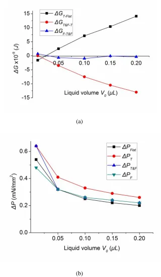
Figure 4.16. Kaydol on a Teflon® flat surface and a nylon fiber tip or body (rf = 0.143mm,
θfiber = 17°, θflat = 56°): (a) changes in free energy ΔG, and (b) Laplace pressure ΔP. ... 61
Figure 4.17. Water on a Teflon® flat surface and a glass fiber tip or body (rf = 0.145mm,
θfiber = 35°, θflat = 115°): (a) changes in free energy ΔG, and (b) Laplace pressure ΔP. ... 62
Figure 4.18. EG on a Teflon® flat surface and a glass fiber tip or body (rf = 0.145mm,
θfiber = 0°, θflat = 85°): (a) changes in free energy ΔG, and (b) Laplace pressure ΔP. ... 63
Figure 4.19. Kaydol on a Teflon® flat surface and a glass fiber tip or body (rf = 0.145mm,
θfiber = 0°, θflat =56°): (a) changes in free energy ΔG, and (b) Laplace pressure ΔP. ... 64
Figure 4.20. Water on a Teflon® flat surface and a PP fiber tip or body (rf = 0.1mm,
θfiber = 97°, θflat = 115°): (a) changes in free energy ΔG, and (b) Laplace pressure ΔP. ... 65
Figure 4.21. EG on a Teflon® flat surface and a PP fiber tip or body (rf = 0.1mm, θfiber = 69°,
θflat = 85°): (a) changes in free energy ΔG, and (b) Laplace pressure ΔP. ... 66
Figure 4.22. Kaydol on a Teflon® flat surface and a PP fiber tip or body (rf = 0.1mm,
θfiber = 69°, θflat = 85°): (a) changes in free energy ΔG, and (b) Laplace pressure ΔP. ... 67
Figure 4.23. Schematics of the motion of a liquid droplet on a fiber after vertically lifting the
fiber contacted with the droplet which rests on a flat surface. The droplet moves to: (a) the
fiber tip, (b) the tip and the body of fiber, and (c) the fiber body, ... 68
Figure 4.24. Transferring of a small volume of water (0.1 µL) resting on a Teflon® flat
surface to a nylon fiber (rf = 0.143mm) after vertically moving the fiber into contact with the
droplet and then lifting the fiber: (a) on flat surface, (b) on both flat surface and fiber, and
(c) on fiber tip. ... 69
Figure 4.25. Transferring of a large volume of water (2.0 µL) resting on a Teflon® flat surface
to a nylon fiber (rf = 0.143mm) after vertically moving the fiber into contact with the droplet
and then lifting the fiber: (a) on flat surface, (b) on both flat surface and fiber, and
(c) remaining on the flat surface. ... 69
Figure 4.26. Schematics of a liquid droplet on a fiber after horizontally moving the fiber into
the center of the droplet which rests on a flat surface. The droplet can: (a) reside on both the
flat surface and the fiber, (b) it can move onto the fiber body, (c) on the tip and the body of
Figure 4.27. ΔG of water on a Teflon® flat surface and a nylon fiber (θfiber = 72°, θflat = 115°):
(a) rf = 0.143mm, and (b) rf = 0.288mm. ... 73
Figure 4.28. ΔG of EG on a Teflon® flat surface and a nylon fiber (θfiber = 42°, θflat = 85°):
(a) rf = 0.143mm, and (b) rf = 0.288mm. ... 74
Figure 4.29. ΔG of Kaydol on a Teflon® flat surface and a nylon fiber (θfiber = 17°, θflat = 56°):
(a) rf = 0.143mm, and (b) rf = 0.288mm. ... 75
Figure 4.30. ΔG of water on a Teflon® flat surface and a glass fiber (θfiber = 35°, θflat = 115°):
(a) rf = 0.145mm, and (b) rf = 0.271mm. ... 76
Figure 4.31. ΔG of EG on a Teflon® flat surface and a glass fiber (θfiber = 0°, θflat = 85°):
(a) rf = 0.145mm, and (b) rf = 0.271mm. ... 77
Figure 4.32. ΔG of Kaydol on a Teflon® flat surface and a glass fiber (θfiber = 0°, θflat = 56°):
(a) rf = 0.145mm, and (b) rf = 0.271mm. ... 78
Figure 4.33. ΔG of EG on a Teflon® flat surface and a PP fiber (θfiber = 69°, θflat = 85°):
(a) rf = 0.1mm, and (b) rf = 0.19mm. ... 79
Figure 4.34. ΔG of Kaydol on a Teflon® flat surface and a PP fiber (θfiber = 29°, θflat = 56°):
(a) rf = 0.1mm, and (b) rf = 0.19mm. ... 80
Figure 4.35. 2.0 µL and 4.0 µL water on a Teflon® flat surface and a nylon fiber
(rf = 0.143mm) after horizontally moving the nylon fiber into the droplet. ... 82
Figure 4.36. 2.0 µL and 4.0 µL Kaydol on a Teflon® flat surface and a nylon fiber
(rf = 0.143mm) after horizontally moving the nylon fiber into the droplet. ... 82
Figure 4.37. 2.0 µL and 4.0 µL water on a Teflon® flat surface and a glass fiber
(rf = 0.145mm) after horizontally moving the nylon fiber into the droplet. ... 82
Figure 4.38. 2.0 µL and 4.0 µL Kaydol on a Teflon® flat surface and a glass fiber
(rf = 0.145mm) after horizontally moving the nylon fiber into the droplet. ... 83
Figure 4.39. 2.0 µL and 4.0 µL EG on a Teflon® flat surface and a PP fiber (rf = 0.1mm)
after horizontally moving the nylon fiber into the droplet. ... 83
(a) rf = 0.143mm, and (b) rf = 0.288mm. ... 84
Figure 4.42. ΔG of EG on a PET flat surface and a nylon fiber (θfiber = 42°, θflat = 47°):
(a) rf = 0.143mm, and (b) rf = 0.288mm. ... 85
Figure 4.43. ΔG of water on a PET flat surface and a glass fiber (θfiber = 35°, θflat = 72°):
(a) rf = 0.145mm, and (b) rf = 0.271mm. ... 86
Figure 4.44. ΔG of EG on a PET flat s surface and a glass fiber (θfiber = 0°, θflat = 47°):
(a) rf = 0.145mm, and (b) rf = 0.271mm. ... 87
Figure 4.45. ΔG of EG on a PET flat surface and a PP fiber (θfiber = 69°, θflat = 47°):
(a) rf = 0.1mm, and (b) rf = 0.19mm. ... 88
Figure 4.46. Water on both PET flat surface and nylon fiber (rf = 0.143mm) after horizontally
moving the nylon fiber into the droplet: (a) 2.0 µL, and (b) 4.0 µL. ... 89
Figure 4.47. EG on both PET flat surface and nylon fiber (rf = 0.143mm) after horizontally
moving the nylon fiber into the droplet: (a) 2.0 µL, and (b) 4.0 µL. ... 89
Figure 4.48. Water on both PET flat surface and glass fiber (rf = 0.145mm) after horizontally
moving the nylon fiber into the droplet: (a) 2.0 µL, and (b) 4.0 µL. ... 90
Figure 4.49. EG on both PET flat surface and glass fiber (rf = 0.145mm) after horizontally
moving the nylon fiber into the droplet: (a) 2.0 µL, and (b) 4.0 µL. ... 90
Figure 4.50. EG on both PET flat surface and PP fiber (rf = 0.15mm) after horizontally
moving the PP fiber into the droplet: (a) 2.0 µL, and (b) 4.0 µL. ... 91
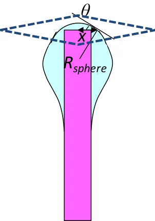
Figure 4.51. Schematics of a drop on a fiber with increasing the drop volume: (a) on the tip,
(b) on the tip and the body of fiber, (c) on both tip and fiber and touching flat surface, and
(d) on the flat surface and fiber combined system. ... 92
Figure 4.52. Schematics of a drop motion: (a) on the middle of the fiber, (b) and (c) on the
fiber and connected with the flat surface ... 93
Figure 4.53. Schematics of a drop when the ideal length of a drop (L) is longer than the fiber
height (hf): (a) a drop is on the tip and the body of fiber, and (b) a drop is on the fiber. ... 94
Figure 4.54. The critical fiber height (hC-T&F) of different liquid on nylon fiber:
(a) rf = 0.143mm, and (b) rf = 0.288mm ... 97
and (b) rf = 0.19mm. ... 98
Figure 4.56. The critical fiber height (hC-T&F) of liquid on different fiber (rf = 0.19mm):
(a) EG and (b) Kaydol. ... 99
Chapter 1 Introduction
A surface having a water contact angle greater than 150o and a very low roll-off angle is
called a superhydrophobic surface.1, 2High contact angles can be obtained by combined
treatments with low surface tension chemical agents and increasing surface roughness. The
roll-off angle depends on the drop size3 and the contact angle hysteresis, which is the
difference between the advancing and receding contact angles.4 Self-cleaning is so termed as
water easily rolls off a superhydrophobic surface taking away dirt. It would be beneficial if
similar “superoleophobic” materials existed. Compared with water, oils, such as vegetable oil
and most machine oils, have lower surface tension and more easily wet solid surfaces.
Superoleophobicity is commonly desired for clothing and carpets, which are easily
contaminated by oil but are not easy to clean.
The idea of superhydrophobicity was introduced six decades ago by A. Cassie working for
the British Council of the Wool Industries.5 Since then superhydrophobic treatments have
been studied in both academia and industry. Among these studies, mimics of the
superhydrophobic plant leaves have recently received more attention. There are two different
types of water-repellent plant leaves exemplified by: Lotus leaves and Lady’s Mantle leaves.
Lotus leaves have hydrophobic cuticles and protuberances which provide high surface
roughness, while Lady’s Mantle leaves have hydrophilic hairs on their less hydrophilic
surface. The term “Lotus effect” is used for surfaces which have water repellency via either
Compared with reports of superhydrophobic surfaces, reports of superoleophobic surfaces
are extremely rare. However, Lady’s Mantle leaves provide a clue for designing a
superoleophobic surface using oleophilic fibers and a less oleophilic surface since the leaves
are superhydrophobic although covered by hydrophilic hairs.
It is known that a liquid droplet resting on a solid surface has a Laplace pressure, which is the
pressure difference caused by the interfacial surface tension between the liquid and vapor.
For a static droplet, the Laplace pressure should be the same at each point of the liquid-vapor
interface; otherwise the pressure difference will change the shape of the drop or even move it
when the force caused by Laplace pressure difference can overcome resistive forces. On a
cylindrical fiber, the Laplace pressure is constant within the drop based on Carroll’s
equations6, but decreases with increasing fiber radius7. This suggests that a droplet will have
a decreasing Laplace pressure on a conical fiber as the fiber radius increases. The difference
of the Laplace pressure varied by the change of fiber radius may provide a force which drives
the droplet to move along the fiber.
The background for this research includes the wetting behavior of liquids on solid surfaces,
e.g. smooth flat surface, rough surfaces and fibers; the influence of fiber surface morphology
in liquid spreading; the Laplace pressure and the system free energy of droplets on solid
1) investigate conditions required for liquids transferring between a flat smooth surface and
fibers;
2) explore prerequisites for spontaneous movement of liquids along fibers; and
3) provide theoretical and experimental analysis of wetting a single fiber as a model
Chapter 2 Literature Review
2.1. Introduction
Superhydrophobic treatments have been studied in both academia and industry due to their
water repellency. Lotus leaves have hydrophobic cuticles and protuberances which provide
high surface roughness as shown in Figure 2.1.a. Nakajima et al. obtained superhydrophobic
films by coating a fluoroalkyl silane on a substrate.8 Michielsen and Lee designed and
prepared superhydrophobic surfaces using woven structures and flocked surfaces.9, 10 Zhu et
al. prepared a superhydrophobic surface by electrospinning a hydrophilic material,
poly(hydroxybutyrate-co-hydroxyvalerate).11 Zhai et al. found that superhydrophobic
behavior of the lotus leaf structure can be achieved by creating a semifluorinated silane
coated polyelectrolyte multilayer surface.12
Lotus leaf
Water drop (a)
Lady’s Mantle leaf Water drop (b)
mimicking the structure of Lady’s Mantle leaves.13 However, experiments have not
successfully mimicked the Lady’s Mantle leaves to produce superhydrophobic surfaces.
Production of superoleophobic surfaces resisting wetting with oil, which has much lower
surface tension, are extremely rare. Research to provide theoretical and experimental
evidence for model superoleophobic surfaces is needed.
Research review
Tuteja, Zimmermann, and Cao created superoleophobic surfaces by combining chemical
composition, roughened texture and surface curvature.15-17 Cohen et al. pointed out that
materials could be oil repellent with proper combination of re-entrant curvature and suitable
alteration of the surface energy.15, 18 Brewer et al. suggested that fluoropolymer fiber coated
materials could provide low surface tension liquid repellent properties to textiles.19 Cao et al.
demonstrated that porous Si films fabricated by a convenient gold assisted electrodeless
etching process would produce a superoleophobic surface on an intrinsically oleophilic
self-assembled monolayer coated Si surface.20 Steele et al. obtained a superoleophobic
surface on large and flexible surfaces, by spraying an emulsion of ZnO nanoparticles and
waterborne perfluoroacrylic polymer.21 Yan et al. created a surface on which salad oil
exhibited a 130° contact angle by coating fluorinated alkylsilane on a needle-like surface of
polyalkyppyrrole films. The geometrical factor of the film did not change during coating.22
Hsieh et al. found that rough surfaces coated with titanium dioxide nanoparticles and
perfluoroalkyl methacrylic copolymer could achieve contact angles as high as 144° for
dodecane (γLV = 25 mN/m) wetting are rare.
Patent review
Reihs et al. invented a method for producing a superoleophobic surface on an aluminum base
by anodized/anodic oxidation. They created a superoleophobic surface which had high liquid
contact angle and low roll-off angle by combining this treatment with low surface tension
chemical application. 24 They also developed water-repellent and oil-repellent surfaces using
an ultraviolet laser to obtain very high number of pores per surface area. First they coated
surface with an oil-repellent agent which was dissolved and freely moveable, and then coated
a the material with a second cover (outer surface). Through the pores created by ultraviolet
illumination the oil-repellent agents could diffuse to the outer surface to create an outer
coating which had an n-decane contact angle larger than 90°.25 Lamon et al. presented an
invention to obtain an oleophobic filtration medium including polymeric membranes and
other substrates that are coated with polymerized substituted or unsubstituted para-xylene.26
Yamaguchi et al. invented a method of preparing a water and oil repellent treatment of
textiles. The water and oil repellent agent comprises at least one fluorine-containing
compound and it also has a cationic emulsifier and a salt.27
Understanding wetting behavior is helpful to mimic the Lotus effect, because the
surface and fibers are introduced, and the possibility of droplet spontaneously moving from
one place to another is discussed.
2.2. Contact angle and wetting behavior
The characterization of surface tensions between the interacting solid and liquid is the key to
understanding the wetting behaviors of solid materials.15, 18 It is difficult to directly measure
the surface energy of solids but easy to obtain the contact angles of liquid on solid surfaces.
Therefore, contact angles between liquid with a known surface tension and a solid are
measured for the evaluation of surface characteristics such as surface energy and wetting
behavior. The relationship between the surface tensions and contact angle is given by
Young’s equation:28
c o s
S V S L
e L V
(2.1)
where γSV, γSL, and γLVare the interfacial surface tension between solid-vapor, solid-liquid and
liquid-vapor, respectively (Figure 2.2). Young’s equation is only applicable to flat smooth
surfaces, and the system should be at equilibrium. When θe for a test liquid is larger than 20°,
it is assumed that γSV = γS and γLV = γL.29 Equation (2.1) can be reformulated as:
c o s
S S L
e L
(2.2)
According to Fowkes30 and Lee31, when only dispersion interactions are present the
2
( )
L W L W L W
S L S L
(2.3)
ө
e
SL
SV
LV
Figure 2.2. Liquid droplet on flat surface.
Wetting behavior and apparent contact angle are related with surface structure.32 Since
Young’s equation is only appropriate for a flat smooth surface, other approaches are proposed
to express the contact angle of liquid on a rough surface.33, 34 There are two popular models
when the surface is roughened: Wenzel model and Cassie-Baxter model.
(a)
( b )
Figure 2.3. Liquid droplet on a rough surface: (a) Wenzel model, and (b) Cassie-Baxter
model.
be calculated.35 According to Wenzel theory, if liquid completely wets a solid rough surface
(Figure 2.3.a) the apparent contact angle (θrW) between liquid and the rough surface can be
described as follows:
e W
r r
cos
cos (2.4)
where r is the ratio of the total true wetted area of a rough surface to the area beneath the
drop obtained by projecting the drop onto a plane, and θe is the equilibrium Young contact
angle on a smooth surface of the same material. r is greater than or equal to 1, because the
total area of a rough surface must be greater than or equal to the projected area beneath it.
The Wenzel model describes two different behaviors: in the case of θe < 90⁰, liquid sinks into
and contacts with the rough surface θrW ~ 0; in the other case of θe > 90⁰, cosθrW goes
toward -1 and θrW approaches 180°. The behaviors suggest that with increasing roughness of
a hydrophilic surface (θe < 90⁰) its hydrophilicity improves; while the hydrophobicity
becomes better when the roughness of hydrophobic surface (θe > 90⁰) increased.
Cassie and Baxter extended the Wenzel model to porous surfaces (Figure 2.3.b). In the
Cassie-Baxter model, liquid sits on top of a composite surface consisting of solid surface and
air, and it does not fill the cavities. Cassie and Baxter suggested the following equation in
194436
2 1cos
cos rCB f e f (2.5)
where area projected liquid th contact wi in area 1 f , area projected air th contact wi in area 2 f ,
contact with a liquid.
The original Cassie-Baxter equation is often approximated by the following equation.37, 38
cos 1 1
cos rCB S e
(2.6)
where ϕS is the ratio of the rough surface area in contact with liquid to the projected area
covered by the liquid. Since ϕS ≤ 1, cosθrCB is less than or equal to cosθe, which means θrCB
is always greater than or equal to θe. Even though Equation (2.6) is used today, it is only
valid when liquid is in contact with a flat, porous surface. For most rough surfaces, the
original form, Equation (2.5), should be applied instead.9
Based on Equations (2.1 – 2.6) it is clear that a water or oil repellent surface which is
roughened and has low surface energy could be produced through the process of chemical
2.3. Liquid on solid surface
Whether liquid wets a flat solid surface or not depends on the spreading coefficient S which
is described as S = γSV - γSL - γLV. The increased liquid-vapor surface energy should be
balanced by a gain of interfacial energy at the solid-liquid and solid-vapor surfaces if liquid
spreads spontaneously along solid surface.
2.3.1. Liquid connected with reservoir on a solid surface
On a flat surface
As shown in Figure 2.4.a, the original position of a liquid on a flat surface is O. If the liquid
can spread it will pass position B. The free energy of a liquid on area AOB is G1 before
spreading and G2 after spreading. The energy difference of area OB before and after
spreading is ∆G = G2 - G1.
OB SV A
G1 (2.7)
2 L V O B S L O B
G A A (2.8)
OB OB
SV SL
LV A SA
G
( ) (2.9)
It is well known that a system always prefers the lower energy state. Therefore, whether the
liquid can spontaneously spread on a flat surface or not depends on state of the interfacial
free energy. According to Equation (2.9) if S < 0, ∆G is positive and the liquid cannot spread
O B
AOB
O B
2rf
x0
(a) (b)
Figure 2.4. Schematics of spreading of a liquid contacted with a huge reservoir: (a) on a flat
smooth surface, and (b) on a cylinder. x0 is the liquid film thickness on cylinder. O and B are
the positions before and after spreading, respectively.
On a cylinder
The spreading of liquid on a smooth cylinder is different from a flat surface as shown in
Figure 2.4.b. Interfacial free energy before spreading G1 and after spreading G2 for unit
spreading length can be represented as:
2 1 SV rf
G (2.10)
2 0 2
2 r (r x )
G SL f LV f (2.11)
Because the increased liquid-vapor interfacial surface area (radius rf + x0) is larger than
those of solid-liquid (radius rf) for liquid spreading on cylinder surface, the energy difference
of liquid before and after spreading on cylinder, ∆G = G2 - G1, will be negative only when
free energy of the thin liquid film on fiber G is given as:
1 2 3
G G G G (2.12)
where G1 is the excess liquid air interfacial energy per unit volume due to cylindrical
geometry, G2 is the energy due to the spreading term, G3 is caused by long range forces, and
these three energies can be given as:
1 0 2 2 L V f G x r
(2.13)
2 2 0 0 2 2 f f S r G
x x r
(2.14)
2
3 2 2
0( 0 2 0 )
L V f
f
a r G
x x x r
(2.15)
where x0is the equilibrium film thickness, a is a molecular size and rf is the cylinder radius.
The critical spreading SC is derived from two conditions: the equality of free energy between
a uniform thin liquid film and a droplet (G = 0) and the minimum of free energy of a thin
liquid film (dG / dx0 = 0). Therefore, based on Equations (2.12) – (2.15), SC can be derived as
following:
2 3
3
( ) 2
C L V
f
a S
r
(2.16)
2.3.2. Finite liquid droplet on a solid surface
On a flat surface
spherical cap and flat uniform film forms, respectively. The relationship between free energy,
surface tension and interfacial surface area can be expressed as:
) (
1 LV ALV SL ASL SV AS ASL
G (2.17)
S SL S
LV A A
G2 (2.18)
where ALV and ASL are interfacial surface areas between the liquid and the vapor and the solid
and the liquid, respectively. The liquid-vapor and solid-liquid interfacial surface areas are
equal when the liquid exists in the form of a film and both are expressed with solid surface
area AS. Based on Equations (2.17) and (2.18), the energy difference ∆G between the liquid
drop G1 and the film G2 is
2 1 L V( S L V) ( S L S V ) ( S S L)
G G G A A A A
(2.19)
In the case of a spherical cap, the entire solid surface area AS is much larger than the
solid-liquid interfacial surface area ALV, (AS - ALV ≈ AS), and AS is also much larger than the
liquid-vapor interfacial surface area ASL (AS - ASL ≈ AS); therefore Equation (2.19) can be
simplified to
S S
SV SL
LV A SA
G
( ) (2.20)
The final form taken by a liquid on a solid depends on spreading coefficientS . Liquid cannot
SL SV LV G1 ALV
ASL AS
G2
AS
(a) (b)
Figure 2.5. Schematics of a liquid drop on a flat smooth solid surface: (a) before
spreading-spherical cap, and (b) after spreading-flat uniform film. The total flat surface areas
AS in (a) and (b) are same.
On a cylinder
Figure 2.6 presents the forms of liquid drops before and after spreading on a cylinder in
which AS is the total cylinder surface area, and ALV and ASL are liquid-vapor interfacial
contact area and solid-liquid interfacial contact area. Subscripts 1 and 2 represent the states
of the liquid just after dropping it on the cylinder and after forming undulating drop,
respectively. As always G1 and G2 are the total free energy before and after spreading. They
can be written:
)
( 1
1 1
1 LV ALV SLASL SV AS ASL
G (2.21)
)
( 2
2 2
2 LV ALV SL ASL SV AS ASL
G (2.22)
Therefore the interfacial free energy difference ∆G between state (Figure 2.6.a) and (Figure
2.6.b) is
) )(
( )
( 2 1 2 1
1
2
Since cosθe = (γSV - γSL ) / γLV, Equation (2.23) can be rewritten as
LV LV SL SL e
LV A A A A
G ( 2 1)( 2 1)cos
(2.24)
ALV-2 is greater than ALV-1 because a sphere has the smallest surface area among all shapes.
Since liquid is spreading along the cylinder to form an unduloid shape, the solid-liquid
contact area will increase for a drop transforming its shape from a spherical shape
to undulating shape (ALV-2 > ALV-1). According to Equation (2.24), when
cosθe = (ALV-2 - ALV-1) / ( ASL-2 - ASL-1), ∆G is negative and a liquid drop will form an
undulating shape on the cylinder. This verifies the phenomenon that liquid drop would be
asymmetric on hydrophobic or oleophobic cylinder surface, because the asymmetric system
has lower interfacial surface energy compared to a symmetric undulating shape. This also
proves the phenomenon that liquid shape is symmetric on hydrophilic or oleophilic smooth
cylinder without the influence of external forces such as gravity.
G
12
r
fA
LV-1A
SA
SL-1G
2l
2
r
fA
SA
SL-2A
LV-2(a) (b)
Figure 2.6. Schematics of a liquid drop on a cylinder: (a) before spreading, and (b) after
No matter whether a drop on a solid surface is connected to a liquid reservoir or a liquid
droplet is dropped on the surface, liquid cannot spread along the solid surface and completely
wet if the spreading coefficient is negative for flat smooth surface or the coefficient is smaller
than the critical value for cylinder. To avoid liquid spreading, reducing surface tension of
solid surface by chemical modification is a potential solution.
2.3.3. Liquid on cylinder pulled out from reservoir
It is well known that if a cylinder is pulled out of a liquid reservoir very slowly, the only
liquid transferred is a spherical drop hanging on the end of the cylinder. If the pulling out
velocity is very large, there is not enough time for liquid to return to the reservoir. However,
sometimes the thin film will form undulating drops. Therefore there could be two final forms
for the case of quickly pulling a cylinder out of a reservoir: flat uniform film and undulating
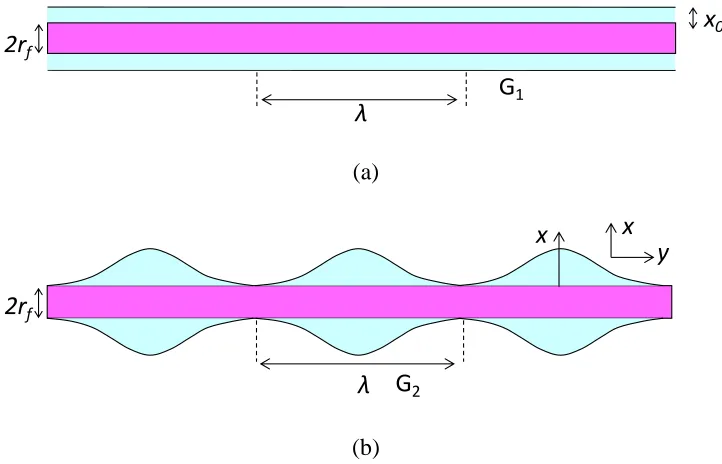
drops. The two possible forms are presented in Figure 2.7 where rf is radius of cylinder, x0 is
liquid film thickness, x is thickness of undulating drop, and λ is wavelength of the undulation.
In Figure 2.7, G1 and G2 are the interfacial free energy per wavelength of liquid-vapor in the
form of flat film and undulating drop, respectively. ∆G = G2 - G1 is the free energy difference
of the liquid which exists in the above two forms and they can be described as:
rf x LV
G1 2 0 (2.25)
r x
dyG f LV
0
2 2 (2.26)
LV f LV
f x dy r x
r
G 2 ( ) 2 ( 0)
0
x0 2rf
λ
G1
(a)
x
λ
x y
λ 2rf
G2
(b)
Figure 2.7. Schematics of liquid on a cylinder pulled out from a reservoir: (a) flat uniform
film, and (b) undulating drop.
The surface area of undulating shape ∫ λ02π(rf + x) dy can be calculated according to the
Rayleigh instability.6, 42 According to Equation (2.27), ∆G is negative when λ is greater than
2π(rf + x0), and liquid on cylinder becomes undulating. A flat liquid film will exist when the
film length is shorter than 2π(rf + x0), because the surface energy of the film is lower than the
undulating drop at this length range. Thus for long films, the film will break up into
undulating drops. The same result should occur if liquid vapor condenses on the cylinder.
the pressure difference sustained across the interface between a liquid and a vapor, and is
given by the Young-Laplace Equation (2.28)
K R R
P LV
2 1 1 1
(2.28)
where K is constant, R1 = xcosecϕ and R2 = dϕ / ds are the principal radii of curvature and s
is the arc length of drop shape. The Laplace pressure at each point of the interface between
liquid and vapor should be the same if the drop is static on a solid surface; otherwise the
force caused by a difference in the Laplace pressure will change the drop shape.
2.4.1. Laplace pressure of liquid on flat surface
Liquid forms a spherical cap on a solid flat surface as shown in Figure 2.8, where R0 is the
radius of the sphere. Since the principal radii of curvature of the sphere are equal to its radius
(R1 = R2 = R0), the Young-Laplace Equation (2.28) can be transformed to:
0 2 1 2 ) 1 1 ( R R R
P LV LV
(2.29)
31 3 3
1
0
0 2 3cos cos
3 V
R (2.30)
where θ= θe.
R0
θ
e O R1s
2.4.2. Laplace pressure of liquid on fiber tip
For liquid on a fiber tip when the liquid volume is small and the contact line is away from the
edge as shown in Figure 2.9.a, the drop is a part of sphere because the drop rests on a flat
surface. The Laplace pressure of this drop can be obtained by Equation (2.29) and (2.30).
O
R
0θ
2
r
f
O R
0θ
2
r
f(a) (b)
Figure 2.9. Schematics of the principal radii of curvatures of a liquid drop on fiber tip:
(a) drop contact line away from the edge of fiber tip, and (b) drop pinning at the edge.
As the liquid volume grows, the drop radius grows until the drop completely covers the tip of
the fiber. As still more liquid is added, the apparent contact angle (θ) increases. At this point,
the contact line between the drop edge and the fiber is pinned at the edge of the fiber but the
side of the fiber, the drop collapses and encapsulates the tip. Before the collapse, the Laplace
pressure of the drop can be expressed in Equation (2.29) and the principal radius of curvature
R0 is a function of drop volume V0.
2.4.3. Laplace pressure of liquid on cylindrical fiber
A drop will show an undulating shape on a hydrophilic cylinder instead of a spherical cap
shape on a flat surface due to the morphology of cylinder. It is easy to see that an undulating
shape has both convex and concave parts seperated by an inflection point. The principal
radius of curvature R2 is different for the convex part of the drop than for the concave part as
shown in Figure 2.10.a and 2.10.b.
2rf
x y
y
Φ
x R2
O
s R1
(a)
2rf
x y
y
Φ
R1 x R2
O
s 2h
l
(b)
Figure 2.10. Schematics of principal radii of curvatures of a liquid drop on a cylinder: (a) on
Carroll derived the Young-Laplace Equation (2.28) for an undulating drop on a cylinder in 1976:6 1 cos 2 2 n n r P fiber f LV (2.31)
where rf is radius of fiber, n = h / rf and h is the maximum height of drop derived by rf and
drop volume V0, and the subscript fiber refers to “on the fiber” as shown in Figure 2.10.b. It
is easy to see that the Laplace pressure ∆P of a liquid on a cylinder is determined by the
liquid surface tension, the radius of the cylinder and the liquid volume.
The liquid-vapor surface area ALV-fiber and solid-liquid surface area ASL-fiber of a droplet on the
fiber body have been given by Carroll6
) , ( ) (
4 r2n a n E k
ALVfiber f (2.32)
( , ) ( , )
4 r2 aF k nE k
ASLfiber f (2.33)
where F(φ, k) and E(φ, k) are the elliptical integrals of the first and second kind, respectively.
a = (ncosθfiber - 1) / (n - cosθfiber), k2 = 1 – a 2/ n2 and sin2φ = (1 / k2)(1-1 / n2). In addition, n is
constrained by the droplet volume, V0, which for the droplet on a fiber body is given by
Carroll6 as:
3 2
2 2 2 0 .5
0 2
3
2 1 1
( 2 3 2 ) ( , ) ( , ) ( )
3 1
2 ( , ) ( , )
f
f
r n
V n a a n n E k a F k
n a
angle θfiber could be obtained from the measurement of drop shape parameter h with the
limitation that the drop should be symmetrical along the cylinder axis direction which
requires θfiber < 60⁰. By observing the shape of a droplet on cylindrical fiber Yamaki et al.
provided a method to obtain liquid contact angle on fiber, and the predicted angle was very
close to the observed one.47 Song et al. presented a method to calculate the static contact
angle according to the geometry of droplet on a cylinder. The method could provide an
accurate contact angle to within 5°.48 Wagner could obtain highly accurate contact angle by
calculating dimensions of droplet on fiber. 49
2.4.4. Laplace pressure of liquid on conical fiber
Laplace pressure influences the shape of a drop and a difference in pressure creates a driving
force which can change the shape and even force a drop to move. The Laplace pressure ∆P
will decrease with an increase in liquid volume V0 since the radius of the drop increases
(Equations (2.29) and (2.31)). This explains why a small drop of liquid will flow into a larger
one if these two drops are connected with each other. The Laplace pressure of a droplet varies
on solid surfaces which have different surface tensions since the different solid-liquid surface
tensions cause a difference in the contact angles and thus changes the radii of curvature. Thus,
a droplet could move from lower surface tension area to a higher one, which results in the
motion of a drop from hydrophobic areas to hydrophilic areas.A drop may also travel along a
cylinder which has proper surface roughness caused by radius variation, because according to
Equation (2.31) the Laplace pressure increases if the radius of cylinder decreases provided n
a liquid on a conical fiber whose radius increases from the tip to the base as shown in Figure
2.11. The Laplace pressure of a drop on the small radius section of the cone is larger than on
the larger radius region according to Equation (2.31). This suggests that a drop may move
along a fiber from smaller radius to a larger one, if gravity can be ignored.
y
x
2h
r
f1r
f22
α
Figure 2.11. Schematic of a liquid drop on a conical fiber. Radius of the cone increases from
the tip to base of the cone (marked as y direction), and a is the half-angle of the cone.
Besides showing the variation in radius, Figure 2.11 also indicates that the maximum
thickness of the drop h changes for different locations along the cone. Based on Equation
(2.31) the gradient of Laplace pressure difference of a drop on conical fiber along the cone
0 0 ) cos ( 2 2 2 V f e f LV V dy r h r h d dy P d
(2.35)
Equation (2.35) can be rewritten as:
0 0 2 cos cos 22 2 2 2 2
2 2 2 V f f e f e f f f LV V dy dr hr r h dy dh hr r h r h dy P d (2.36)
In the case of undulating drop on a thin hydrophilic cylinder, the maximum radius of the drop
R0 (R0 = h - rf) is much larger than rf; therefore h can be assumed to be a constant (h ≈ R0)
with constant liquid volume V0. When n >> 1, n - cosθe ≈ n - 1. Equation (2.36) can be
reformulated as:
0 0 0 2 0 20 ( )
tan 2 2 V f LV V f f LV
V dy r R
dr R r dy P d (2.37)
In the case of a very thin liquid film on a on a conical fiber (rf ≈ h), and Equation (2.36) can
be written as:
0 0 2 tan V f LV V r dy P
d
(2.38)
written as ∆P = 2γLV/ (h + rf) and the pressure difference along the cone in the direction of
increasing radius and at constant volume changed would be given by Equations (2.37) and
(2.38), respectively.
In Equation (2.37) and (2.38) α is the half-angle of the cone and the negative sign means the
Laplace pressure decreases in the direction that the radius of the cone increases. The driving
force caused by the pressure difference in the liquid would drive it to move if the force is
large enough to overcome the resistive forces. Liu et al. also pointed out that a liquid droplet
has the least potential energy on the base of a conical fiber compared to other locations on the
cone, which means the liquid droplet tends to move from conical fiber tip to its base.50
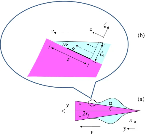
2.5. Motion of a droplet on a conical fiber
When a drop moves on a conical fiber, there are three forces working on it: driving force Fdriv,
gravitational force FG, and viscous force Fη. Dissipation occurs because of the friction of
relative motion caused by viscosity of liquid. Since the friction between gas and liquid
molecules and the friction between liquid molecules are negligible for low viscosity liquid,
2rf y v y x α (a) (b)
Figure 2.12. Schematics of a drop on a cone: (a) liquid moving on the cone, and (b) the
magnification of liquid wedge of the moving drop. The drop moves with an average velocity
v along cone axis in the direction of increasing radius (marked as y), and it moves along the
cone surface with an instantaneous velocity u(ξ).
Figure 2.12 presents the liquid wedge in steady state, and θ is the dynamic contact angle. The
velocity u(ξ) of liquid has a gradient along the liquid thickness because of viscosity of liquid.
Suppose the liquid moves at an average velocity along fiber axis (y direction). Then the
relationship between the instantaneous velocity u(ξ) along the cone surface and the average v
along the cone axiscan be written40, 51, 52 as:
2 0 1 3 1 cos 2 v u (2.39)
contact line between liquid and fiber in the liquid wedge (ξ0 = θz) as shown in Figure 2.12.b.
The viscous force over the wedge depth ξ0 is 3ηv / 2cosα where η is the liquid viscosity;
hence, the viscous force in the liquid wedge per unit length of the contact line can be
expressed as: cos 2 3 cos 2 3 max min vk dz z v f z z
(2.40)where k = ln(zmax / zmin), zmax and zmin are the maximum and minimum cutoff lengths and they
are zmax = (ρg / γLV)-0.5, and zmin ~ aθ-1 (ρ is liquid density, g is the gravitational acceleration,
and a is a molecular size). Therefore, the viscous force along fiber axis, which is the opposite
direction as the driving force caused by Laplace pressure gradient, is 3ηkv / 2θ.The total
viscous force Fη in the liquid wedge at radius rfof cone can be written as:
kv r f r
F f f
3 cos
2
(2.41)
The net driving force Fdriv can be obtained by integrating the Laplace pressure difference
times the area around the entire liquid surface.
P d r x
Fdriv
( f )2 (2.42)Based on Equation (2.37), Equation (2.42) can be reformed as:
dy R r r x F f LV f driv 2 0 2 ) ( tan 2 ) (
For rf << R0, 2γLV tanα / ( rf + R0)2has almost no change for a very thin cone, so dy r x R r F f f LV driv 2 2 0 ) ( ) ( tan 2
(2.44)
According Carroll’s equations, the relationship between dy and dx of a droplet on cylinder
fiber can be expressed as:
2
2 2 2 2 2
( ) ( )
f
f
x a h r d y
d x h x x a r
(2.45)
where a = (ncosθfiber - 1) / (n - cosθfiber), θfiber is the Young contact angle of the liquid on a flat
surface of the same material as the fiber.
It is well know that ∫π(x - rf)2dy is the liquid drop volume V0, so
0 2 0) ( tan 2 V R r F f LV driv
(2.46)
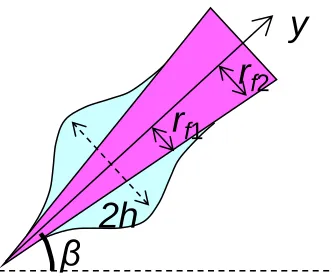
The gravitational force of liquid drop FG is
gV0sin
FG (2.47)
where ρ is the density of the liquid, g is the gravitational constant, β is the tilt angle with
y
β
2h
r
f1r
f2Figure 2.13. Schematic of a liquid drop on a titled conical fiber. Radius of the cone increases
from the tip to base of the cone (marked as y direction), and the cone is tilted at an angle β
with horizon direction.
For the case of drop moving spontaneously on a cone, the driving force should be equal or
greater than the resistive forces (gravitational force and viscous force): Fdriv ≥ FG+Fη;
therefore based on Equation (2.41), (2.46) and (2.47) the gradient of the cone, tanα, and the
average velocity of drop v can be expressed as:
0 2 0 0 2 ) ( ) 3 sin ( tan V R r v kr gV LV f f
(2.48)
f f LV kr V g R r v 3 sin ) ( tan 2 0 2 0
(2.49)
a drop moving on a planar surface, the drop on a fiber can sometimes form a global
macroscopic wedge with a dynamic contact angle θ which is close to the Young static contact
angle θe , instead of a local Hoffman wedge.7 When the dissipation is global and if the motion
does not affect the static shape of drop, the dynamic contact angle can be expressed with the
static angle: θ ~ (h - rf ) / l.52, 54
From Equation (2.49), it can be seen that the velocity of a drop has relationships with liquid
surface tension and volume, local radius and gradient of the cone. With an increase in the
gradient of a cone or in the liquid volume, the velocity of the drop should increase, and it
should decrease if the radius of the cone increases.
A Laplace pressure difference could provide the driving force to drive oil from an oleophobic
surface to an oleophilic surface. It also can cause liquid to move on the surface of a conical
fiber once the driving force overcomes the resistive forces. Hence, if the surface is
oleophobic, the cone attached to it is less oleophilic, and the gradient of the cone is large
enough, it is possible that oil could transfer from the tip to the base of the cone and stay there
without falling back. This may be the mechanism of Lady’s Mantle leaves which is super
liquid repellent.
2.6. Summary
In this chapter, the wetting behavior of flat surfaces and cylinders are introduced. The liquid
surfaces can be described by Young, Wenzel and Cassie-Baxter Equations (2.1, 2.4, and 2.5),
respectively.
Liquid spreads on flat smooth surfaces when the surface is connected with a liquid reservoir
or when just a small liquid drop is dropped on it if the spreading coefficient is positive. For a
cylinder, the coefficient must be greater than a critical value (S > SC) for the liquid to spread.
Usually either a symmetric undulating drop forms on a hydrophilic cylinder or an
asymmetric shape exists if the external force is not negligible and the static contact angle is
too large. The Laplace pressure of a liquid on a flat surface and on a cylinder was presented
as Equations (2.29) and (2.31).
The Laplace pressure should be same throughout a static liquid drop; otherwise the pressure
difference will force the drop to change shape or even move. The Laplace pressure of a drop
on a cylinder varies with changes of liquid volumeV0, wetting behavior θe or radius rf of the
cylinder. The drop can move once the driving force overcomes the resistive force such as
gravitational force and viscous force. Understanding the wetting behavior of solid surface
could provide clues to obtain superhydrophobic and superoleophobic surfaces.
Even though the contact angle and wetting behavior of roughened flat surfaces and cylinders
a droplet to move along a fiber can be obtained according to theoretical and experimental
research in this area. These conditions will provide useful information on approaching