Transactions,SMiRT-23
Manchester, United Kingdom - August 10-14, 2015
Division II, Paper ID 758 (inc. assigned division number from I to X)
ESTIMATION OF C(t) UNDER GENERAL ELASTIC-PLASTIC-CREEP
CONDITIONS
Han-Sang Lee1, Jin-Ho Je1, Kyung-Dong Bae1, Yun-Jae Kim1, Robert A. Ainsworth2, Peter J. Budden3, David W. Dean3, and Kamran Nikbin4
1Mechanical Engineering, Korea University, Republic of Korea 2Aerospace and Civil Engineering, The University of Manchester, UK 3EDF Energy, UK
4Mechanical Engineering, Imperial College, UK
ABSTRACT
This paper estimate time dependent C(t) integrals under elastic-plastic-creep conditions. Finite element (FE) transient creep analyses have been performed for Single-Edge-notched-Bend (SEB) specimen. The effect of the initial plasticity on transient creep is investigated by systematically varying the magnitude of the initial step-load. Both same stress exponent and different stress exponent in power-law creep and plasticity were considered to elastic-plastic-creep behaviour. For estimation of C(t) integrals, finite element analysis results were compared with formulas. This paper propose modified equation to predict C(t) integrals for the case of creep exponent different from plastic exponent.
INTRODUCTION
Estimates of creep crack growth are one input into life assessments of components operating at high temperature has been successfully correlated with the amplitude of the singular stress and strain fields at the crack tip (Riedel, 1987). For stationary cracks the variation with time, t, is usually denoted C(t). At the steady-state creep conditions (tȥ˳) or under widespread creep conditions, the notation C*is used for the value of C(t). These parameter are strictly valid only for stationary cracks, but they are also relevant to the practical situation of low crack growth (Ainsworth, 1982; Riedel, 1987; R5, 1998).
When the plastic zone is small, that is small scale yielding conditions, the crack tip stress fields at time
t=0 is characterised by the stress intensity factor, K. As tȥ,C(t) ~ K2/E’(n+1)tis singular. An estimation of C(t) was developed by simple interpolation (Riedel, 1987). Ainsworth and Budden (1990) refined by matching the near crack tip fields described by C(t). Under widespread plasticity, however, the approach based on Kcan invalidate. For widespread plasticity, Joch and Ainsworth (1992) presented the effect of plasticity on the magnitude of C(t) during the transition phases. The FE results support that C(t) is bounded as tȥ, and reduces with increasing level of plasticity for the case of equal plastic exponent (m) and creep exponent (n). Fujioka and Ainsworth (2000) also reported approximate expressions for m=n andm<n. Kim et al (2001) refinedC(t) estimation formula by changing value of creep exponent for m=n. This paper extends the approach of Ainsworth and Budden (1990) to estimating C(t) integral under elastic-plastic-creep conditions for SEB specimen, based on two-dimensional FE analyses. Both same stress exponent and different stress exponent in plasticity and creep were considered to elastic-plastic-creep behaviour.
FINITE ELEMENT ANALYSIS
23 Conference on Structural Mechanics in Reactor Technology Manchester, United Kingdom - August 10-14, 2015 Division II (include assigned division number from I to X)
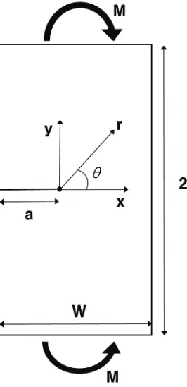
Figure 1. Specimen considered in this work, schematics: plane strain SEB.
One typical geometry was considered in this work: plane strain single-edge-notched bend (SEB) specimen, as depicted in Fig. 1. The specimen width, W, was taken to be W=50mm with the relative crack depth of a/W=0.5.
Material Properties
An isotropic elastic-plastic material was considered, characterized by the following power-law equation:
0.002
with and
m
e p o
o o
o o
m
E
E E
A E
s
s s
e e e ae a e
s s
s s
æ ö
= + = + ç ÷ = =
è ø
= +
(1)
where ƃe and ƃp denote elastic and plastic strain; A and m are material constants. For elastic properties, the following values were used: Young’s modulus E=200GPa and Poisson’s ratio Ɗ=0.3. For plastic properties, the yield strength Əo was assumed to be Əo=300MPa with two values of the strain hardening exponent, m=5 and 10.
For creep analyses, the material was assumed to follow power-law creep:
23rd Conference on Structural Mechanics in Reactor Technology
Manchester, United Kingdom - August 10-14, 2015 Division II (include assigned division number from I to X)
where B and n are material constants. Two values of the creep exponent n were considered, n=5 and 10. For the creep constant, the following values were assumed, B=3.2x10⁻¹⁵ for n=5 and B=3.2x10⁻²⁵ for n=10, but these choices do not affect the results as these are presented in a normalized manner.
Magnitude of initial step-load
The effect of the initial plasticity on transient creep is investigated by systematically varying the magnitude of the initial step-load. The geometry dependence of the load magnitude can be removed by normalising the load with respect to the plastic limit load per unit thickness (ML) of the cracked geometry, as given by Webster and Ainsworth (1987).
(
)
21.261
for SEB 2 3
L o
M = B W-a s
(3)
The ratio of the applied load to the limit load, Lr, given by:
ref r
L o
M L
M
s s
= =
(4)
For SEB specimen, three values of Lr are considered: Lr =0.5 corresponds to small-scale yielding; Lr =0.8 is associated with contained yielding conditions; Lr =1.0 is fully-plastic yielding conditions.
Finite element analysis
Elastic-plastic-creep FE analyses of SEB specimen were performed using ABAQUS (2013). A small geometry change continuum FE model was employed. To avoid problems associated with incompressibility, eight-noded plane strain element with reduced integration (CPE8R within ABAQUS) were used. Fig. 2 depict the FE mesh for SEB specimen. The number of elements and nodes in the FE meshes were about 4542 and 14055. The crack-tip was designed with collapsed elements, and a ring of wedge-shaped element was used in the crack-tip region. To calculate accurate C(t) integral even under transient creep conditions, sufficiently fine meshes were used at the crack tip. Validity of the crack-tip mesh design will be discussed later. With a sufficiently fine mesh, the value of C(t) was determined by simply taking the second contour value (Kim, 1999) from ABAQUS (note that C(t) is defined [Ainsworth and Budden (1990)] as the value on the limiting contour approaching the crack tip).
Mesh sensitivity
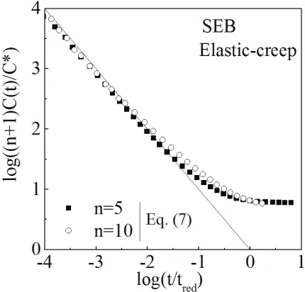
To ensure confidence in the mesh, the asymptotic behaviour of C(t) at very short times was evaluated. Elastic-creep FE analysis was performed for SEB specimen. At small times (tȥ), values of elastic-creep C(t) should approach (Riedel, 1987):
(
)
(
)
(
( )
)
2 1 2
0 ( )
1 1
K J
C t
n Et n t
n
-® =
+ +
(5)
23rd Conference on Structural Mechanics in Reactor Technology
Manchester, United Kingdom - August 10-14, 2015 Division II (include assigned division number from I to X)
( )
*
0
red
J t
C
=
(6)
Combining Eqs. (5) and (6) suggests at short times:
(
)
( )*log 1 log
red
C t t
n
t C
é ù
é ù
+ » ê ú
ê ú
ë û ë û
(7)
Figures 3 compare FE results with Eq. (7) suggesting that the FE mesh used in the present work can provide accurate C(t) values even at t/tred=10-4.
Figure 2. FE mesh used for SEB specimen in the present work
23rd Conference on Structural Mechanics in Reactor Technology
Manchester, United Kingdom - August 10-14, 2015 Division II (include assigned division number from I to X)
RESULTS
Reference Fields
For elastic-creep condition, Ehlers and Riedel (1981) proposed a simple approximation for C(t) as the sum of the short-term value of Eq. (5) and the long-term value (C*). With the definition in Eq. (8) this is:
( ) 1 1
1 1
* ( 1) ( 1)
red
t C t
C = + n+ t = + n+ t (8)
where Ɛ denotes the normalized time, defined by:
red
t t
t = (9)
Later Ainsworth and Budden (1990) proposed a slightly different form base on addition of short and long-them value of J:
(
)
(
)
1 1 1 ( )* 1 1
n n C t C t t + + + = + (10)
For elastic-plastic-creep conditions, Joch and Ainsworth (1992) proposed that the effects of initial plasticity on C(t) could be incorporated using a factor ϕ, defined for m=n by:
* 1
(0) AC BJ
f= - (11)
where J(0) denotes the elastic-plastic value of J at t=0, the material constants for plasticity and creep, A and B, are given in Eq. (1) and (2), respectively. An estimation formula for C(t) is then given by:
(
)
(
)
1 1 1 ( ) * 1 n n C t C t t f + + + =+ - (12)
In this work, new estimation formula for C(t) is proposed by changing values of factor ϕ, using crack-tip stress field. For changing values of factor ϕ, HRR fields (characterize elastic-plastic crack-tip stress fields, [Hutchinson, 1968; Rice and Rosengren, 1968]) and RR field (characterize steady state creep crack-tip stress fields, [Riedel and Rice, 1980]) are used. HRR fields and RR fields are given in Eq. (13) and (14).
1 1
0
(0)
( , ) : HRR field ( 0)
m yy
yy
o m o o
J
D m t
I r
s
s q
s a s e
+
=
é ù
= =ê ú =
ë û syyyy( ,( ,( ,q000) :) :
D m
D syy( ,( ,( ,( ,( ,( ,mq ) :) :
D m
D ( ,( ,m ) :
D m
D ( ,( ,( ,m (13)
23 Conference on Structural Mechanics in Reactor Technology Manchester, United Kingdom - August 10-14, 2015 Division II (include assigned division number from I to X)
1 1
0
*
( , ) : RR field ( )
n yy
yy
o n o o
C
E n t
I r
s
s q
s s e
+
=
é ù
= =ê ú ® ¥
ë û ssyyyy( ,( ,( ,( ,( ,qq 00) :) :) :
E syy( ,( ,( ,nq 00) :) :
E n
E syy( ,( ,( ,nq
E s nq
E n
E ê ú n
I r
E n
E n
E n
ëIII eorrrû
ê ú
ê ú
I r
I r
I r ssyyyyyy qq
E n
E yy n (14)
where E denote the normalized opening stress at the steady state creep condition; In, ssyyyyyy( ,( ,( ,( ,( ,( ,nqq=000)) are dimensionless function for a range of n.
There are process to make a new estimation formula for C(t). First, Eq. (12) raised to the power of 1/(n+1):
(
)
(
)
1 1 1 1 1 1 ( ) * 1 n n n C t C t t f + + + + é ù = ê ú ë û é + - ù ê ú ë û (15)then multiply Eq. (15) by Eq. (14):
(
)
(
)
1 1 0 1 1 1 1 ( ) ( , ) 1 n yy yyo n o o n
n E C t n I r s t s q
s s e
t f + = + + + é ù =ê ú = ë û é ù + -ê ú ë û 0
( , 0
yy
syy( ,( ,( ,q s ( ,( ,( ,( ,q 0 s ( ,( ,( ,( ,q
s q
=ê ú s q =
I r
ê ( ) ú
= =
= =
= =
ëIII o oo oo oo oo oo orrrû
ê ú
êIII rrrú ss qq (16)
Equation (16) denotes RR field at transient creep conditions. At small times (tȥ), values of Eq. (16) should approach D (Eq. 13). At steady state creep conditions (tȥ˳), values of Eq. (16) should approach E (Eq. 14). Therefore, Eq. (16) can be described given bellow:
(
)
(
)
1 1 0 1 1 1 1 1 ( ) ( , ) 1 1 n yy yyo n o o
n n n E C t n I r E D s t s q
s s e
t + = + + + + é ù =ê ú = ë û é ù æ æ ö ö ê + - - ç ÷ç ÷ú ç è ø ÷ ê è øú ë û 0
( , 0
yy
syy( ,( ,( ,q s ( ,( ,( ,( ,q 0 s ( ,( ,( ,q
s q
=ê ú s q =
I r
ê ( ) ú
= =
= =
= =
ëIII o oo oo oo oo oo orrrû
ê ú
ê ú
I r
I r
I r ss qq
(17)
Finally, Eq. (17) is divide by Eq. (14), then it raised to the power of (n+1):
(
)
(
)
1 1 1 1 ( )with ' 1
* 1 '
n n
n
C t E
C D t f t f + + + + æ ö = = - ç ÷ è ø
+ - (18)
Equation (18) is the new estimation formula for C(t) proposed in present work. If m=n, factor ϕ' in Eq. (18) can be described by:
(
)
*
' 1 0 ' 1
(0) AC BJ
f = - £f £ (19)
23rd Conference on Structural Mechanics in Reactor Technology
Manchester, United Kingdom - August 10-14, 2015 Division II (include assigned division number from I to X)
Elastic-plastic-creep FE results
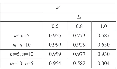
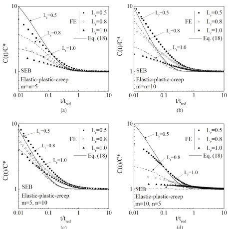
Elastic-plastic value of J-integral at t=0 (J(0)) and elastic-plastic-creep value of C-integral at steady state (C*) are determined from FE results. Determined values of J(0) and C* are presented in Table 1. Values of factors ϕ' in Eq. (18) are calculated using Eq. (13) and (14) with determined values of J(0) and C*. Calculated values of factor ϕ' are present in Table 2. The proposed estimation formula for C(t) (Eq. 18) are compare with the FE result in Fig. 4. Although the prediction is slightly non-conservative for the case
of m=10, n=5 with Lr=1.0, the predictions are, overall, conservative and satisfactory even mn. CONCLUSION
Finite element transient creep analyses have been performed for Single-Edge-notched-Bend specimen. Both elastic-creep and combined plastic and creep behaviour were considered. In the case of initial
plasticity, m=n and mn were analysed, where m and n are the plasticity and creep exponent, respectively. The full range between initial transient creep response and steady state conditions has been analysed for a range of initial load levels. Comparisons have been made between the computed C(t) integrals and the proposed estimation formula for C(t). It is concluded that proposed estimation formula provide improved agreement with the FE results. Moreover, these formula can be used to predict values of C(t), even if stress exponent is different from creep exponent (mn). Although this works were performed for one geometry, we believed that present results can provide insight on the estimation of C(t) under transient creep conditions.
Table 1: Values of J(0) and C* in Eq. (13) and (14) from FE results.
J(0) (MPaŘmm) C* (MPaŘmm/h)
Lr Lr
0.5 0.8 1.0 0.5 0.8 1.0
m=n=5 6.03 20.20 42.40 1.06 17.85 68.07 m=n=10 5.67 17.92 42.39 6.84 1203 14001 m=5, n=10 6.03 20.20 42.40 6.84 1203 14001 m=10, n=5 5.67 17.92 42.39 1.06 17.85 68.07
Table 2: Values of ϕ' in Eq. (18) at r/a=0.015. ϕ'
Lr
0.5 0.8 1.0
23rd Conference on Structural Mechanics in Reactor Technology
Manchester, United Kingdom - August 10-14, 2015 Division II (include assigned division number from I to X)
(a) (b)
(c) (d)
Figure 4. Variations of C(t)/C* for the case of elastic-plastic-creep with different values of Lr: (a) m=n=5, (b) m=n=10, (c) m=5, n=10, and (d) m=10, n=5.
NOMENCLATURE
a crack depth
W specimen width
A material constant for plasticity B material constant for creep
D normalized opening stress at time t=0 (HRR field)
E normalized opening stress at the steady state creep condition (RR field) C*, C(t) C-integral for steady state and transient creep conditions
23rd Conference on Structural Mechanics in Reactor Technology
Manchester, United Kingdom - August 10-14, 2015 Division II (include assigned division number from I to X)
E Young’s modulus
E’=E/(1-Ɗ) Young’s modulus for plane strain conditions J, J(0) J-integral and initial J value at time t=0 K linear elastic stress intensity factor
Lr parameter measuring the proximity to plastic collapse
m strain gardening exponent
n creep exponent
t time
tred redistribution time
ſ coefficient in the Ramberg-Osgood model
ƃ strain
ƃUHI reference strain
Ɛ normalized time, t/tred
Ə stress
ƏUHI reference stress
ƏR yield strength
ACKNOWLEDGEMENTS
This research was supported by National Research Foundation of Korea (NRF) funded by the Ministry of Science, ICT and Future Planning. (2013M2B2A9A03051295, 2013M2A7A1076396, NRF-2013M2B2B1075733)
REFERENCES
ABAQUS version 6. 13. (2013). User’s manual, Inc. and Dassault Systems.
Ainsworth, R. A. (1982). “Some observations on creep crack growth,” International Journal of Fracture Mechanics, 20, 147-159.
Ainsworth, R. A. and Budden, P. J. (1990). “Crack tip fields under non-steady creep conditions – I. Estimates of the amplitudes of the fields,” Fatigue & Fracture of Engineering Materials & Structures, 13, 263-276.
British Energy Generation Ltd. (1998). An assessment procedure for the high temperature response of structures., R5 Issue 2 Revision 2.
Ehlers, R. and Riedel, H. (1981), “A finite element analysis of creep deformation in a specimen containing a macroscopic crack,” ICF5, France, 2, 691-708
Fujioka, T. and Ainsworth, R. A. (2000). “A simplified estimation method of a crack propagation parameter in non-steady creep,” ASME PVP conference, Seattle, 412, 75-81.
Hutchinson, J.W. (1968). “Singular Behavior at the End of a Tensile crack Tip in a Hardening Material.” Journal of the Mechanics and Physics of Solids, 16, 13-31.
Joch, J. and Ainsworth, R. A. (1992). “The Effect of geometry on the development of creep singular fields for defects under step-load controlled loading,” Fatigue & Fracture of Engineering Materials & Structures, 15, 229-240.
23rd Conference on Structural Mechanics in Reactor Technology
Manchester, United Kingdom - August 10-14, 2015 Division II (include assigned division number from I to X)
Kim, Y. J., Dean, D. W. and Budden, P. J. (2001). “Finite element analysis to assess the effect of initial plasticity on transient creep for defects under mechanical loading,” International Journal of Pressure Vessels and Piping, 78, 1021-1029.
Rice, J.R. and Rosengren, G.F. (1968). “Plane Strain Deformation near a Crack Tip in a Power-Law Hardening Material.” Journal of the Mechanics and Physics of Solids, 16, 1-12.
Riedel, H. and Rice, J.R. (1980). “Tensile Cracks in Creeping Solids.” American Society for Testing and Materials, Philadelphia, 112-130.
Riedel, H. (1987). Fracture at high temperature, Berlin, Springer-Verlag.