Performance Analysis of Small Scale Wind Turbine at
Various Angles of Attack With Different Velocities
Vivek S Patel, Arun Walikar, Veeresh G.
Gunjalli
IV Year Student, IV Year Student, Assistant Professor, Department of Mechanical Engg., K.L.E. Institute of Technology, Hubli, Karnataka,
India
[email protected] [email protected]
Dr. Madhukeshwara N
Professor, Department of Mechanical Engg., Jain Institute of Technology, Davanagere, Karnataka,
India,
Abstract-For applications of an effective energy resource in future, the limitations of fossil fuels are clear and the security of alternate energy sources is an important subject. Among others, wind energy technologies have been developed and are about to play a major role on new energy field. It is observed even in many villages power cut off for entire night. Here an attempt is made to develop the cost economical and effective wind turbine which can fulfil the basic needs such as lightening of village houses. In the present work a small scale wind turbine with five blades coupled to PMMG motor is developed. Experimentation is conducted on turbine at various angles of attacks with different wind velocities and the results are tabulated. It is observed that maximum power is developed at 900 angle of attack and velocity of 6m/s. Lightening of 12V DC bulb 3watts is achieved with this work.
Keywords—wind turbine, permanent magnet motor generator(PMMG) (key words) 1. INTRODUCTION
Wind energy is one of the most abundant renewable energy resource on the earth and has been targeted for centuries. It’s predicted that human beings have been using wind energy in their daily work from many decades. earlier wind energy was used to irrigation purposes .Wind was also used to grind grain and that’s the reason why we still speak of "windmills", even though they are now hardly used for grinding grains [1]. The horizontal axis wind mills are a relatively newer invention than the vertical axis windmills. Though the first documentation of the horizontal axis windmills dates back to the 12th century, the theoretical descriptions regarding the driving power of horizontal axis devices, i.e. lift forces on the blades, was investigated only during the beginning of the 20th century. One of the most popular early horizontal axis wind turbine was the tower mills, shown in Figure 1, which existed in southern Europe. The first written evidence of such windmills dates back to the 13th century [1]. There were some other types of horizontal axis windmills which existed in different parts of the world (mainly in the Occident) during different periods of time: Post windmill (1100s), Wipmolen Dutch (1400s), Dutch smock mill (1500s), Paltrock mill (1600s) and Gallery smock mill (1700s). Brief
description about these windmills can be found [1] . Large Scale Wind Turbines (LSWTs) have been extensively examined for decades but very few studies have been conducted on the small scale wind turbines (SSWTs) especially for the applications near ground level where wind speed is of order of few meters per second. This study provides the systematic effort towards design and development of SSWTs (rotor diameter<50 cm) targeted to operate at low wind speeds (<6 m/s).
Figure: 1 Tower mills
2.OBJECTIVES AND METHODOLOGY
The following are the primary objectives of the present investigation,
To generate the power to fulfill the basic lightening application.
To investigate the performance of wind turbine at various angles of attacks with different velocities.
The following are the steps carried out in the present investigation
Objectives of the problem are defined. Wind blades are developed by preparing
die and by impression on steel with high impact.
A suitable PMMG motor is selected based on the available wind potential.
Experimental setup details such as instrumentation and experimental procedure is discussed
Experiment is conducted on wind turbine at various angles of attacks with different velocities.
Optimization and suitable conclusion from the present investigation is done
3.EXPERIMENTATION AND ANALYSIS
The major components of wind turbine and experimental set up of the present work are shown in the figure 2, Figure 3 and Figure 4. With the concept that power output of wind turbine is proportional to cube of wind velocity, higher the wind velocity increases the wind power by its cube.
A. blades
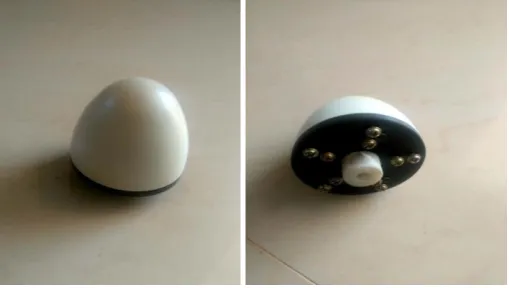
[image:2.595.179.416.344.425.2]Blades are developed by preparing the die of the blade profile and then through impression by higher impactive force. The ends of blades are drilled with two holes of 3mm diameter for fastening to the hub. The length of blade is 20 cm.
Figure 2. wind blades
B. Hub
Hub is the centre portion of wind turbine provide with internal threads for fastening the blades and center circular hole for connecting to the
shaft of PMMG motor. Once the blades are manufactured it will be fastened to hub by bolt system. Then the hub along with the blades is fixed to the rotating shaft of PMMG
Figure 3. Hub
C. Experimental Setup
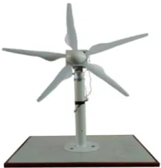
The expermintal setup of the small scale wind turbine(SSWT) is shown in the figure 4. Blades are coupled to the hub through bolts provided at hub Fig 3. The hub along with blades is
[image:2.595.171.426.517.661.2]Figure 4. Experimental Setup
4.RESULTS AND DISCUSSION A. Power Calculations
Power Pa=V*I/Motor efficiency
For the trial with velocity 6 m/s from table 1, V=2.66 volts, I=22.8 mAmps
[image:3.595.107.485.326.712.2]Assuming the motor efficiency of 60% Pa=2.66*22.8*0.001/0.60=0.101Watts
Table 1: Power Developed at 900 angle of attack for different wind velocities
sl. No.
Velocity v in m/s
Voltage V in Volts
Current I in milliamps
Actual power Pa in Watts
1 2 2.51 3.8 0.016
2 3 2.55 6.8 0.029
3 4 2.58 12.1 0.052
4 5 2.61 16.3 0.071
5 6 2.66 22.8 0.101
Figure 5. Power Developed at 900 angle of attack for different wind velocities
0.016
0.029
0.052
0.071
0.101
0.000 0.020 0.040 0.060 0.080 0.100 0.120
0 1 2 3 4 5 6 7
P
o
w
er
in w
a
tt
s
wind velocities in m/s
Power Developed at 90
0
angle of
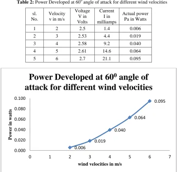
Table 2: Power Developed at 60 angle of attack for different wind velocities sl.
No.
Velocity v in m/s
Voltage V in Volts
Current I in milliamps
Actual power Pa in Watts
1 2 2.5 1.4 0.006
2 3 2.53 4.4 0.019
3 4 2.58 9.2 0.040
4 5 2.61 14.6 0.064
5 6 2.7 21.1 0.095
[image:4.595.164.430.535.651.2]Figure 6. Power Developed at 600 angle of attack for different wind velocities
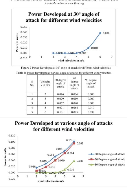
Table 3: Power Developed at 300 angle of attack for different wind velocities sl.
No.
Velocity v in m/s
Voltage V in Volts
Current I in milliamps
Actual power Pa in Watts
1 2 0.02 0 0.000
2 3 0.5 0 0.000
3 4 2.45 0.05 0.000
4 5 2.5 2.4 0.010
5 6 2.58 8.9 0.038
0.006
0.019
0.040
0.064
0.095
0.000 0.020 0.040 0.060 0.080 0.100
0 1 2 3 4 5 6 7
P
o
w
er
in w
a
tt
s
wind velocities in m/s
Power Developed at 60
0
angle of
Figure 7 Power Developed at 300 angle of attack for different wind velocities
Table 4: Power Developed at various angle of attacks for different wind velocities
sl. No.
Velocity v in m/s
30 degree angle of
attack
60 degree angle of
attack
90 degree angle of
attack
1 2 0.016 0.006 0.000
2 3 0.029 0.019 0.000
3 4 0.052 0.040 0.000
4 5 0.071 0.064 0.010
5 6 0.101 0.095 0.038
Figure 8 Power Developed at various angle of attacks for different wind velocities
0.000 0.000 0.000
0.010
0.038
-0.010 0.000 0.010 0.020 0.030 0.040 0.050
0 1 2 3 4 5 6 7
P
o
w
er
in w
a
tt
s
wind velocities in m/s
Power Developed at 30
0
angle of
attack for different wind velocities
0.016
0.029 0.052
0.071
0.101
0.006 0.019
0.040 0.064
0.095
0.000 0.000 0.000 0.010
0.038
-0.020 0.000 0.020 0.040 0.060 0.080 0.100 0.120
0 1 2 3 4 5 6 7
P
o
w
er
in w
a
tt
s
wind velocities in m/s
Power Developed at various angle of attacks
for different wind velocities
90 Degree angle of attack
60 Degree angle of attack
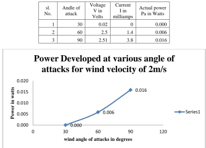
[image:5.595.114.480.111.305.2]Table 5: Power Developed at various angle of attacks for wind velocity of 2m/s
sl. No.
Andle of attack
Voltage V in Volts
Current I in milliamps
Actual power Pa in Watts
1 30 0.02 0 0.000
2 60 2.5 1.4 0.006
3 90 2.51 3.8 0.016
[image:6.595.95.503.466.745.2]Figure 9 Power Developed at various angle of attacks for wind velocity of 2m/s Table 6: Power Developed at various angle of attacks for wind velocity of 3m/s
sl. No.
Andle of attack
Voltage V in Volts
Current I in milliamps
Actual power Pa in Watts
1 30 0.5 0 0.000
2 60 2.53 4.4 0.019
3 90 2.55 6.8 0.029
Figure 10 Power Developed at various angle of attacks for wind velocity of 3m/s
0.000
0.006
0.016
0.000 0.005 0.010 0.015 0.020
0 30 60 90 120
P
o
w
er
in w
a
tt
s
wind angle of attacks in degrees
Power Developed at various angle of
attacks for wind velocity of 2m/s
Series1
0.000
0.019
0.029
0.000 0.010 0.020 0.030 0.040
0 30 60 90 120
P
o
w
er
in w
a
tt
s
wind angle of attacks in degrees
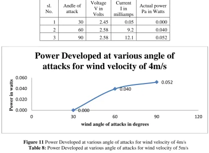
Table 7: Power Developed at various angle of attacks for wind velocity of 4m/s sl.
No.
Andle of attack
Voltage V in Volts
Current I in milliamps
Actual power Pa in Watts
1 30 2.45 0.05 0.000
2 60 2.58 9.2 0.040
3 90 2.58 12.1 0.052
Figure 11 Power Developed at various angle of attacks for wind velocity of 4m/s
Table 8: Power Developed at various angle of attacks for wind velocity of 5m/s sl.
No.
Andle of attack
Voltage V in Volts
Current I in milliamps
Actual power Pa in Watts
1 30 2.5 2.4 0.010
2 60 2.61 14.6 0.064
3 90 2.61 16.3 0.071
Figure 12 Power Developed at various angle of attacks for wind velocity of 5m/s
0.000
0.040
0.052
0.000 0.020 0.040 0.060
0 30 60 90 120
P
o
w
er
in w
a
tt
s
wind angle of attacks in degrees
Power Developed at various angle of
attacks for wind velocity of 4m/s
0.010
0.064 0.071
0.000 0.020 0.040 0.060 0.080
0 30 60 90 120
P
o
w
er
in w
a
tt
s
wind angle of attacks in degrees
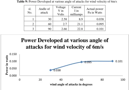
[image:7.595.88.506.132.438.2]Table 9: Power Developed at various angle of attacks for wind velocity of 6m/s sl.
No.
Andle of attack
Voltage V in Volts
Current I in milliamps
Actual power Pa in Watts
1 30 2.58 8.9 0.038
2 60 2.7 21.1 0.095
[image:8.595.102.498.471.691.2]3 90 2.66 22.8 0.101
Figure 13 Power Developed at various angle of attacks for wind velocity of 6m/s
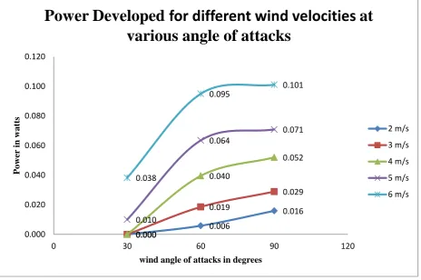
Table 10: Power Developed for different wind velocities at various angle of attacks
sl. No.
Velocity v in m/s Angle in degrees
2 3 4 5 6
1 30 0.000 0.000 0.000 0.010 0.038
2 60 0.006 0.019 0.040 0.064 0.095
3 90 0.016 0.029 0.052 0.071 0.101
0.038
0.095 0.101
0.000 0.050 0.100 0.150
0 20 40 60 80 100
P
o
w
er
in w
a
tt
s
wind angle of attacks in degrees
[image:8.595.102.493.474.689.2]Figure 14 Power Developed for different wind velocities at various angle of attacks
5. CONCLUSION
In the work an attempt is made to design and fabricate a system which can covert the wind energy into electrical energy. Further, the generated electrical energy can be used for small scale domestic applications like mobile charging, lightening of LED both in commercial and domestic spaces and CFLs and small fans.
From Figure 5 to Figure 8,
it is observed that power output of turbine increasing with respect to the velocities irrespective of angle of attack
Maximum power is developed for 900 angle of attack at maximum velocity of 6 m/s i.e., 0.101 watts
At velocities lesser than 2m/s power developed will be almost negligible (approximately equals zero)
From Figure 9 to Figure 14
it is observed that power output of turbine is more at 900 angle of attack
At 300 angle of attack, the power is developed at velocities higher than 4m/s
REFERENCES
[1] Gasch R, Twele J. Wind power plants – fundamentals, design, construction and operation: Springer, 2012.
[2] .Shailesh P. Patankar, Samir J. Deshmukh, Rucha R. Kolhekar, ― Theoretical Analysis of Horizontal Axis Wind Turbine for Low Wind Velocity‖, International Journal of Innovative and Emerging Research in Engineering Volume 2, Special Issue 1 MEPCON 2015, 93-98, p-ISSN: 2394 – 5494
0.000 0.006
0.016
0.000
0.019
0.029
0.000
0.040
0.052
0.010
0.064
0.071
0.038
0.095 0.101
0.000 0.020 0.040 0.060 0.080 0.100 0.120
0 30 60 90 120
P
o
w
er
in w
a
tt
s
wind angle of attacks in degrees
Power Developed for different wind velocities at
various angle of attacks
2 m/s
3 m/s
4 m/s
5 m/s