On-line over Current Protection System for Toroidal
Inductor using Embedded System
M.Yuvaraju1, V.Sathya2
Department of Electrical and Electronics Engineering1, 2, Anna University Regional centre: Coimbatore1, 2 [email protected] , [email protected]
Abstract- An on-line over current protection system has been designed for toroidal inductor which prevents the product failure during its manufacturing process. In toroidal inductors, the current carrying conductors are wound parallel in a form of coil. An internal short may occur due to unidentifiable black spots, scratch, thermal aging and weakness in the enamel coating in the conductors of the coil during the regular operation. The objective of this paper is to measure the current flow in the parallel wound current carrying conductors with the help of an embedded system. A sensitive miniature current transformer senses the current and the faulty differential current flow is measured between the parallel conductors and signal comparison is made using Microcontroller. Compared to the end user product cost, the cost of the designed protection system is very less and hence it is a value added feature which may save the inductor from getting burnt. This system may also be implemented for inductors which are normally used in the UPS (Un-interrupted Power Supply) systems.
Index Terms- Current transformer, Differential current flow, Peripheral Interface Controller, Product failure, Toroidal inductor, UPS (Un-interrupted Power Supply).
1. INTRODUCTION
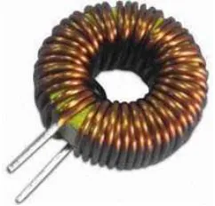
[image:1.595.326.514.405.542.2]Toroidal inductor is a passive electronic component that stores energy in its magnetic field. It consists of a circular ring shaped magnetic core of high magnetic permeability, around which a copper wire is coiled as shown in fig. 1. At present, design of the toroidal inductor is carried out with multiple parallel windings [1]. Multiple parallel winding methods provides higher voltage operation, reduced leakage flux, reduced winding resistance and reduced capacitance. The design of an inductor with toroidal core is more efficient compared to inductor with E-core resulting in reduced core loss, reduced acoustic noise and improved efficiency as shown in fig. 2.
[image:1.595.121.242.600.716.2]Fig. 1. One winding toroidal inductor
Fig. 2. Performance of Toroidal Core over E-Core
2. SYSTEM ANALYSIS
The system is analyzed by considering the problems that are faced in coiling an inductor. Thereby this paper proposes an embedded system to satisfy the manufacturers of inductors in overcoming the product failure.
2.1 Problem stated
In toroidal inductors, there occurs field failure of the product, which can be corrected in prior, during its manufacturing process. This failure is due to the internal short circuit in the coil windings because of black spots, scratches and weakness in enamel coating.
2.2 Proposed solution
[image:2.595.84.267.472.696.2]In order to overcome the above issue, this paper proposes an on-line over current protection system with the help of an embedded controller. A PIC microcontroller satisfies this need [6]. At present, this type of microcontroller is used in various electrical applications [7], [8] and consumer electronics like indoor car parking system [9]. In this paper, PIC 16F877A, an 8 bit microcontroller is used to sense and compare the differential current through the windings of an inductor with its reference current. This system may perform well at the consumer end.
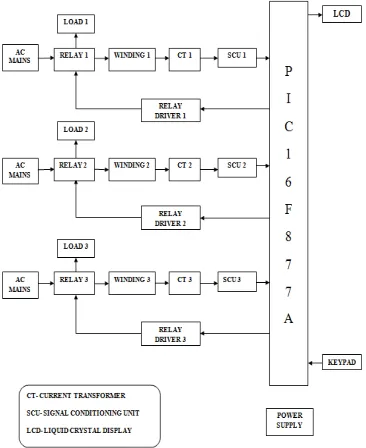
Fig. 3. Block Diagram of the prototype
As shown in fig. 3, this paper presents the over current protection for toroidal inductor consisting of three windings coiled over its core. Hence the paper explains the concept with the help of a prototype model. The prototype consists of three windings of a toroidal inductor which may be scaled up to seven windings. A current transformer (CT) is used to sense the current through each winding. Since the output current from the current transformer is an AC signal, it has to be converted into a DC analog voltage with the help of a Signal Conditioning Unit (SCU). Therefore, three SCUs are designed in the prototype. The output analog voltage of the respective SCU is fed into the PIC 16F877A microcontroller which corresponds to the current through each winding.
2.3 Control action
The microcontroller converts the analog signal into digital signal with its in-built ADC. It also compares the values of current through each winding separately with the reference current value. This reference value is dependent on the type of load used in the system. A relay is used for each winding to trip the load as shown in fig. 3. The load can be any electrical device like electric bulb, electric fan, etc. A relay driver is used to boost up the voltage required for the relay operation. When t h e r e i s h i g h c u r r e n t ( winding current > threshold current) due to the onset of defectiveness in the winding, the load can be disconnected from the system and the corresponding defective winding follows an open circuit. In the meanwhile, the defectiveness and the differential current flow in the winding are displayed on the Liquid Crystal Display (LCD). In the prototype, the defectiveness is introduced by manually incrementing the current through each winding. This is done with the help of a keypad. Therefore, the embedded system plays an important role in preventing the product failure of a toroidal inductor.
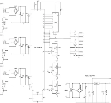
Fig. 4. Overall circuit of the protection system
regulator eliminates ripples by setting DC output to a fixed voltage.
The Signal conditioning unit conditions the input signal and forwards the output to the embedded system. A rectifier is used to convert an AC into DC. Output of the rectifier is given to the capacitor filter which removes ripples from the rectifier unit. Pure DC is given to the variable resistor through current limiting resistors. The output voltage level may be adjusted by varying the resistance value of 10 KΩ. A 5V zener voltage regulator is chosen for maintaining a constant voltage.
The relay driver circuit is enabled at certain time duration such enable pulse depends on the delayed programming of the microcontroller. The darling circuit consists of two transistor connected to form a
cascade network. If the input is set to the base of first transistor, then first transistor is turned on and its emitter current turns the other transistor. Because of this, the circuit is closed through the coil and second transistor controls the contactor that switches between normally open to closed and normally closed to open states. The inductance may affect the other components in the circuit, so a diode is connected across the coil which can prevent its chopping effect.
Parameter Value
Inductance 1.2 mH
Current rating 40 A
Density 8.9 g/cm3
No of turns ~20
the c u r r e n t transformer and toroidal inductor are given in the table 1, 2 respectively.
Table. 1. Current transformer specification
Parameter Value
Transformation ratio
63 : 0.1
Rated primary current
63 A
Precision class 3%
Operating frequency
50 HZ
Secondary turns 2 × 617 turns of 31 AWG
Secondary resistance
5.5 to 6.5 Ω
Table. 2. Toroidal inductor specification
4.
SIMULATION AND RESULT
ANALYSIS
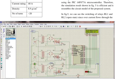
The simulation of online- over current protection system for toroidal inductor is carried out in PROTEUS simulation tool. It provides co-simulation of a complete microprocessor based design. The embedded system used in this paper is coded in embedded C using MPLAB. It is an integrated development environment for coding software program in Microchip based microcontrollers. The circuit is simulated with the transformer replacing each winding in the circuit, since they both have equal characteristics and similar method of coiling the conductors in industries. Some of the electrical components like an inductor, an electric bulb etc, are not available in this tool. Alternatively, the Light Emitting Diode (LED) is used for indication of the over current through the transformer and its defectiveness. A 5V potentiometer is used for varying the flow of current through each transformer. Thereby we set the current values that are compared using the PIC 16F877A microcontroller. Therefore, the simulation result shown in fig. 5 is efficient and it resembles the circuit model of the proposed system.
[image:4.595.64.539.391.717.2]In fig.5, we can see the switching of relays RL1 and RL2 (open state) since over current flows through the
transformer TR1 and TR2. Furthermore, the corresponding values of current are shown in the LCD display and the respective LEDs shuts off. The display shows the label of over currents (I1 and I2) to validate its defectiveness. Therefore the LED will glow only when there is normal current in the closed circuit. This simulation illustrates the overall concept of this paper. But it doesn’t reveal the exact results that are obtained in the prototype model.
The prototype of the system is shown in fig. 6. The result is accurate as it holds the electrical load (electrical bulb), whose power is 100 W. Here the reference current value is based on the below equation.
ܲ = ܸ × ܫ × cos ∅
By substituting the voltage as 220 V and the power as 100 W, the current will be obtained as 0.45 A (value of ɸ is 0.7 for electrical bulb). Keeping this current as reference, the defective winding is found with the help of an embedded system.
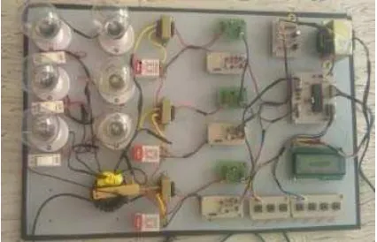
[image:5.595.71.284.517.654.2]Here, two electrical bulbs are connected serially to induce the defectiveness externally. In normal condition, single bulb per winding glows. But switching on the additional bulb externally will make both the bulbs to glow for a second after which that particular load is tripped off from the system. This in turn disconnects the respective winding of the inductor.
Fig 6. Prototype of the proposed system
5. CONCLUSION
An on-line over current protection system prevents the destruction of the component during the manufacturing process. It is very easy to design and it is implemented with less number of components. The continuous monitoring of the system is not required since an embedded system automatically disconnects the faulty winding. Hence it is concluded that this paper prevents the product failure and reduces the material loss of the manufacturer. This paper may be enhanced with wireless technology called GSM (Global System for Mobile), which may transmit the information about the defectiveness to concerned person. Hence the entire system may be operated without human intervention.
REFERENCES
[1] Jizheng Qiu, Alex J. Hanson and Charles R. Sullivan, “Design of Toroidal Inductors with Multiple Parallel Foil Windings” in Proc. IEEE COMPEL, pp. 1-6, Jun. 2013.
[2] Jizheng Qiu, Daniel V. Harburg and Charles R. Sullivan, “A Toroidal Power Inductor Using Radial-Anisotropy Thin-Film Magnetic Material Based on a Hybrid Fabrication Process” in Proc. IEEE conf. Appl (APEC), pp. 1660 – 1667, Mar. 2013.
[3] M. Araghchini, J. H. Lang, X. Yu, M. S. Kim, F. Herrault, M. G. Allen, J. Qiu, and C. R. Sullivan, “Modeling and measured verification of stored energy and loss in MEMS toroidal inductors,” in IEEE Energy Conversion Congress and Exposition (ECCE), Sep. 2012, pp. 3293 –3300. [4] Ngo, K.D.T. , Alley R.P.and Yerman, A.J.,
“Fabrication method for a winding assembly with a large number of planar layers” in Proc.IEEE. Applied Power Electronics Conference and Exposition, pp. 543 – 549, 1991.
[5] Nigam. M, Sullivan. C.R, “Multi-layer Barrel- wound foil winding design Industry Applications” in Proc. IEEE. Society Annual Meeting, pp. 1 – 7, 2008.
[6] PIC16F87XA -datasheet,Microchip-2013. [7] J. C. Lima*, A. Medeiros, V. M. Canalli*, F.
IEEE.conf. Power Electronics Congress, pp.307- 311, 2000.
[8] Dake He and R. M. Nelms, “Peak Current-Mode Control for a Boost Converter Using an 8-bit Microcontroller” in Proc. IEEE. Power Electronics Specialist Conference, pp. 938 – 943, vol.2, 2003.