14
Numerical Estimation of Thermal Analysis for an
Electronic Package
Dr. M C.Math
1Krishna Murthy N K
2Visvesvaraya Technological University PG Center1,2 Mysuru Email: [email protected]1, [email protected]2
Abstract- Numerical estimation for an electronic package has been done by the lumped modeling method and verified the results along with some commercial tools such as coolit PCB (Cooling of Printed Circuit board Software). Electronic packages which are used in electronic industries have vital role in day to day life from a small constitute such as electronic chip or components as resistor to an electronic package as combination of components on a PCB (Printed Circuit Board) situated in a box. These components dissipate heat on the layered circuit board which damages the components as well as damages the package itself so that it cannot function well. The protection of Electronic components from thermal damages requires, can be done by careful selection of layouts, dissipation levels and thermal control methods. Coolit PCB tools for thermal analysis have widely used in the PCB industries which are used to get thermal temperature for board as well as for package levels. The results obtained through these tools are compared with the results given by the ISAC (Indian Space and Aerospace center). The conduction, convection and radiation modes has been considered under typical operating conditions, to improve the temperature for the electronic packages and based on the obtained results changes are incorporated and suggested for the improvement of electronic packages thermal performance.
Index Terms- NISA- Numerically integrated element for system analysis1, ITAS (Integrated thermal analysis simulator.
1. INTRODUCTION
Electronic packages have wide application in aerospace industry within the enclosure components like printed circuit board (PCB), Diodes resisters and capacitors are incorporated, main function is to predetermine temperature inside the enclosure. Thermal analysis carried out to evaluate the heat transfer rate inside the enclosure by considering the effect of conduction and radiation on electronic components mounted inside the enclosure.
In an electronic enclosure the different task is to maintain the temperature in electronic component within the specified range. Heat energy is liberated by the individual components in an enclosure and dissipated to the surroundings. While performing Thermal analysis on PCB board and other components for cooling purpose consider the combined effect conduction and radiation by describing the mathematical model for simulation purpose.
Printed circuit board shown in the Fig.1 PCB board is supports mechanically to the electronic components mounted on it and connects them electrically by using conductive substance like solder, pads. There are two methods of components mounted on the PCB board, previously components was mounted by drilling the
PCB board. It reduces the strength of the PCB board by drilling number of small holes on it and it is difficult locate small components to the drilled hole.
The newer technic uses, solder and flux are coated over the PCB board in a specified track and components are mounted on the track.
15 Printed circuit board supports the components
mounted on it connects them electrically by using conductive substance like solder and flux.
2. NOMENCLATURE OF PCB
3. DESIGN OF PRINTED CIRCUIT BOARD
Thermal Analysis is the analysis of thermal
3.1. Simulation settings for thermal analysis
Table 1 shows Simulation settings for
thermal analysis
Table 1. Simulation settings for thermal analysis
Ambient temperature 71° Celsius (worst case)
Incoming Air pressure 0 atmospheric pressure Gravitational force 0 Default height of the
components 4mm
Number of Iterations 100
3.2. Enclosure properties
Fig.2 Enclosure properties
Fig 2 shows the enclosure properties in which size dx, dy and dz are fed into software and all values are in
mm. gravity vector in all the direction is set to zero, the working medium is specified as air. The minimum and maximum boundary conditions are entered into software with wall properties.
3.3. Board properties
Fig.3 Board properties
The printed circuit board designed will possess some properties in it, which will affect the board life. It is necessary to find out which components will produce more temperature and which components produce less temperature and then we can conclude where to give more cooling effect. The above figure indicates the board properties material, thickness percentage coverage with the components designed for this study.
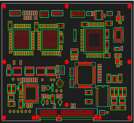
3.4. Floor Planning of SAMPLE PCB Card
16 Fig.4 Top Placement side of the SAMPLE PCB Card.
3.5. Placement of board inside the enclosure
Fig.Error! No text of specified style in document. Board Placement inside the enclosure
After placement of electronic components on the board the top view, side view, front view and a 3D view of the board are shown in Fig 5. This enclosure is used for the thermal analysis on the board. It can be seen from the figure that the heat sink is through convection mode since no additional heat absorbing components are placed on the board.
4.
THERMAL POWER ANALYSIS4.1 Thermal power distribution analysis:
a. Temperature analysis of critical components b.Temperature distribution analysis on the card
4.2 Temperature analysis
This analysis gives us graphical representation of temperature of each critical component. These are shown in the Table 2.
Table 2. The actual temperature of all the components
Name T min
74.5171 75.2668 74.8561
17
5. RESULTS AND DISCUSSION
5.1.Temperature Distribution Graphs
Fig.6 Graphical Representation of board temperature at top placement side
The maximum temperature of 91.370C is found on the board on the place where processor is placed. The temperature found is high this temperature has to be removed from the source, if this temperature is not removed it will spoil the life of the processor. The temperature generated on this part of PCB board is spread throughout the surrounding of the board which can be seen from the plots. The temperature of around 830 C is found on the other part which is near to processor, if processor is cooled chip whose temperature is 830 C will also reduce, this is because the temperature travelling from the processor will reduce. The temperature on the other two chips is found around 760C will be less damaged since least temperature on the board is 710C.
Fig.Error! No text of specified style in document. 3D Graphical Representation of board temperature
from top side
18 Fig.9 3D Graphical Representation of board
temperature from Bottom side.
5.2.Heat Flux Distribution Graphs
Fig.10 Graphical Representation of board Heat flux at top placement side
Fig.11 3D Graphical Representation of board Heat flux from top placement side
Fig.12 Graphical Representation of board Heat flux at bottom placement side
19 Fig.14 Result obtained by NISA for Verification
Problem
Fig.15 Schematic showing the temperature distribution in an Enclosure
Fig.16 Result Comparison Graph
6. CONCLUSIONS
Numerical estimation of thermal analysis for electronic components is concerned with the predicating the temperature of electronic package under specified heating environment. The electronic package existed on various electronics industries in various form for example CPU, UPS, Cellphone etc. experiences the thermal load. In this the typical package consists of a set of PCB card on which various electronics components mounted on it. The thermal analyses of these electronic packages provide the lifespan of components and packages, the design and analysis of these types of packages are a futile task. To define a good method of cooling or protecting this package, it is required to estimate the temperatures of different components used, traces of the board and the radiation energy between different boards and between boards to packages. An accurate estimation of thermal design and analysis solver development can gives an ease in thermal analysis of an electronic packages and its components with the analyst an idea to estimate the design alternatives for estimation of better thermal management process. Thermal performance levels as temperatures can be obtained under different operating conditions and safe operating levels can be defined for operation of any electronic package.
20
7. SCOPE FOR FUTURE RESEARCH
The numerical analysis provides an insight which reduces experimental costs and increases reliability for components and a better thermal design and analysis can be obtained, hence in future the demands for this analysis will be reduced for reducing laborious experimental work and to reduce cost.
REFERENCES
[1] Natural Convection Heat Transfer and Air Flow in Rectangular Enclosures With a Wavy Wall by MesutTekkalmaz,EskişehirOsmangazi University, Faculty of Engineering & Architecture, Metallurgical and Materials Engineering “Journal of Thermal Science and Technology” TIBTD Printed in Turkey ISSN 1300-3615 ©2013 [2] Numerical Investigation of Heat Transfer with
Thermal Radiation in an Enclosure in Case of Buoyancy Driven Flow by ChristophHochenauer and Johannes Wurm, Institute of Thermal Engineering, Graz University of Technology, 8010 Graz, Austria “Smart Science”Vol. 2, No. 3, pp. 116-125(2014).
[3] Numerical Investigation of Free Convection Heat Transfer in a Vertical Enclosure by Adel Alshayji, and HayaAlsaeed“International Conference on Advances in Engineering and Technology” (ICAET'2014) March 29-30, 2014 Singapore. [4] Natural Convection Heat Transfer in Rectangular
Enclosure with Sinusoidal Boundary Condition by Ayad M. Salman, Israa S. Ahmed and Sa’ib A. Hamid Assist Lectures Energy and Fuel Research Center University of Technology “Journal of Engineering and Development”, Vol. 16, No.1, March 2012 ISSN 1813- 7822.