Active Control of Irregular Buildings Considering Soil-Structure Interaction
Effects
Chang-Ching Chang1), Chi-Chang Lin2), and Jer-Fu Wang3)
1) Ph.D. Candidate, Department of Civil Engineering, National Chung-Hsing University, Taichung, Taiwan 40227, R.O.C., Email: [email protected].
2) Dean, College of Engineering, Professor, Department of Civil Engineering, and Director, Center for
Environmental Restoration and Disaster Reduction, National Chung-Hsing University, Taichung, Taiwan 40227, R.O.C., Tel: 886-4-22840438 ext 225, Fax: 886-4-22851992, Email: [email protected].
3) Postdoctoral Research Fellow, Department of Civil Engineering, National Chung-Hsing University Taichung, Taiwan 40227, R.O.C., Email: [email protected].
ABSTRACT
This paper analyzes the soil-structure interaction (SSI) effect on vibration control effectiveness of active tendon systems for an irregular building, modeled as a torsionally-coupled (TC) structure, subjected to base excitations such as those induced by earthquakes. The SSI effect is governed by the slenderness ratio of superstructure and by the stiffness ratio of soil to superstructure. An H∞ direct output feedback control algorithm that uses minimization of the entropy is implemented to reduce the seismic responses of TC structures. The control forces are calculated directly by multiplying output measurements by a pre-calculated frequency independent and time-invariant feedback gain matrix which is obtained based on a fixed-base model. Numerical simulations show that the required number of sensors and actuators and their locations highly depend on the degree of floor eccentricity. For a large two-way eccentric building, an one-way active tendon system placed at the opposite side of center of resistance (C.R.) can reduce both translational and torsional responses. If the SSI effect is significant, the proposed control system can still reduce the structural responses, but its performance is much worse than that of the corresponding fixed base model. Therefore, the TC and SSI effects should be considered in the design of active control devices, in particular, for a high-rise building founded on soft site. In this paper, an optimal, practical, and cost-effective design procedure for an active tendon system is proposed for the vibration control of irregular buildings under earthquake excitations. INTRODUCTION
Since 1970, remarkable progress has been made in the field of active control of civil engineering structures subjected to environmental loadings such as winds and earthquakes [1]. In research studies and practical applications, various control algorithms have been investigated in designing controllers, such as LQ [2-3], LQR [4-5], LQG [6,7], and H∞ control [8,9]. Among those, the H∞control theory has generated a lot of interest among researchers and, because it considers the worst external excitation case in the controller’s design, shows great potential for applications in earthquake engineering. In fact, this theory has already been applied for designing the control forces of a pair of hybrid mass damper systems to reduce the earthquake induced bending-torsion motions of an actual building in Tokyo, Japan [10].
In previous studies, most of researchers assumed that the controlled structure is a planar structure built on a fixed base. However, it is generally recognized that a real building is actually asymmetric to some degree even with a nominally symmetric plan. Because of this asymmetry, it will undergo lateral as well as torsional vibrations simultaneously, defined as torsion coupling (TC), under purely translational excitations. In addition, many buildings are constructed on soft medium where the soil-structure interaction (SSI) effect could be significant. The SSI would significantly modify the dynamic characteristics of a structure such as natural frequencies, damping ratios and mode shapes [11]. These modifications challenge the design of a structural control system since the dynamic characteristics of a structure are the required basic information that need to be provided in the control algorithm. The SSI effect on control effectiveness of multiple tuned mass dampers (MTMD) can be found in the study by Wang and Lin [12].
in an irregular building, the feedback gain matrix varies with the floor eccentricity and neglecting the TC effect could overestimate the control effectiveness. If the SSI effect is significant, the proposed control system can still reduce the structural responses, but its performance is much worse than that of corresponding fixed base model. In this paper, an optimal, practical and cost-effective design procedure for an active tendon system is proposed for the vibration control of irregular buildings subjected to earthquake excitations, including the TC and SSI effects. H∞ CONTROL FOR IRREGULAR BUILDING SYSTEMS
Without loss of generality, a single story torsionally-coupled shear building equipped with active tendon control devices at each outer frame and subjected to bi-lateral ground acceleration, x&&gand y&&g, is shown in Fig. 1. In order to introduce a certain degree of asymmetry into the model, two-way floor eccentricities between the center of mass (C.M.) and the center of resistance (C.R.) along the
x
-
and y-directions (ex and ey) are considered. The equations of motion for the controlled fixed-base system model can be expressed as) ( ) ( ) ( ) ( )
(t Cx t Kx t B1U t E1w t x
M&& + & + = + (1)
where ⎥ ⎥ ⎥ ⎦ ⎤ ⎢ ⎢ ⎢ ⎣ ⎡ = 1 0 0 0 1 0 0 0 1 M ;
⎥
⎥
⎥
⎦
⎤
⎢
⎢
⎢
⎣
⎡
=
33 32 31 23 22 21 13 12 11c
c
c
c
c
c
c
c
c
C
; ⎥ ⎥ ⎥ ⎦ ⎤ ⎢ ⎢ ⎢ ⎣ ⎡ + + − − = 2 2 2 2 2 2 2 2 2 2 2 0 0 ex y ey x ex y ey x ex y y ey x x λ ω λ ω ω λ ω λ ω λ ω ω λ ω ω θ K ; ⎥ ⎥ ⎥ ⎦ ⎤ ⎢ ⎢ ⎢ ⎣ ⎡ = θ r y x t) (x ; ⎥
⎦ ⎤ ⎢ ⎣ ⎡ = g g y x t && && ) ( w ; ⎥ ⎥ ⎥ ⎥ ⎥ ⎥ ⎦ ⎤ ⎢ ⎢ ⎢ ⎢ ⎢ ⎢ ⎣ ⎡ − − = Bx ty c Bx ty c By tx c By tx c ty c ty c tx c tx c m k m k m k m k m k m k m k m k λ θ λ θ λ θ λ θ θ θ θ θ cos 4 cos 4 cos 4 cos 4 cos 4 cos 4 0 0 0 0 cos 4 cos 4 1 B ; ⎥ ⎥ ⎥ ⎦ ⎤ ⎢ ⎢ ⎢ ⎣ ⎡ − − = 0 0 1 0 0 1 1 E
with m being the floor mass and r represents the radius of gyration of the floor. In this study, the assumption of proportional viscous damping is considered so that the superstructure possesses classical normal modes.
x y g x&& θ tx
θ θty
C.R. z g y&& x ex ey C.R.
C.M. uy,1
ux,1
uy,2
ux,2
θ
By
Bx
y
Fig. 1 TC building with active tendon control devices
The quantities λex =ex/r,
λ
ey =ey/r,λ
Bx=Bx r, λBy=By r, with Bx and By being half of floor width alongx and y directions, respectively., are dimensionless parameters that refers to the building eccentricity and to the
geometry of the structure. The vector
[
]
T2 , 1 , 2 , 1 ,() () () () )
(t =Ux t Ux t Uy t Uy t
U is the vector containing the tendon
displacements with kc, θtx, and θty being the stiffness and inclination angles of the tendon, respectively. In control theory, Eq. (1) can be conveniently rewritten in a state-space form as
) t ( ) t ( ) t ( ) t ( c
c AX BU Ew
X& = + + (2)
where
C.M.
⎥ ⎦ ⎤ ⎢ ⎣ ⎡ =
) (
) ( ) (
t t t
c x x X
& ; ⎥⎦
⎤ ⎢
⎣ ⎡
− −
= − −
C M K M
I 0
A 1 1 ; ⎥
⎦ ⎤ ⎢ ⎣ ⎡
= −
1 1
B M
0
B ; ⎥
⎦ ⎤ ⎢ ⎣ ⎡
= −
1 1
E M
0 E
are the 6×1 state vector, the 6×6 system matrix, the 6×4 controller location matrix, and the 6×2 external excitation location matrix, respectively.
Let us now define a 6×1 control output vector Z(t) and an s×1 output measurement vector Y(t) as )
( ) ( )
(t C1Xc t DU t
Z = + (3)
) ( )
(t C2Xc t
Y = (4)
where C1,D, and C2 are 6×6, 6×4 and s×6 matrices that relates the control output vector and the measurement vector to the state vector Xc and to the tendon displacement vector U. In this study, the control output vector satisfyingDTD=Iand DTC1=0 is defined as
) ( )
( )
(
4 4
4 2 4
4 2 4
4 2 2 2
t t
t c U
I 0 X 0 0
0 I
Z ⎥
⎦ ⎤ ⎢ ⎣ ⎡ + ⎥ ⎦ ⎤ ⎢
⎣ ⎡ =
× ×
× ×
× ×
α (5)
to denote the combination of floor lateral displacement responses and tendon displacements. The control weighting factor,
α
, determines the relative importance between response reduction and control force requirement. The larger value ofα
, the greater reduction of responses.α
=0 represents uncontrolled case. Moreover, C2 determines the location and number of measurements. For instance, C2=I represents full-state measurement. In the absence of control force execution time delay, the tendon displacement vector of direct output feedback control is expressed by) ( ) (t GY t
U = (6)
where G is a 4×s time-invariant feedback gain matrix. The entries of this G matrix can be obtained following the H∞ control algorithm developed by Lin et al.[13].
Once the values of the gain elements in the G matrix have been determined, the state-space formulation of the equation of motion can be expressed as:
) ( ) ( ) (
)
(t 2 c t t
c A BGC X Ew
X& = + + (7)
The controlled system poles or eigenvalues are obtained by solving the following sets of homogeneous algebraic equations
0 ) ( + 2 = −
⋅I A BGC
λ
(8)where
λ
represents complex eigenvalues of controlled system. The corresponding controlled frequency and damping ratio are given asλ
ω
c= , ξc=−Re(λ)/ωc (9)TORSION COUPLING EFFECT
A single story TC shear building, with mass equal to 2.9235×10³, uncoupled natural frequencies in the
x-,
y- and
θ
-direction equal to 3.47, 3.51 and 4.14 rad/sec and equal damping ratio for all the 3 modes (ξ
= 1.24%), is used to demonstrate the TC effect on control effectiveness of proposed control algorithm. The tendon stiffness kcis chosen to be equal to 5 10 721 .
3 × and the angle of inclination is 36o. All the different control cases are shown in Table 1, considering different conditions of the input excitation, of the eccentricity and of the control force location. The excitation is represented by the ground acceleration records obtained during the 1940 El Centro earthquake. Both transfer function and time history of floor responses of the irregular building with different number of sensors and controllers under bi-directional real earthquake excitations are compared to illustrate the optimal number and location of sensors and actuators. It is obvious that the more actuators, the better is the control performance. Based on practical and economic considerations, only one or two control forces are applied in all cases. According to previous study [13], only direct velocity feedback (DVF) is investigated in this paper since its control performance is as good as that of full state feedback.
Table 1. Excitation, measurement, and control force of different control cases
Control case Excitation Measurement Control force
λ
eyλ
exλ
By =λ
BxCase 1 [x&&g − ] [x& − r
θ
&] [ux,1 ux,2 − − ] [0.3 0.0] 3/2 Case 2 [x&&g − ] [x& − rθ
&] [ux,1 − − − ] [0.3 0.0] 3/2 Case 3 [x&&g − ] [x& − rθ
&] [ − ux,2 − − ] [0.3 0.0] 3/2 Case 4 [x&&g y&&g] [x& y& rθ
&] [ − ux,2 − uy,2] [0.3 0.0] 3/2 Case 5 [x&&g − ] [x& − rθ
&] [ux,1 ux,2 − − ] [0.3 0.3] 3/2 Case 6 [x&&g y&&g] [x& y& rθ
&] [ − ux,2 − uy,2] [0.3 0.3] 3/2 Case 7 [x&&g y&&g] [x& y& rθ
&] [ − ux,2 − − ] [0.3 0.3] 3/2For brevity of explanation, only the general cases of a two-way eccentricity will be presented, considering the one-way eccentricity cases as limit cases for one of the eccentricities going to zero.
Cases 5-7 in Table 1 represent an irregular building with two-way eccentricity under
x
&&
g and/ory
&&
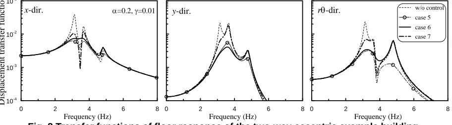
gexcitations. The controlled frequency and damping ratio with control parameters
α
=0.2 andγ
=0.01 (γ
= threshold of the H∞ norm) are listed in Table 2 while the transfer functions of the floor displacement with respect tog
x
&&
are shown in Fig 2. The comparison of Case 5 with Case 1 indicates that two-way torsional coupling increases the control damping ratios inx
,y
, andθ
directions (14.77%, 4.78% and 10.76% vs. 13.34%, 1.24%, and 3.29%). Two control forces in the same directions can adjust each other to achieve optimal control performance not only in the translation direction but also in torsion. Similar results are seen in comparing Case 4 and Case 6. As expected, it is also found that the damping associated with the torsional mode does not increase significantly because of one control force applied in each lateral direction. As obtained for Case 3 in the case of one-way eccentricity, Case 6 shows that one controller placed at each opposite side of C.R. will perform well in reducing all the structural responses. In the case of two-directional ground excitation (alongx
andy
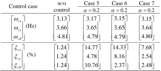
), since the first modal damping ratio increases significantly, the peak floor lateral and torsional responses are dramatically reduced, as shown in Table 3. It is also seen that one optimally placed controller (Case 7) is sufficient in reducing both lateral and torsional responses of two-way eccentric buildings under bi-directional earthquake excitations with peak control force less than 10% of the building floor weight.Table 2. Controlled frequencies and damping ratios of different control cases for the two-way eccentric example building
Case 5 Case 6 Case 7 Control case w/o
control α=0.2 α=0.2 α=0.2
⎥ ⎥ ⎥
⎦ ⎤
⎢ ⎢ ⎢
⎣ ⎡
θ
ω
ω
ω
c cy cx
(Hz)
⎥ ⎥ ⎥
⎦ ⎤
⎢ ⎢ ⎢
⎣ ⎡
4.81 3.66 3.13
⎥ ⎥ ⎥
⎦ ⎤
⎢ ⎢ ⎢
⎣ ⎡
4.79 3.65 3.17
⎥ ⎥ ⎥
⎦ ⎤
⎢ ⎢ ⎢
⎣ ⎡
4.79 3.65 3.15
⎥ ⎥ ⎥
⎦ ⎤
⎢ ⎢ ⎢
⎣ ⎡
4.80 3.64 3.15
⎥ ⎥ ⎥
⎦ ⎤
⎢ ⎢ ⎢
⎣ ⎡
θ
ξ
ξ
ξ
c cy cx
(%)
⎥ ⎥ ⎥
⎦ ⎤
⎢ ⎢ ⎢
⎣ ⎡
24 . 1
24 . 1
24 . 1
⎥ ⎥ ⎥
⎦ ⎤
⎢ ⎢ ⎢
⎣ ⎡
76 . 10
78 . 4
77 . 14
⎥ ⎥ ⎥
⎦ ⎤
⎢ ⎢ ⎢
⎣ ⎡
37 . 2
16 . 8
33 . 14
⎥ ⎥ ⎥
⎦ ⎤
⎢ ⎢ ⎢
⎣ ⎡
48 . 2
54 . 2
0 2 4 6 8 Frequency (Hz) 10-4 10-3 10-2 10-1 Displacemen t tr ansfe r f u nc
tion w/o control
case 5 case 6 case 7
0 2 4 6 8
Frequency (Hz)
0 2 4 6 8
Frequency (Hz)
rθ-dir. x-dir. α=0.2, γ=0.01 y-dir.
Fig. 2 Transfer functions of floor response of the two-way eccentric example building
Table 3. Peak displacement responses and control forces under 1940 El Centro bi-lateral Earthquake for the two-way eccentric example building
Case 5 Case 6 Case 7
Control case w/o control
2 . 0
=
α α=0.2 α=0.2
⎥ ⎥ ⎥ ⎦ ⎤ ⎢ ⎢ ⎢ ⎣ ⎡ max max max ) ( ) ( ) (
θ
r y x (cm) ⎥ ⎥ ⎥ ⎦ ⎤ ⎢ ⎢ ⎢ ⎣ ⎡ 1.58 2.06 2.75 ⎥ ⎥ ⎥ ⎦ ⎤ ⎢ ⎢ ⎢ ⎣ ⎡ 0.30 0.45 1.01 ⎥ ⎥ ⎥ ⎦ ⎤ ⎢ ⎢ ⎢ ⎣ ⎡ 0.65 0.73 1.19 ⎥ ⎥ ⎥ ⎦ ⎤ ⎢ ⎢ ⎢ ⎣ ⎡ 0.85 1.12 1.23 ⎥ ⎥ ⎥ ⎦ ⎤ ⎢ ⎢ ⎢ ⎣ ⎡ max 2 , max 2 , max 1 , ) ( ) ( ) ( y x x u u u(N) ⎥
⎦ ⎤ ⎢ ⎣ ⎡ − − ⎥ ⎥ ⎥ ⎦ ⎤ ⎢ ⎢ ⎢ ⎣ ⎡ − 2066.82 33 . 1355 ⎥ ⎥ ⎥ ⎦ ⎤ ⎢ ⎢ ⎢ ⎣ ⎡ − 1058.55 2379.10 ⎥ ⎥ ⎥ ⎦ ⎤ ⎢ ⎢ ⎢ ⎣ ⎡ − − 2743.43
SOIL-STRUCTURE INTERACTION EFFECT
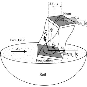
In this paper, the methodology presented in the work by Wu et al. [11] is employed to evaluate the SSI effect on the floor response of irregular buildings subjected to earthquake excitation. A two-way eccentric building supported on soil and subjected to free field ground motion along two perpendicular directions, x&&gand y&&g, is investigated. Fig.3 illustrates the responses of one-way eccentric building due to
x
&&
g. In addition to the parameters describing the TC building superstructure, a rigid foundation, of mass mb, and axially inextensible columns, ofheight h, are introduced. The soil is characterized by its mass density, ρ, shear wave velocity, vs, and Poisson’s
ratio, ν. The dynamic behavior of the entire system can be completely described by the following eight degrees of freedom:
x
, y and θ, horizontal translations and angle of twist of the floor with respect to the foundation;x
b, yband θb, horizontal translations and angle of twist of the foundation with respect to a fixed coordinate system; and x
φ
andφ
y representing the rocking about the x-axis and y-axis of the entire building. Applying the substructure method conventionally adopted in the SSI analysis, the response of the building subsystem can be solved by using the interaction forces developed at the foundation-soil interface to replace the soil subsystem. These interaction forces include the horizontal shear, Vx and Vy, the overturning moment, Mx and My , and the torque, T. Definingx
h
x
φ=
φ
,y
φ=
h
φ
y, tθ =rθ
, tbθ =rθ
b where rb is the radius of gyration of the foundation, the equations ofmotion of the superstructure can expressed as:
⎪ ⎪ ⎪ ⎭ ⎪⎪ ⎪ ⎬ ⎫ ⎪ ⎪ ⎪ ⎩ ⎪⎪ ⎪ ⎨ ⎧ = ⎪ ⎭ ⎪ ⎬ ⎫ ⎪ ⎩ ⎪ ⎨ ⎧ + ⎪ ⎭ ⎪ ⎬ ⎫ ⎪ ⎩ ⎪ ⎨ ⎧ + ⎪ ⎭ ⎪ ⎬ ⎫ ⎪ ⎩ ⎪ ⎨ ⎧ ) ( ) ( ) ( ) ( ) ( ) ( ) ( ) ( ) ( ) ( ) ( ) ( ) ( ) ( t y t x t t t y t x t t t y t x t t t y t x t t t y t x b b b φ φ θ θ θ θ && && && && && & & & && && && K C
M (10)
x
y y
y y
y y
x
y y
y y
y y
Fig. 3 Soil-building interaction system for one way eccentric building
Since the foundation impedance functions of the soil subsystem are dependent on the frequency of excitation, ω, it is most convenient to perform the dynamic analysis of the entire system in the frequency domain. This will enable us to easily combine the three subsystems: the superstructure, the foundation and surrounding soil. Following an approach developed in the work by Wu et al. [11], the response spectra of the translational and rotational motions of the structural floor can be expressed through a modification of its corresponding fixed-base structural response as:
) ( ) ( ) ( ) ( ) ( ) ( )
( ) (
) (
ω
ω
ω
ω
ω
ω
ω
ω
ω
θ
g y g
xX Y
T Y X
&&
&& ΦH S Γ
Γ
S
ΦH x + y
= ⎪ ⎭ ⎪ ⎬ ⎫
⎪ ⎩ ⎪ ⎨ ⎧
(11)
where H(ω) represents the transfer function matrix of the modal displacement of the fixed-base model while
x
Γ and Γyindicate the influence vectors of fixed-base irregular building model subjected to base excitation. The diagonal matrices Sx(
ω
), Sy(ω
) represent the modal SSI transfer matrices whose terms are functions of thefoundation’s transfer functions with respect to the free field displacements [11].
When an active control system is installed, its effects will appear as a modification of the original damping and stiffness matrices of the superstructure. Hence, the new damping matrix,Cc, and stiffness matrix, Kc, for the controlled system can be expressed as:
a
c C C
C = + , Kc=K+Ka (12)
where T
a a
a 1 BGC 1
C =− 2 ,
T b b
a 1 BGC 1
K =− 2 , are added damping and stiffness matrices provided by the control system, and 1a =
[
03×3 I3×3]
, 1b =[
I3×3 03×3]
.Since the most important parameters in the SSI analysis are the relative stiffness of the soil with respect to the superstructure, σ, and the height-to-base ratio of structure, λh, various cases have been analysed to describe the influence of these two parameters on the performance of the active control system. Small values of σ will indicate soft soil conditions while large values will indicate situations where the soil is much stiffer than the structure.
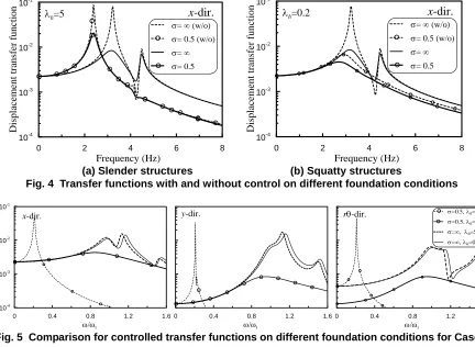
The transfer functions of floor lateral displacement to ground acceleration for the TC building of Case 3 in the previous section with two different height-to base ratios (λh = 5 (slender building) and 0.2 (squatty building)), two different soil conditions (σ=0.5 and ∞) are presented in Fig. 4 for the controlled and uncontrolled case. It is shown that, when the SSI effect is included, active control can still reduce the structural responses, although its efficiency depends on the value of
σ
andλ
h. In the case of a slender structure, the control action provides substantial reduction of the peak amplitude for the translational mode while, for a squatty structure, the control maintains its efficiency when no SSI effect is considered. In the case of a squatty structure on a soft soil (σ
=0.5), the control system still provides a reduction in the amplitude of the translational response but not as substantial as for the case of building on stiff soil.Fig. 5 shows the transfer functions of the floor lateral displacements for the case of the controlled structure supported on different soil conditions. Here it is interesting to see the SSI effect on the case of a controlled slender building on a relatively soft soil. The natural frequency of the first modes is dramatically reduced with respect to the corresponding fixed-base mode,
ω
1, and this has an effect on the control performance. These results are also confirmed in Table 4 where the peak displacement response and control performance for a structure subjected to the 1940 El Centro and 1985 Mexico City earthquake are presented. These two earthquakes are representative of rigid (El Centro) and soft (Mexico City) soil conditions.0 2 4 6 8
Frequency (Hz) 10-4 10-3 10-2 10-1 D ispla cem ent t ransfe r f unct ion
σ= ∞ (w/o)
σ= 0.5 (w/o)
σ= ∞
σ= 0.5
x
-dir.
λh=5
0 2 4 6 8
Frequency (Hz) 10-4 10-3 10-2 10-1 D isp la cemen t t ran sfe r funct ion
σ= ∞ (w/o)
σ= 0.5 (w/o)
σ= ∞
σ= 0.5
x
-dir.
λh=0.2(a) Slender structures (b) Squatty structures
Fig. 4 Transfer functions with and without control on different foundation conditions
0 0.4 0.8 1.2 1.6
ω/ω1 10-4 10-3 10-2 10-1 Di spl ace m ent t ran sf er funct ion
0 0.4 0.8 1.2 1.6
ω/ω1
σ=0.5, λh=5
σ=0.5, λh=0.2
σ=∞, λh=5 σ=∞, λh=0.2
0 0.4 0.8 1.2 1.6
ω/ω1
rθ-dir.
x-dir. y-dir.
Fig. 5 Comparison for controlled transfer functions on different foundation conditions for Case 7
Table 4. Peak displacement responses and control forces under 1940 El Centro Earthquake
(hard site,
σ
=∞) and 1985 Mexico Earthquake (soft site, σ =0.5) with SSI effect for Case 6-7∞ =
σ σ =0.5
2 . 0
= h
λ λh=5 λh=0.2 λh=5
Control case
Peak displacemen
CONCLUSIONS
This paper deals with H∞ direct output feedback control of buildings under earthquake excitations considering floor torsion coupling and soil-structure interaction effects. For a large, two-way eccentric building, one-side active tendon located far away from the center of stiffness can reduce both two-way floor translation and torsion responses. If the SSI effect is significant, the control performance based on fixed-base feedback gains can still reduce the structural responses, but is less effective than that obtained from the fixed base model. Thus, the TC and SSI effect should be considered in the design of active tendon control devices, in particular, for a high-rise building founded on soft site.
ACKNOWLEDGEMENTS
This research was supported in part by National Science Council of the Republic of China under the grant No. NSC 93-2211-E-005-025.
REFERENCES
1. Soong, T. T. and Spencer Jr., B. F., “Active, semi-active and hybrid control of structures”, Proceedings of the
12th World Conference on Earthquake Engineering, Auckland, New Zealand, 2000.
2. Kobori, T., Koshika, N., Yamada, K., and Ikeda, Y., “Seismic-response-controlled structure with active mass driver system. part 1: design”, Earthquake Engineering and Structural Dynamics, 20(2), 1991, pp. 133-149. 3. Kobori, T., Koshika, N., Yamada, K., and Ikeda, Y., “Seismic-response-controlled structure with active mass
driver system. part 2: verification”, Earthquake Engineering and Structural Dynamics, 20(2), 1991, pp. 151-166. 4. Chung, L. L., Lin, C. C., and Chu, S. Y., “Optimal direct output feedback of structural control”, Journal of
Engineering Mechanics, ASCE, 119(11), 1993, pp. 2157-2173.
5. Lin, C. C., Chung, L. L., and Lu, K. H., “Optimal discrete-time structural control using direct output feedback”,
Engineering Structures, 18(6), 1996, pp. 472-482.
6. Lu, L. T., Chiang, W. L., and Tang, J .P., “LQG/LTR Control Methodology in Active Structural Control”, Journal
of Engineering Mechanics, ASCE, 124(4), 1998, PP. 446-454.
7. Wu, J. C., Yang, J. N., “LQG Control of Lateral-Torsional Motion of Nanjing TV Transmission Tower”,
Earthquake Engineering and Structural Dynamics, 29(8), 2000, pp. 1111-1130.
8. Chang, C. C. and Lin, C. C., “On selection of control parameters for H∞ output feedback”, 2005 Proceeding of
ASME Pressure Vessels and Piping Conference, Denver, Colorado, USA, 2005.
9. Chase, G. J., Breneman, S. E., and Smith, A. H., “Robust H∞ static output feedback control with actuator saturation”, Journal of Engineering Mechanics, ASCE, 125(2), 1999, pp. 225-233.
10.Fujinami, T., Saito, Y., Morishita, M., Koike, Y., and Tanida, K., “A hybrid mass damper system controlled by H∞ theory for reducing bending-torsion vibration of an actual building”, Earthquake Engineering and
Structural Dynamics, 30(11), 2001, pp.1639-1653.
11.Wu, W. H., Wang, J. F., and Lin, C. C., “Systematic assessment of irregular building-soil interaction using efficient modal analysis”, Earthquake Engineering and Structural Dynamics, 30(4), 2001, pp. 573-594.
12.Wang, J. F., and Lin, C. C., “Seismic performance of multiple tuned mass dampers for soil-irregular building interaction systems”, International Journal of Solids and Structures, 42(20), 2005, pp. 5536-5554.
13.Lin, C. C., Chang, C. C., and Chen, H. L., “Optimal H∞ Output Feedback Control System with Time Delay”,
Journal of Engineering Mechanics, ASCE, 132(10), 2006, pp.1096-1105.