P.O. Box 140000 Huntsville, AL 35814-4000
Phone: (256) 963-8000
© 1999 ADTRAN, Inc. All rights reserved.
ADTRAN has established a Year 2000 program to ensure that our products will correctly function in the new millennium. ADTRAN warrants that all products meet Y2K specifications regardless of model or revision.
Information about ADTRAN’s Y2K compliance program is available at the following locations:
ADTRAN Web Site www.adtran.com
Product Matrix www.adtran.com/y2kfax.html Faxback Document Line (256) 963-8200
Y2K plans and product certifications are listed in the matrix.
the customer in this manual.
1. This equipment complies with Part 68 of the FCC rules. The required label is attached to the bottom of the chassis.
2. If your TSU ACE causes harm to the telephone network, the Tele-phone Company may discontinue your service temporarily. If possible, they will notify you in advance. If advance notice is not practical, you will be notified as soon as possible. You will be advised of your right to file a complaint with the FCC.
3. Your telephone company may make changes in its facilities, equipment, operations, or procedures that could affect the proper operation of your equipment. If they do, you will be given advance notice so as to give you an opportunity to maintain uninterrupted service.
4. If you experience trouble with the TSU ACE, please contact ADTRAN at (256) 963-8000 for repair/ warranty information. The telephone company may ask you to disconnect this equip-ment from the network until the problem has been corrected, or until you are sure the equipment is not malfunctioning.
5. This unit contains no user serviceable parts.
6. An FCC compliant telephone cord and modular plug is provided with this equipment. This equipment is designed to be con-nected to the telephone network or premises wiring using a com-patible modular jack which is Part 68 compliant. See installation instructions for details.
7. The following information may be required when applying to your local telephone company for leased line facilities.
Service Type SOC FIC USOC
1.544 Mbps - SF 6.0F 04DU9-BN RJ48C
1.544 Mbps - SF and B8ZS 6.0F 04DU9-DN RJ48C
1.544 Mbps - ESF 6.0F 04DU9-1KN RJ48C
RADIO FREQUENCY INTERFERENCE STATEMENT:
This equipment has been tested and found to comply with the limits for a Class A digital device, pursuant to Part 15 of the FCC Rules. These limits are designed to provide reasonable protection against harmful interference when the equipment is operated in a commer-cial environment. This equipment generates, uses, and can radiate radio frequency energy and, if not installed and used in accordance with the instruction manual, may cause harmful interference to radio frequencies. Operation of this equipment in a residential area is likely to cause harmful interference, in which case the user will be required to correct the interference at his own expense.
Shielded cables must be used with this unit to ensure compliance with Class A FCC limits.
The Industry Canada Certification label identifies cer-tified equipment. This certification means that the equipment meets certain telecommunications network protective, operational, and safety requirements. The Department does not guarantee the equipment will op-erate to the user's satisfaction.
Before installing this equipment, users should ensure that it is per-missible to be connected to the facilities of the local telecommunica-tions company. The equipment must also be installed using an acceptable method of connection. In some cases, the company's inside wiring associated with a single line individual service may be extended by means of a certified connector assembly (telephone extension cord). The customer should be aware that compliance with the above conditions may not prevent degradation of service in some situations.
Repairs to certified equipment should be made by an authorized Canadian maintenance facility designated by the supplier. Any repairs or alterations made by the user to this equipment, or equip-ment malfunctions, may give the telecommunications company cause to request the user to disconnect the equipment.
Users should ensure for their own protection that the electrical ground connections of the power utility, telephone lines and internal metallic waterpipe system, if present, are connected together. This precaution may be particularly important in rural areas.
ADTRAN will replace or repair this product within five years from the date of shipment if the product does not meet its published speci-fications or if it fails while in service. For detailed warranty, repair, and return information, see the ADTRAN Equipment Warranty and Repair and Return Policy Procedure.
Return Material Authorization (RMA) is required prior to returning equipment to ADTRAN.
Chapter 1 Introduction . . . 1-1
T1/FT1 Overview . . . 1-1 T1 Service Offerings . . . 1-1 Fractional T1 . . . 1-2 TSU ACE Overview . . . 1-2 Functional Description . . . 1-2 TSU ACE Rear Panel . . . 1-4 TSU ACE Features . . . 1-5 TSU ACE Interfaces . . . 1-5 Network Interface (NI) . . . 1-5 Nx56/64 Serial Interface . . . 1-6 Software Management . . . 1-6 Front Panel . . . 1-6 T-WATCH Pro Management Software Program . . . 1-6 TSU ACE Testing . . . 1-7 Self-Test . . . 1-7 Loopback Tests . . . 1-8 Network Loopbacks . . . 1-8 DTE Interface Loopbacks . . . 1-9 DTE Loopback . . . 1-9 Pattern Generation . . . 1-10 QRSS . . . 1-10 511 . . . 1-10 1:8 . . . 1-10 All Zeros . . . 1-10 All Ones . . . 1-10 Bridge/Router Application . . . 1-11
Chapter 2 Installation . . . 2-1
Network . . . 2-2 V.35 Nx56K/64K DTE . . . 2-3 Power Up Testing and Initialization . . . 2-4 Self-test . . . 2-4
Chapter 3 Operation . . . 3-1
Operation . . . 3-1 Front Panel . . . 3-2 General Menu Operation . . . 3-3 Data Field . . . 3-3 Display Field . . . 3-3 Arrows . . . 3-3 Example Menu Operation . . . 3-3 To select a menu item . . . 3-3 To select a submenu item . . . 3-4 To Set the Data Field . . . 3-5 To View Display-Only Data Fields . . . 3-5 To Exit Any Menu Field Operation or Display . . . 3-6 Menu Structure . . . 3-6 Four Opening Menu Functions . . . 3-8 STATUS . . . 3-8 CONFIG . . . 3-8 UTIL . . . 3-9 TEST . . . 3-10
Chapter 4 Status Menu . . . 4-1
Bipolar Violations . . . .4-4 Bit Errors . . . .4-4 PLL Alarm . . . .4-4 ERR/ALM HIST . . . .4-5
Chapter 5 Configuration Menu . . . 5-1
CONFIG. . . 5-1 Network (NI) . . . .5-2 FORMAT . . . .5-2 CODE . . . .5-2 YEL ALRM . . . .5-2 XMIT ALRM . . . .5-2 CLOCK SOURCE . . . .5-3 TSU ACE Clock Sources . . . .5-3 BIT STUFFING . . . .5-5 SET LBO . . . .5-5 RX SENSITIVITY . . . .5-5 Port . . . .5-6 RATE 56/64 . . . .5-6 CHANNELS . . . .5-6 DTE TX CLK . . . .5-6 START CHAN . . . .5-6 # OF CHAN . . . .5-7 DATA . . . .5-7 CTS . . . .5-7 DCD . . . .5-7 DSR . . . .5-7 INBAND . . . .5-8
Chapter 6 Utility Menu . . . 6-1
Chapter 7 Test Menu . . . 7-1
TEST . . . 7-1 Network Tests . . . 7-2 LOCAL LOOPBCK . . . 7-3 No Loopback . . . 7-3 Line On . . . 7-3 Payload On . . . 7-3 REMOTE LOOPBK . . . 7-3 No Loopback . . . 7-3 V.54 Inband PLB . . . 7-3 ANSI FDL LLB . . . 7-4 AT&T Inband LLB . . . 7-4 AT&T PLB . . . 7-4 TEST PATTERN . . . 7-4 No Pattern . . . 7-4 1:8 ALL DS0s . . . 7-4 511 Active DS0s . . . 7-4 QRSS Active DS0s . . . 7-4 All Zeros . . . 7-4 All Ones . . . 7-4 CLR ERRORS . . . 7-5 INSERT 511 ERRORS . . . 7-5 Run Self-test . . . 7-6 Port Tests . . . 7-7
Chapter 8 Example Operations . . . 8-1
Testing Examples . . . 8-1 Far End Looped Back Test . . . 8-1 Network Interface Test . . . 8-2
Appendix A TSU ACE Menu Tree . . . A-1
List of Figures
List of Tables
Chapter 1
Introduction
T1/FT1 OVERVIEW
T1 digital communication links have been used by the telephone com-panies (telcos) for voice transmission since the early sixties. The D4 channel bank is an example of a T1 digital carrier system that was in-troduced in the mid-seventies and is still widely used by the telcos. Communication demands of businesses continued to grow to the point that the telcos began offering T1 service directly to the public. D4 channel banks began to be used for T1 in corporate network topog-raphies for voice. The technological advances in computer develop-ment also created a demand for T1 data communication which now is a large part of the T1 traffic.
T1 Service Offerings
T1 is a digital service that is delivered to the user over two pairs of wires from the service provider. The signal operates at 1.544 mega bits per second (Mbps) and is usually extended by repeaters that are in-stalled about every mile after the first 6000 feet. The T1 signal is divid-ed into 24 time slots or digital signal level zeros (DS0s) which operate at 64 kilo bits per seconds (kbps). Each time slot is occupied by digi-tized voice or by data.
Fractional T1
Fractional T1 (FT1) lets the buyer purchase less than a full T1 circuit between two points. Most carriers offer fractional T1 in increments of 56 or 64 kbps. Connection is made to the same network elements. The network allows multiple users to share the same interoffice T1 band-width.
FT1 remains almost exclusively an inter-exchange carrier (IXC) ser-vice. Local exchange carriers (LECs) typically do not offer FT1, so the user’s proximity to the IXC’s point-of-presence (POP) is key in the sav-ings that fractional T1 offers.
FT1 local access is available in two forms, 56 kbps or a full T1 line. In 56 kbps the required number of digital data service (DDS) lines is ex-tended from the IXC POP and the bandwidth is combined at the office on an outbound T1 circuit. The user pays for the individual 56K lines and the amount of the interoffice T1 utilized. In T1 access, the user pays for a full T1 to the IXC POP and then only for the bandwidth uti-lized.
TSU ACE
OVERVIEW
This section provides a functional description of the TSU ACE, de-scribes its features, and illustrates its four interfaces Figure 1-1 on page 1-3 shows the front view of the TSU ACE, and Figure 1-2 on page 1-4 shows the rear panel.
Functional Description
The ADTRAN TSU ACE is one of several T1 multiplexers that offer complete flexibility for connection of various data sources to T1 or FT1 facilities. This family of TSU multiplexers includes the following:
rear panel to house an option module. Each module offers up to four additional data ports.
• TSU 600 - Same as the TSU with the added feature of six slots in the rear panel to house up to six option modules. Each module of-fers up to four additional data ports for a total of 24 possible data ports.
Figure 1-1. TSU ACE Unit - Front View
The TSU ACE serves as the link between user data sources such as lo-cal area network (LAN) bridges and routers, computers, CAD sys-tems, and teleconferencing equipment. The amount of bandwidth allocated to the port is custom programmable. The data terminal equipment (DTE) data can occupy contiguous or alternate channels in the T1 stream, and the channels may start at any position.
PWR ERR ALM TEST TD RD RS CS CANCEL
ENTER
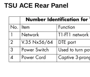
TSU ACE Rear Panel
Figure 1-2. TSU ACE Rear Panel Number Identification for TSU ACE Rear Panel
No. Item Function
1 Network T1-FT1 network interface 2 V.35 Nx56/64 DTE port
3 Power Switch Used to turn power on or off 4 Power Cord Captive 3-prong power cord
NETWORK
220VAC/60HZ .075A V.35 Nx56/64
ON OFF
TSU ACE Features
• A DS1 interface and an Nx56/64 DTE serial interface port. • Easy configuration capabilities using simplistic menus displayed
in a liquid crystal display (LCD) window operated by a front pan-el keypad.
• Timing is selectable from the network, from the Nx56/64 DTE port, or internally.
• All ones, all zeros, 511, 1:8 and QRSS test patterns.
• Extensive self-test and monitoring provides assurance of proper operation.
• Flexible channel allocation (any starting channel and alternate or contiguous).
TSU ACE Interfaces
The TSU ACE is equipped with two interfaces: Network DS1 interface per AT&T 62411 and Nx56/64 serial V.35 high speed interface. See Figure 1-3 and the following descriptions in this section.
Network Interface (NI)
The Network Interface (NI) port complies with the applicable ANSI and AT&T standards:
• Alternate mark inversion (AMI) or binary 8 zero substitution (B8ZS) coding
• Automatic or manual line build out
• Auto detect or manual settings for D4 or ESF framing • Network performance monitoring and reporting • Test loopbacks by local and remote
• Extensive self-test
Nx56/64 Serial Interface
Features of the Nx56/64 serial interface include:
• Data rates: N*56K or N*64K, where N=1 to 24 (DS0s)
• Inverted data (inverted high-level data link control (HDLC)) • A V.35 interface
• Standard V.35 connectors
• Test loopbacks with 511 pattern generation and check • Extensive self-test
Software Management
Front Panel
T-WATCH Pro Management Software Program
T-WATCH Pro is the ADTRAN management software program that allows the user to control the TSU ACE from a PC. It provides com-plete control over the configuration of the TSU ACE using a graphic interface.
The T-WATCH Pro program displays the same status and perfor-mance data as the front panel LCD. This data is displayed in the form of tables and graphs.
The TSU ACE can be remotely configured using T-WATCH Pro. The ESF FDL or the 8K inband channel is used to connect to the TSU ACE. The PC with T-WATCH Pro installed on it must be connected to an ADTRAN T1 CSU/DSU with a control/chain in port. Such products include: TSU, TSU LT, TSU ESP and the TSU XX0 family of T1 multi-plexers. See Figure 5-6 on page 5-9.
TSU ACE Testing
The TSU ACE offers three forms of testing:
• Self-test • Loopback tests
• Pattern generation and detection
Self-Test
The self-test checks the integrity of the internal operation of the elec-tronic components by performing memory tests and by sending and verifying data test patterns through all internal interfaces. Although actual user data cannot be passed during these tests, the self-test can run with the network and DTE interfaces in place and without dis-turbing any external interface.
In addition to the specified self-tests, background tests are run on var-ious parts of the internal electronics. These run during normal opera-tion to confirm continued correct funcopera-tioning. The background tests include:
• Monitoring the phase locked loop for lock
• Standard background network performance monitoring, as re-quired by ANSI T1.403 and AT&T 54016 for which the results are stored
Loopback Tests
A number of different loopbacks can be invoked locally from the front panel or remotely by using special inband codes (AT&T D4 network loop up/loop down codes and V.54 loop up/loop down codes for the Nx56K/64K serial interface). Additionally the loopbacks can be re-motely controlled by out-of-band commands via the T1 ESF facility data link (FDL), or from T-Watch via a modem connection. Network and DTE interface loopbacks are discussed in this section.
Network Loopbacks
There are three types of network loopbacks; see Figure 1-4 on page 1-9.
Line Loopback
Loops all of the received data back toward the network. The transmitted data is the identical line code that was received, including any bipolar violations or framing errors.
Payload Loopback
Data Loopback
Loops back all active DS0s and inserts idle code into unoccu-pied DS0s.
Figure 1-4. Network Loopback Tests
DTE Interface Loopbacks
The Nx56K/64K serial interface offers a DTE loopback. See Figure 1-5.
DTE Loopback
Loops all data from the DTE back towards the DTE. This loopback may be initiated by using front panel or T-Watch commands. The DTE (or the external test equipment) must provide a test pattern in or-der to check the DTE interface.
Pattern Generation
The TSU ACE offers five available test patterns: QRSS, 511, 1:8, All Ones, and All Zeros.
QRSS
The TSU ACE has an internal QRSS pattern generator and detector. The pattern only appears in the DS0s assigned to the Nx56K/64K port. The QRSS test pattern can be used in conjunction with network loop-backs to perform end-to-end tests.
511
The TSU ACE has an internal 511 pattern generator and detector. The pattern only appears in the DS0s assigned to the Nx56K/64K port. The 511 test pattern can be used in conjunction with network loop-backs to perform end-to-end tests.
1:8
The 1:8 is a stress pattern which places the maximum number of 0s in the transmitted data. This is always done over all DS0s. This pattern is used in conjunction with external test equipment to determine if the T1 line is performing acceptably under a stress condition. Each chan-nel of the T1 has only one bit set.
All Zeros
Generates an all zeros pattern in every channel.
All Ones
Bridge/Router Application
Utilizing the V.35 DTE interface, a bridge or router can be interfaced to the network. The bandwidth used is programmable at Nx56 or Nx64 data rates for T1 or FT1 service. The bandwidth can be config-ured to use contiguous or alternate channels. Figure 1-6 shows a sim-ple bridge application.
Chapter 2
Installation
INSPECTING FOR DAMAGES
Carefully inspect the TSU ACE for any shipping damage. If damage is suspected, file a claim immediately with the carrier and then contact ADTRAN Customer Product Service. If possible, keep the original shipping container for use in shipping the TSU ACE back for repair or for verification of damage during shipment.
ITEMS SHIPPED BY ADTRAN
The following items are included in the ADTRAN shipment:
• TSU ACE unit
• Line interface cable: an 8-position modular to 8-position modular • TSU ACE User Manual
• Loopback plug
ITEMS PROVIDED BY CUSTOMER
POWER CONNECTION
Each TSU ACE unit is provided with a captive eight-foot power cord, terminated by a three-prong plug which connects to a grounded pow-er receptacle.
WIRING
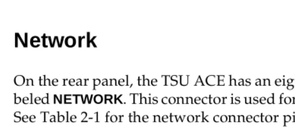
Network
On the rear panel, the TSU ACE has an eight-position modular jack la-beled NETWORK. This connector is used for connecting to the network. See Table 2-1 for the network connector pin assignments.
Table 2-1. Network Pin Assignments Power to the TSU ACE must be from a grounded 115 VAC, 60 Hz power source.
Connector Type Product Number
(USOC) RJ-48C AMP# 555164-2
PIN NAME DESCRIPTION
1 R1 RXDATA-RING Receive data from the network
2 T1 RXDATA-TIP —
3 UNUSED —
4 R TXDATA-RING Send data towards the network
5 T TDXDATA-TIP —
V.35 Nx56K/64K DTE
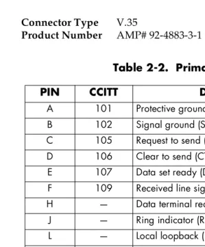
The pinout for this connector is shown in Table 2-2.
Table 2-2. Primary V.35 Pin Assignment
Connector Type Product Number
V.35
AMP# 92-4883-3-1
PIN CCITT DESCRIPTION
A 101 Protective ground (PG)
B 102 Signal ground (SG)
C 105 Request to send (RTS) from DTE
D 106 Clear to send (CTS) to DTE
E 107 Data set ready (DSR) to DTE
F 109 Received line signal detector (DCD) to DTE
H — Data terminal ready (DTR) from DTE
J — Ring indicator (RI)
L — Local loopback (LL)
N — Remote loopback (RL)
R 104 Received data (RD-A) to DTE
T 104 Received data (RD-B) to DTE
V 115 RX clock (RC-A) to DTE
X 115 RX clock (RC-B) to DTE
P 103 Transmitted data (TD-A) from DTE
S 103 Transmitted data (TD-B) from DTE
Y 114 TX clock (TC-A)
AA 114 TX clock (TC-B)
U 113 External TX clock (ETC-A) from DTE
W 113 External TX clock (ETC-B) from DTE
POWER UP TESTING AND INITIALIZATION
When shipped from the factory, the TSU ACE is set to factory default conditions. At the first application of power, the unit automatically ex-ecutes self-tests followed by an initialization sequence which sets up the unit.
Self-test
Upon a power-up or commanded self-tests, the LCD displays
ADTRAN TSU ACE INITIALIZING and the LEDs illuminate sequentially.
When the self-test is completed with no failures detected, the LCD mo-mentarily displays ALL TESTS PASSED. If a failure is detected, it is dis-played in the LCD window. The automatic self-test procedure consists of the following steps:
Board level tests
• Random access memory (RAM) tests; erasable programmable read only memory (EPROM) checksum.
• On-board data path. Sending a known test pattern through an on-board loop.
Unit level tests
Chapter 3
Operation
OPERATION
Front Panel
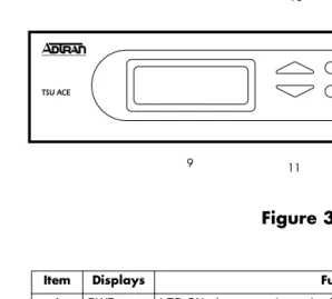
The TSU ACE front panel is shown in Figure 3-1. Unit features are identified by call-outs.
Figure 3-1. Front Panel Layout
Item Displays Function 1 PWR LED ON when power is received by TSU ACE.
2 ERR LED ON when errored events have happened in the last second. 3 ALM LED ON when an alarm condition exists.
4 TEST LED ON when unit is in test mode. 5 TD LED ON when DTE data is being received. 6 RD LED ON when DTE data is being received.
7 RS LED ON when request to send (RTS) active from DTE.
8 CS LED ON when TSU ACE has clear to send (CTS) active toward DTE. 9 LCD A 2X16 LCD window that displays menu items used in configuration and
displays information useful in monitoring the unit.
Operation Keys:
10&11 Up/Down Keyboard arrows used to travel up/down menu trees.
Arrows increase/decrease numeric values and scroll through selec-tions.
GENERAL MENU OPERATION
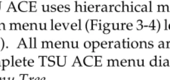
The TSU ACE uses a multilevel menu structure containing both menu items and data fields. All menu operations and data are displayed in the LCD window. The menu items are numbered and can be viewed by using the Up and Down arrows.
Data Field
A menu item followed by a colon (:)identifies an editable data field.
Display Field
A menu field followed by alarm or error information.
Arrows
Menus that display small Up or Down arrows in the lower right corner indicate there are more menu items than are viewable on a two-line LCD. The additional menu items are accessed with the
Up or Down arrows.
Example Menu Operation
To select a menu item
Step Action
1 Use the Up and Down arrows to place the cursor on the desired menu item (in this example CONFIG).
See Figure 3-2 on page 3-4.
2 Place the cursor on the number 2 and press
The unit responds by displaying the first two available submenu fields. The cursor is on the first field. If there are more than two menu fields, a Down arrow will be visible in the lower right corner.
Figure 3-2. Cursor on Menu Item
To select a submenu item
The unit responds by displaying the first two available data field items. The cursor is on the number of the first item. When there are more than two data field items for the selected submenu, a Down arrow
will be visible in the lower right corner.
Figure 3-3. Sub-Menu Fields
Step Action
1 Use the same operation used to select an opening menu item.
To Set the Data Field
Data fields that are available for editing are preceded by a colon (:).
The unit is set for the value shown in the data field and the cursor moves back to the submenu item position indicating the operation is complete. You may select another submenu field or press Cancel to re-turn to the submenu.
To View Display-Only Data Fields
An example of a display only data field can be found by selecting the following menu choices:
Step Action
1 Press Enter while the cursor is located on the submenu item number. The cursor moves to the data field (to the right of the submenu item name).
2 Use the Up and Down arrows to scan the available value settings, which display in the data field position one at a time.
3 When the desired value is in the data field position, press
Enter to set the value.
Cancel is available any time during the operation. If used
prior to pressing Enterafter making a data change, the original data value is restored and the cursor returns to the submenu field.
Step Action
1 Select STATUS from the main menu.
2 Select submenu CURR ERR/ALM.
LOSS OF SIGNAL INACTIVE/ACTIVE is displayed, giving
To Exit Any Menu Field Operation or Display
Press Cancelas many times as required to return to the desired menu level.
Menu Structure
The TSU ACE uses hierarchical menus to access its many features. The main menu level (Figure 3-4) leads to submenus (see Figure 3-5 on page 3-7). All menu operations are displayed in the LCD window. The complete TSU ACE menu diagram is shown in Appendix A, TSU ACE Menu Tree.
Figure 3-4. TSU ACE Main Menu Screen
Figure 3-5. TSU ACE Main Menu
Menu flow is normally depicted from left to right. Arrows on the low-er right of the screen indicate the direction of additional menu items. At every level of the menu, pressing Cancel returns the system to the previous menu level. Repeatedly pressing Cancel returns the system to the main menu.
The opening menu is the access point to all other operations. There are four main menu items, STATUS, CONFIG, UTIL, and TEST. Each main menu item has several functions and submenus to identify and access specific parameters. Each main item menu contains a complete menu diagram to identify the location of each operation.
NI PERF REPORTS
STATUS CURR ERR/ALM
ERR/ALM HIST NETWORK (NI)
MAIN MENU CONFIG PORT
TIME/DAY
UTIL SOFTWARE REV
REINIT UNIT NETWORK TESTS ADDRESS TEST RUN SELFTEST SET PASSCODE
Four Opening Menu Functions
STATUS
The Status menu provides the ability to view the status of the TSU ACE operation. This menu includes the following items:
NI PERF REPORTS
Used to view the user set of data on the Network Interface Performance Reports in compliance with ANSI T1.403 and AT&T document TR54016.
CURR ERR/ALM
Used to view current errors/alarms which are being reported by the TSU ACE.
ERR/ALM HIST
Used to view and clear history errors and alarms.
CONFIG
The Configuration menu is used to set the TSU ACE operational con-figuration. This menu includes the following sub-items.
NETWORK (NI)
Used to set all of the parameters associated with the network interface.
PORT
UTIL
The Utility menu is used to view and to set system parameters. This menu includes the following sub-items:
TIME/DATE
Accesses the display and allows the setting of the current time and date.
SOFTWARE REV
Displays the version number of the current software revision level. This information is required when requesting assis-tance from ADTRAN Customer and Product Service or when updates are needed.
REINIT UNIT
Used to initialize the unit. This menu item is not used to re-store the factory default settings for all parameters.
ADDRESS
Used to view and change the current Unit Address used for control port access.
SET PASSCODE
Allows a passcode to be set.
KEYPAD
Used to lock the front panel keypad. With the keypad locked, the unit configuration can be viewed but not changed.
FACT RESTORE
TEST
The Test menu is used to initiate different types of tests of the unit and to view test results. Test results are displayed in the LCD window. The menu contains three sub-items.
NETWORK TESTS
Used to control the activation of loopbacks and the initiation of data test patterns.
RUN SELF TEST
Used to execute an internal self test.
PORT TESTS
Used for the testing of the DTE port.
Each of these menu items is discussed in detail in the following chap-ters.
Chapter 4
Status Menu
STATUS
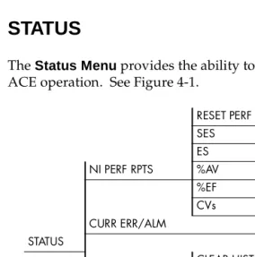
The Status Menu provides the ability to view the status of the TSU
ACE operation. See Figure 4-1.
Figure 4-1. Status Menu RESET PERF CNTRS
SES ES NI PERF RPTS %AV
%EF LOSS OF SIGNAL
CVs AIS ALARM
CURR ERR/ALM OUT OF FRAME
STATUS YELLOW ALARM
CLEAR HISTORY RED ALARM LOSS OF SIGNAL CODE VIOLATIONS AIS ALARM BIPLOAR VIOL OUT OF FRAME FRAME BIT ERRORS YELLOW ALARM PLL ALARM ERR/ALM HIST RED ALARM
NI PERF RPTS
The Network Interface Performance Reports displays the user copy of the performance data. The TSU ACE maintains this performance data on the network in compliance with ANSI T1.403 and AT&T document TR54016. The data displayed is data accumulated over the last 15 min-utes and over the last 24 hours.
These fields cannot be edited, only cleared as previously discussed. Only the user copy of performance data is cleared. See Figure 4-2. Continue with standard operating procedures to exit the display.
Figure 4-2. Severely Errored Seconds Screen
SES
Number of severely errored seconds.
ES
Number of errored seconds.
%AV
Percentage of available seconds.
%EF
Percentage of error free seconds.
CVs
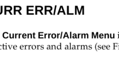
CURR ERR/ALM
The Current Error/Alarm Menu is used for viewing currently Active/
Inactive errors and alarms (see Figure 4-3).
Figure 4-3. Loss of Signal (Current Errors/Alarms) Screens
The Up and Down arrows are used to access the complete display of the
errors/alarms that are currently active. The following are alarms and errors which can be seen.
Loss of Signal
No pulses received at NI.
AIS Alarm
Unframed All-Ones received at NI.
Out of Frame
No framing pattern sync at NI.
Yellow Alarm
Receiving yellow alarm pattern from NI.
Red Alarm
Loss of signal/out of frame (LOS/OOF) causing red alarm at NI.
Code Violations
Cyclic redundancy check (CRC) errors in ESF, or bipolar violations (BPVs) in Superframe Format (SF) were received at NI.
Bipolar Violations BPVs in SF or ESF.
Bit Errors
Frame Bits received incorrectly at NI.
PLL Alarm
ERR/ALM HIST
The ERROR/ALARM HISTORYmenu is used for viewing history of
errors and alarms. If an alarm has occurred since the last CLEAR HIS-TORYselection, the menu is active. If the condition has not occurred then the menu is inactive (see Figure 4-4).
Figure 4-4. Clear History Screen
These conditions are the same as for the CURR ERR/ALM submenu except that these are history Alarm/Errors instead of current
Chapter 5
Configuration Menu
CONFIG
The Configuration Menu is used to set the TSU ACE operational
con-figuration, including all of the network interface parameters, and the allocation of the DS0s and the port parameters. See Figure 5-1.
Figure 5-1. Configuration Menu
FORMAT CODE YEL ALRM XMIT PRM CLOCK SOURCE NETWORK (NI) BIT STUFFING
SET LBO RX SENSITIVITY
CONFIG
RATE 56/64 CHANNELS DTE TX CLK START CHAN PORT # OF CHAN
Network (NI)
The NETWORK (NI) menu is used to access the configuration of
pa-rameters associated with the network interface in the TSU ACE. There are eight submenu items that include setting the format, the line build out (LBO), and the clock source (see Figure 5-2).
Figure 5-2. Network Submenu
The fields and parameters available are:
FORMAT
Sets the frame format for the NI. Choices: D4, ESF, AUTO
CODE
Sets the line code for the NI. Choices: AMI, B8ZS
YEL ALRM
Enables and disables the transmitting of yellow alarms. Choices: ENA (enable), DISA (disable)
XMIT ALRM
Enables and disables the transmitting of performance report messag-es (PRM) data on the facility data link (FDL). The PRM data continumessag-es to be collected even if XMIT PRM is disabled (possible only with ESF Format).
Choices: ENA, DISA
CLOCK SOURCE
Selects the clock source for transmission toward the network from the NI.
Choices: NETWORK, DTE, INTERNAL
TSU ACE Clock Sources
The TSU ACE is operable from various clock sources which permits it to perform properly in many different applications. The network in-terface clocking options are set by using the Network Configuration menu options. Three clock source options are available:
• Network timed • DTE timed • Internal timing
Network Timing
The network is the source of timing. The received data clock-ing is looped back to the network, where it is used to deter-mine the transmission timing. This option is also referred to as looped timed as the transmission clock is derived from the received clock. See Figure 5-3.
Figure 5-3. Network Timed Clock Source
DTE Timing
The DTE is the source of timing. The TSU ACE uses the in-coming DTE clock to determine the transmission timing. This is typically used in applications such as limited distance line drivers, where it is necessary to have the DTE as the primary clock source. See Figure 5-4.
Internal Timing
The TSU ACE is the source of timing. The TSU ACE is config-ured to use its own internal oscillator as the source of timing. Applications include private line driver circuits where one end is set to network and the other to internal. See Figure 5-5.
Figure 5-5. Internal Clock Source
BIT STUFFING
When enabled, BIT STUFFING causes the TSU ACE to monitor for ones (1s) density violations and insert a one (1) when needed to main-tain ones at 12.5 percent. This option should be disabled if B8ZS is en-abled, if Nx56 is selected, or if alternate channels are being used. All of these other options already ensure pulse density requirements. Choices: ENA, DISA
SET LBO
SET LBO selects the line build-out for the network interface. In AUTO
mode, the TSU ACE sets the LBO based on the strength of the receive signal.
Choices: 0dB, AUTO, -22.5dB, -7.5dB, -15dB
RX SENSITIVITY
RX SENSITIVITY selects the desired receiver sensitivity setting. The
factory default is NORMAL which is adequate for most applications. The extended setting should be used only in applications where the
Port
The menu item PORT is used to select and configure the parameters associated with the V.35.
RATE 56/64
This sets the base rate of the interface. The actual data rate depends on the number of DS0s assigned to the Nx port. The DTE data rate vs. the number of DS0s appears in the appendix DTE Data Rate Chart. Choices: 56K, 64K
CHANNELS
This sets the unit to use alternate or contiguous channels in the T1 data stream. If more than 12 channels are used, then contiguous must be used. If not, then alternate channels may be used to meet pulse den-sity requirements (only necessary for Nx 64 without B8ZS). If other than a private network, the carrier must be notified of this choice. Choices: ALT (alternate), CONT (contiguous)
DTE TX CLK
Controls the clock used by the TSU ACE to accept the transmit (TX) data from the DTE. Most applications will allow for this to be set to
INTERNAL. If the interface cable is long (causing a phase shift in the
data) the clock can be selected as INT/INV (Internal/Inverted). This switches the phase of the clock which should compensate for a long ca-ble.
The factory default setting for the DTE TX CLK option is AUTO. The
AUTODTE TX CLKsetting will allow the TSU ACE to automatically
de-tect the delay from the DTE device to the TSU ACE and set the proper phase of the clock. This feature will automatically select between the
INTERNAL and INT-INV settings.
If the DTE provides a clock with TX data, the clock selection is set to
EXTERNAL. The TSU ACE will depend on an externally supplied
clock to accept the TX data.
START CHAN
Used to select the channel in which the T1 stream will start. The set-ting must be consistent with carrier if using a public network. Choices: 01 through 24
# OF CHAN
Used to select the number of DS0s (channels) that are to be used. The corresponding DTE rate will be this number times 56K or 64K. Choices: 01 through 24
DATA
Used to control the inverting of the DTE data. This inversion can be useful when operating with an HDLC protocol. Often used as a means to ensure ones (1s) density. TSU ACEs on both ends must have identical option settings.
Choices: NORMAL, INVERT
CTS
Used to control characteristics of CTS.
Choices: NORMAL (see Table 5-1), FORCE ON
DCD
Data Carrier Detect - Indicates to the DTE when a valid signal is being received at the Network Interface.
Choices: NORMAL (see Table 5-1), FORCE ON
DSR
Data Set Ready - This signal indicates to the DTE when the DCE is turned ON and ready for operations.
Table 5-1. Normal Mode Operation
INBAND
The Inband Configuration Channel is used to enable/disable an 8 kbps remote configuration channel (see Figure 5-6). When this option is set to ON, the first DS0 occupied operates in 56K mode and the DTE clock rate is reduced by 8 kbps. The TSU ACE uses this 8 kbps channel to send and receive configuration data across a T1 span. The in-band channel allows the PC connected to the chain-in port on TSU A to monitor/configure both TSU A and B. This feature is useful when FDL connectivity is not available across the T1 span.
The 8 kbps channel is only taken out of the first DS0. If two 64K DS0s are mapped, the DTE rate would be 120 kbps instead of 128 kbps. This menu option can also be set to AUTO, which activates the Inband Channel only when commands are sent from T-Watch to the remote unit (TSU B in Figure 5-6 on page 5-9). If no T-Watch activity is detect-ed for 10 minutes, the Inband Channel is deactivatdetect-ed.
Conditions which cause the Port Control Signals to be deactivated SIGNAL RTS V.54
LOOP BK 511 TST ON SELF-TEST ACTIVE NETWK TEST ACTIVE NO DS0 MAPPED NETWORK ALARM CTS Follows OFF OFF OFF OFF OFF OFF
DCD — — — OFF — OFF OFF
DSR — OFF OFF OFF OFF OFF —
Figure 5-6. Inband Remote Configuration
TSU A must have a control/chain-in port for this
Chapter 6
Utility Menu
UTIL
The Utility Menu is used to view and to set system parameters. See
Figure 6-1. This includes setting the time and date and resetting all pa-rameters to factory values or to re-initialize the unit. This menu is also used to view the unit’s software revision and the unit ID setting.
Figure 6-1. Utility Menu TIME: HH:MM:SS
TIME/DATE DATE: MM/DD/YY
SOFTWARE REV Displays current software revision
UTIL REINIT UNIT
ADDRESS
SET PASSCODE
KEYPAD
FACT RESTORE
Time/Date
TIME/DATE is used to view or to edit the current time and date. The
time and date are maintained during power off conditions (see Figure 6-2).
Figure 6-2. Time/Date Screen
Table 6-1. Editing the Time/Date
If you want to .... Press this key
Record the entry and move to the next editing position.
Enter (after any numeric change)
Move to the next editing position or field
Enter without making any
changes at the cursor.
The up and down arrow keys
Software Rev
Use the SOFTWARE REVISION submenu to access the display of the current software revision level. This information is required when re-questing assistance from ADTRAN Customer Service or when up-dates are needed.
Reinit Unit
REINIT UNIT submenu is used to re-initialize the unit. This menu
item is not used to restore the factory default settings for all parame-ters.
Address
ADDRESS is used to access the current UNIT ADDRESS setting. Unit
identification numbers must be between 000 and 256. See Figure 6-3.
Figure 6-3. Address Screen
Set Passcode
Set Passcode allows a passcode to be set for T-Watch and keypad
Keypad
Allows the user to lock or unlock the front panel keypad. This feature keeps the unit configuration from being changed by unauthorized personel.
When the keypad is Locked, option settings can be viewed but not changed. The user-selected passcode is set on the Set Passcode screen and is not required to lock the unit.
When Unlocked is selected, the user is required to enter the four-digit passcode. If an incorrect passcode is entered, the unit will remain locked.
Fact Restore
The Factory Restore submenu is used to restore the factory default
Chapter 7
Test Menu
TEST
The TEST MENU is used to initiate different types of tests of the unit
and to view test results (see Figure 7-1 on page 7-2). Test results are displayed in the LCD window. The menu contains three sub-items.
Figure 7-1. Test Menu Tree
Network Tests
Network tests are used to control the activation of loopbacks and the initiation of data test patterns.
The network tests are run on the network interface (NI). Three differ-ent test configurations can be selected to determine the type of loop-back and the pattern to run. Test results are displayed in the LCD window. See Figure 7-2 on page 7-3.
NO LOOPBACK
LOCAL LOOPBK LINE ON NO LOOPBACK PAYLOAD ON V.54 INBAND PLB REMOTE LOOPBK ANSI FDL LLB NETWORK TESTS AT&T INBAND LLB
TEST PATTERN NO PATTERN ANSI FDL PLB 1:8 ALL DS0s AT&T PLB TEST 511 ACT. DS0s
QRSS ACT. DS0s ALL ZEROS ALL ONES CLR ERRS (and error display) INSERT 511 ERRRORS
RUN SELFTEST (Displays results) PORT TESTS DTE LOOPBK: OFF
Figure 7-2. Local Loopback Screen
LOCAL LOOPBCK
There are three available choices for setting the local loopback:
No Loopback
Deactivates the loopback.
Line On
Activates the line loopback.
Payload On
Activates the payload loopback.
REMOTE LOOPBK
Activates the same loopbacks as the LOCAL but at the far end. This uses either the inband loopup code as specified by AT&T 62411 for line loopback (ATT In-Band LLB), or the FDL as specified in ANSI T1.403 for payload and line loopback codes. An FDL (formerly TABS) maintenance message corresponding to AT&T TR54016 can be used for payload loopback as well.
No Loopback
Deactivates the loopback.
V.54 Inband PLB
ANSI FDL LLB
Initiates the transmission of an FDL line loop-up code toward the far end.
AT&T Inband LLB
Activates the line loopback using inband code.
AT&T PLB
Initiates the transmission of the PLB maintenance on the FDL.
TEST PATTERN
Sets the pattern for the test and initiates the transmission of the pat-tern. There are four patterns available.
No Pattern
The test is terminated by selecting NO PATTERN.
1:8 ALL DS0s
Generates a 1 in 8 pattern in all DS0s.
511 Active DS0s
Generates a 511 test pattern and inserts it into active DS0s.
QRSS Active DS0s
Generates a QRSS test pattern and inserts it into active DS0s.
All Zeros
Generates an all zero's pattern in every channel.
All Ones
Generates an all one’s pattern in every channel.
CLR ERRORS
CLR ERRORS has two functions. First, it clears out the QRSS and 511
pattern error total when you press Enter. Second, it displays a total of the QRSS or 511 pattern errors. If pattern errors are being received, the display is updated accordingly. See Figure 7-3.
Figure 7-3. Clear Errors Screen
This menu function is very useful for testing end-to-end integrity of the network. First loop up the far end TSU ACE. Then send a 511 or QRSS pattern from the local TSU ACE. The CLR ERRORS screen can then be used to determine if the link is functioning properly by verify-ing that no errors are beverify-ing counted.
INSERT 511 ERRORS
Run Self-test
This menu selection is used to execute an internal self test. This is the same self test that is performed automatically at power up. The results of the self tests are displayed in the LCD. Upon invoking the com-mand, the LCD displays INITIALIZING and test failures are displayed in the LCD window. See Figure 7-4. The following tests are performed during self-test:
1. RAM tests; EPROM checksum
2. On board data path; sending a known test pattern through an on-board loop
3. Front panel LED verification 4. Phase locked loop verify
If a failure is detected, note the failure number prior to contacting ADTRAN Technical Support.
Port Tests
Port Tests are used to control the activation of a DTE loopback. This test loops data received at the V.35 interface back towards the DTE. See Figure 7-5.
Chapter 8
Example Operations
TESTING EXAMPLES
Prior to actually using the TSU ACE to pass data, it is recommended to run tests on the circuit. Testing consists of sending a test pattern from end-to-end and checking for errors in the pattern. There are two types of tests used to accomplish this:
• Send the pattern from one end and loop back the far end. • Send the pattern from both ends and check at both ends.
Far End Looped Back Test
Network Interface Test
The Network Interface Test can be run with any channel setup because the 511 and QRSS patterns are always sent in the occupied channels.
1. Select TEST from the Main Menu (see Figure 8-1).
Figure 8-1. Main Menu TEST Selected
2. Use the arrows to place the cursor on TEST. 3. Press Enterto select.
Result: The first two TEST submenu items display. See Figure 8-2.
Figure 8-2. Test Menu with NETWORK TESTS Selected
Result: Beginning display of the submenu items.; each menu item can be selected with the Up and Down arrows
The Local Loopback test menu is shown in Figure 8-3.
Figure 8-3. Local Loopback Test Menu
The menu offers the following options:
• Line On • Payload On • No Loopback
The menu options for the Remote Loopback test menu are shown in Figure 8-4.
The menu options for the Remote Loopback are:
• No Loopback • V.54 Inband PLB • ANSI FDL LLB • AT&T Inband LLB • ANSI FDL PLB • AT&T FDL PLB
The Test Pattern screen is shown in Figure 8-5.
Figure 8-5. Test Pattern Screen
The menu options available for the Test Pattern screen are:
• No Pattern • 1:8 all DS0s • QRSS Active DS0s • 511 Active DS0s • All Zeros • All Ones
1. Use the arrows to place the cursor on REMOTE LOOPBK. 2. Press Enterto select.
When completed, do the following:
1. Use the arrows or the number 3to select Test Pattern. 2. Press Enter to activate the Test Pattern submenu.
3. Use the arrows to select 511 ACT. DS0s or QRSS ACT. DS0s. 4. Press Enter to activate the selection.
Results: The TSU ACE always checks for 511 and QRSS errors. The results of this check are shown under submenu item 4 (see Figure 8-6).
Figure 8-6. Clear Errors Screen
When through viewing the results, do the following:
1. Press Cancelto return to submenu item Test Pattern. 2. Select No Pattern to turn off the test pattern.
Result: The far end remains in loopback until the network REMOTE
LOOPBK is set toNO LOOPBACK under submenu item REMOTE
The complete menu tree for the TSU ACE is shown in Figures A-1 and A-2.
Figure A-1. TSU ACE Menu Tree (Status and Config)
NI PERF RPTS RESET PERF CNTRS
SES
LOSS OF SIGNAL ES
AIS ALARM %AV
OUT OF FRAME %EF
CURR ERR/ALM YEL ALARM CLEAR HISTORY CVs RED ALARM LOSS OF SIGNAL STATUS CODE VIOLATIONS AIS ALARM
BIPOLAR VIOL OUT OF FRAME FRAME BIT ERRORS YELLOW ALARM PLL ALARM RED ALARM
CODE VIOLATIONS
ERR ALM HIST BIPOLAR VIOLATIONS FORMAT
MAIN MENU FRAME BIT ERRORS CODE
PLL ALARM YEL ALRM XMIT PRM
NETWORK (NI) CLOCK SOURCE
BIT STUFFING SET LBO
CONFIG RX SENSITIVITY
RATE 56/64 CHANNELS DTE TX CLOCK
PORT START CHAN
Figure A-2. TSU ACE Menu Tree (Util and Test)
TIME: HH:MM:SS TIME/DATE DATE: MM/DD/YY
SOFTWARE REV Displays current software revision UTIL REINIT UNIT
ADDRESS SET PASSCODE KEYPAD
FACT RESTORE Returns all configurations to factory settings
NO LOOPBACK
MAIN MENU LOCAL LOOPBK LINE ON
PAYLOAD ON
NO LOOPBACK REMOTE LOOPBK V.24 INBAND PLB
NETWORK TESTS ANSI FDL LLB
NO PATTERN AT&T INBAND LLB TEST PATTERN 1:8 ALL DS0S ANSI FDL PBL
511 ACT. DS0S AT&T PBL QRSS ACT DS0s
ALL ZEROS
TEST ALL ONES
CLR ERRS (and error display) INSERT 511 ERRORS
RUN SELF-TEST (Displays Results)
The DTE data rate chart is shown below.
Table B-1. DTE Data Rate vs. DS0s
# OF DS0s (N) DTE RATE=56K DTE RATE=64K
N=1 56K 64K
N=2 112K 128K
N=3 168K 192K
N=4 224K 256K
N=5 280K 320K
N=6 336K 384K
N=7 392K 448K
N=8 448K 512K
N=9 504K 576K
N=10 560K 640K
N=11 616K 704K
N=12 672K 768K
N=13 728K 832K
N=14 784K 896K
N=15 840K 960K
N=16 896K 1024K
N=17 952K 1088K
N=18 1008K 1152K
N=19 1064K 1216K
N=20 1120K 1280K
N=21 1176K 1344K
N=22 1232K 1408K
N=23 1288K 1472K
Acronyms
AIS... Alarm Indication Signal
ALM... Alarm
AMI... Alternate Mark Inversion
ANSI... American National Standards Institute
AV... Available Seconds
B8ZS... Bipolar with 8 Zero Substitution
BPV ... Bipolar Violation
CHAN... Channel
CLK... Clock
CLR... Clear
CNTRL... Control
CONFIG... Configuration
CRC... Cyclic Redundancy Check
CS (CTS)... Clear to Send
CSU/DSU... Channel Service Unit/Data Service Unit
CURR ERR /ALM... Current Error/Alarm
CVs... Code Violations
dB... Decibels
DDS... Digital Data Service
DISA... Disable
DSR... Data Set Ready
DS0... Digital Signal, level zero
DS1... Digital Signal, level one
DTE... Data Terminal Equipment
EF... Error Free
ENA... Enable
EPROM... Erasable Programmable Read Only Memory
ERR... Error
ERR/ALM HIST... Error/Alarm History
ESF... Extended Superframe Format
ES... Errored Seconds
FDL... Facility Data Link
FT1... Fractional T1
HDLC... High-level Data Link Control
ID... Identification
INT... Internal
INT/INV... Internal/Invert
IXC... Inter-exchange Carrier
kbps... Kilo Bits Per Second
LAN... Local Area Network
LEC... Local Exchange Carrier
LLB... Line Loopback
LOS/OOF... Loss of Signal/Out of Frame
Mbps... Mega Bits Per Second
NI...Network Interface
NI PERF... Network Interface Performance
NI PERF RPTS... Network Interface Performance Reports
OSC... Oscilliator
PC... Personal Computer
PLB... Payload Loopback
PLL... Phase Locked Loop
PRM...Performance Report Message
POP... Point of Presence
PWR...Power
RAM...Random Access Memory
REV... Revision
RD... Receive Data
REINIT...Reinitialize
RMA...Return Material Authorization
RS (RTS)... Request to Send
RX... Receive
SES... Severely Errored Seconds
SF...Superframe Format
TEL NUM... Telephone Number
TD ... Tranmit Data
TX (XMIT)... Transmit
Symbols
# of chan, config menu5-7 %AV4-2
%EF4-2
Numerics
1-8 DS0s, test pattern menu op-tion8-4
1-8 pattern generation1-10 511 Active DS0s, test pattern menu option8-4
511 pattern generation1-10
A
acronymsAcronym-1
address, unit on utility menu6-3 ADDRESS, util menu3-9 ADTRAN Web Siteiii
ADTRAN Year 2000 (Y2K) Readi-ness Disclosureiii
AIS alarm4-3
all ones, pattern generation1-10 All Ones, test pattern menu op-tion8-4
all zeros, pattern generation1-10 All Zeros, test pattern menu op-tion8-4
ALM3-2 AMI5-2
AMP# 555164-22-2 AMP# 92-4883-3-12-3 arrows3-3
B
B8ZS, config menu5-2 bipolar violations4-3 bit errors4-3
BIT STUFFING, config menu5-5
Bridge Application1-11
C
cancel3-2
channels, config menu5-6 clear to send5-7
clock source, config menu5-3 clock sources5-3
CLR ERRORS, test menu7-5 code5-2
code violations4-3 Compliance, Y2Kiii CONFIG, menu3-8 Config, menu5-1 Configuration5-1
Configuration Menu, menu tree 5-1
contents of package2-1 control port input1-6 CS3-2
CTS5-7
CURR ERR/ALM, status menu 3-8
,
4-3current error/alarm menu 4-3 Customer Servicevii
CVs4-2
D
data field3-3 data loopback1-9 data rate chart, DTEB-1 data set ready5-7 DATA, config menu5-7 DCD, data carrier detect5-7 description, TSU ACE1-2 display field3-3
DSR5-7 DTE
timing 5-3
DTE data rate chartB-1 DTE interface loopbacks1-9 DTE loopback1-9
DTE timing, config menu5-4 DTE TX CLK, config menu5-6
E
Editing the Time/Date on utility menu, how to6-2
E-mailiii enter3-2 ERR3-2
ERR/ALM HIST, status menu3-8 ERR/ALM Hist, Submenu of Sta-tus4-5
Error/Alarm History, menus4-5 ES4-2
exiting menus, how to3-6
F
FACT RESTORE, util menu3-9 factory restore, restoring factory default settings6-4
far end looped back test8-1 Faxback Document Line, Y2Kiii FORMAT, config menu5-2 fractional T11-2
front panel, description of3-2 front panel, software manage-ment1-6
I
inband config channel5-8 initialization
power up 2-4
INSERT 511 ERRORS, test menu 7-5
interfaces
internal timing5-3
internal timing, config menu5-5
L
LCD3-2 LED ALM 3-2 CS 3-2 ERR 3-2 PWR 3-2 RD 3-2 RS 3-2 TD 3-2 TEST 3-2 line loopback1-8liquid crystal display3-2 local loopback, test menu7-3 loopback
local 7-3 loopback tests1-8 loss of signal4-3
M
main menu, TSU ACE3-7 management software 1-6 Menu Functions, status, config, util
test 3-8
menu item, how to select 3-3 menu operation3-3
example 3-3
menu options, for remote loback, remote looploback, menu op-tions8-4
menu options, test pattern screen 8-4
N
network
pin assignments 2-2 timing 5-3
NETWORK (NI), config menu3-8 network (NI), config menu5-2 network interface performance report, about4-2
network interface test8-2 network interfaces1-5 network jack2-2 network loopbacks1-8 network tests, test menu3-10 network timing, config menu5-4 NI PERF REPORTS, status menu 3-8
NI PERF RPTS, status menu4-2 NI, network interfaces1-5 No Pattern, test pattern menu op-tion8-4
Nx56/64 serial interface1-6 Nx56/64K DTE
pin assignments 2-3
O
out of frame4-3
output, config menu5-6 overview
T1/FT1 1-1 TSU ACE 1-2
P
passcode, on utility menu
set, add, change, or delete 6-3 pattern generation, TSU ACE1-10 payload loopback1-8
PC management1-6 pin assignments
network 2-2 Nx56/64K DTE 2-3 PLL alarm4-3
PORT TESTS3-10
tion7-7
PORT, config menu3-8 port, config menu5-6
power connection, TSU ACE2-2 power up
self test 2-4 power-up2-4
primary V.35 pin assignments2-3 Product Matrixiii
Product Matrix, Y2K information iii
PWR3-2
Q
QRSS Active DS0s7-4
QRSS Active DS0s, test pattern menu option8-4
QRSS test pattern, TSU ACE fea-tures1-5
QRSS, CLR errors7-5
QRSS, network interface test8-2 QRSS, pattern generation1-10
R
rate 56/64, config menu5-6 RD3-2
red alarm4-3
REINIT UNIT, util menu3-9 reinit unit, utility menu6-3 REMOTE LOOPBK, test menu7-3 repair and return informationvii RJ-48C2-2
RS3-2
run self-test, test menu7-6 run self-test, test menu, test, run self-test3-10
RX sensitivity, config menu5-5
S
self test
power up 2-4 self-test1-7
set LBO, config menu5-5 SET PASSCODE, util menu3-9 setting the data field3-5 shipping contents2-1 software management1-6 SOFTWARE REV, util menu3-9 software rev, utility menu6-3 start chan, config menu5-6 Status, menu4-1
submenu item, how to select3-4
T
T1
overview 1-1 service offerings 1-1 TD3-2
TEST3-2 test
far end loopbacked 8-1 test pattern screen, menu options 8-4
test pattern, test menu7-4 TEST, menu3-10
test, network tests3-10 test, TSU ACE1-7 testing
power up 2-4 testing operations8-1 tests
examples 8-1
TIME/DATE, util menu3-9 time/date, util menu6-2 timing
DTE 5-3 internal 5-3 network 5-3
timing, DTE5-4 timing, internal5-5 timing, network5-4 TSU ACE
overview 1-2 packing list 2-1
TSU ACE clock sources5-3 TSU ACE pattern generation1-10 TSU ACE testing1-7
TSU ACE, network interfaces1-5 TSU ACE,main menu3-7
T-Watch Pro1-6
U
up/down arrows3-2 Util menu, description6-1 UTIL, menu3-9
Utility Menu, menu tree6-1
V
V.352-3
V.35 Nx56K/64K DTE2-3 Viewing display-only data fields 3-5
W
Warranty and Customer Service vii
wiring information2-2
X
XMIT ALRM, config menu5-2
Y
Y2K Complianceiii Y2K Project Lineiii
Presales Inquiries and Applications Support
Please contact your local distributor, ADTRAN Applications Engi-neering, or ADTRAN Sales:
Post-Sale Support
Please contact your local distributor first. If your local distributor can-not help, please contact ADTRAN Technical Support and have the unit serial number available.
Repair and Return
If ADTRAN Technical Support determines that a repair is needed, Technical Support will coordinate with theCustomer and Product Ser-vice (CaPS) department to issue an RMA number. For information re-garding equipment currently in house or possible fees associated with repair, contact CaPS directly at the following number:
Identify the RMA number clearly on the package (below address), and return to the following address:
ADTRAN, Inc. CAPS Department 6767 Old Madison Pike Progress Center Building #6, Suite 690 Huntsville, AL 35807
Applications Engineering (800) 615-1176
Sales (800) 827-0807
Technical Support (888) 4ADTRAN