AT&T
PARTNER
®Communications System
Remote Administration Unit
Copyright © 1994 AT&T All Rights Reserved Printed U.S.A.
AT&T 518-455-050 Issue 1
April 1994
Notice
Every effort was made to ensure that the information in this book was complete and accurate at the time of printing. However, information is subject to change.
Security
As a customer of new telecommunications equipment you should be aware of the significant and growing problem of theft of long distance services by third parties, known commonly as “toll fraud.” It is particularly important that you understand and take appropriate steps to deal with this crime because under applicable tariffs, you will be responsible for payment of associated toll charges. AT&T cannot be responsible for such charges and will not make any allowance or give any credit resulting from toll fraud.
Toll fraud can occur despite the preventive efforts of network providers and equipment manufacturers. Toll fraud is a potential risk for every customer with telecommunications equipment having one or more of the following features: (1) remote access, (2) automated attendant, (3) voice mail, (4) remote adminis-tration and maintenance, and (5) call forwarding (remote). This is not a product or design defect, but a risk associated with equipment having one or more of the features described above. If your new telecommunications equipment possesses any of these features, please consult the relevant portion of your documentation for further details and specific procedures to reduce the risk of toll fraud or contact your AT&T dealer for further details.
Trademarks
Call Assistant is a trademark of AT&T. MLS-34D, MLS-18D, MLS-12D, MLS-12, MLS-6, and PARTNER are registered trademarks of AT&T.
Ordering Information
The order number for this book is 518-455-050. To order additional books, call 1 800 432-6600 in the continental U.S. and 1 800 255-1242 in Canada.
Support Telephone Number
In the continental U.S., AT&T provides a toll-free customer helpline 24 hours a day. Call the AT&T Helpline at 1 800 626-2888 if you need assistance when programming or using your system.
Contents
How to Use This Guide iii
Terminology iv
Additional Documentation iv
1
Installing theRemote Administration Unit
Before You Begin
Installing an RAU at the Local Site Selecting a Location for the RAU Wall Mounting the RAU
Connecting the RAU Required Programming
Installing an RAU at the Remote Location Remote Location without a PARTNER System Remote Location with a PARTNER System
1-1 1-2 1-2 1-2 1-3 1-6 1-7 1-8 1-8 1-11
2
Allowing Remote Administration 2-1 ■ ■ ■ ■ ■ ■When You Call the Remote Location 2-2
When the Remote Location Calls You 2-3
When Remote Administration Occurs After Hours 2-3
Security of Your System 2-4
Enabling Unattended Administration 2-5
Contents
3
Performing Remote Administration 3-1 ■■
■
■
■
Initializing Attended Administration 3-1
Initializing Unattended Administration 3-2
Remote Programming 3-4
Power Failure at the Remote Location 3-5
Summary of Remote Administration Commands 3-6
Glossary GL-1
How to Use This Guide
This guide explains how to set up and use remote administration, which allows programming of a PARTNER®, PARTNER Plus, or
PARTNER II Communications System from a remote location.
Remote administration requires installation of Remote
Administration Units (RAUs) at the site to be administered (the local site) and the remote location. RAUs are intended for system programming purposes only.
The guide is divided into three chapters, as follows:
■
■
■
Chapter 1 is intended for the individual who will install the Remote Administration Units at the local site and the remote location.
Chapter 2 is intended for the user at the local site who permits remote administration. This person does not perform remote programming, but performs a simple procedure to allow a remote system manager or Service Center associate to administer the system.
Terminology
Throughout this guide, the following terminology is used:
■
■
■
system refers to a PARTNER, PARTNER Plus, or
PARTNER II Communications System.
system phones refer to the telephones specifically designed to work with the system, namely the MLS-34D®, MLS-18D®, MLS-12D®, MLS-12®, MLS-6® and MLC-6 tele-phones.
standard phones refer to industry-standard telephones, which also can be used with the system.
Additional Documentation
Installing the
Remote Administration Unit
1
Contents
Before You Begin
Installing an RAU at the Local Site
Selecting a Location for the RAU Wall Mounting the RAU
Connecting the RAU Required Programming
Installing an RAU at the Remote Location
Remote Location without a PARTNER System Remote Location with a PARTNER System ■
■
■
■
■
■
1-2
1-2 1-2 1-3 1-6 1-7
1-8 1-8
Installing the
Remote Administration Unit
1
This section explains how to install a Remote Administration Unit (RAU) at the local site and the remote location. Read this section if you are the person who will install the RAU.
RAUs allow a remote system manager or Service Center associate (an AT&T employee or Authorized Distributor) to perform remote programming on a PARTNER, PARTNER Plus, or
PARTNER II Communications System. For remote administration,
one RAU must be installed at the site to be administered (the local site). The remote location also requires an RAU. An RAU at the remote location can administer one local site at a time. Therefore, a Service Center may have more than one RAU to allow multiple associates to perform remote administration at the same time.
Throughout the remainder of this chapter, remote system
Before You Begin
Be sure the RAU package contains the following components:
1 Remote Administration Unit
1 mounting plate with plastic wall anchors, screws, and double-sided adhesive
2 2-pair telephone line cords
1 power supply
1 power supply cord with modular connectors
Installing an RAU
at the Local Site
For remote administration, the phone used for system program-ming (typically extension 10) must be connected to the RAU instead of being connected directly to the control unit. During remote administration, this phone is unavailable to make or answer calls. If the system allows system programming from extension 11, the RAU may be connected to extension 11 to allow uninterrupted use of extension 10 during remote administration.
Selecting a Location for the RAU
The RAU may be placed on a desk or mounted on a wall near the control unit. When selecting a location, keep the following in mind:
■
■
■
■
■
■
■
Do not place the RAU on top of the system control unit or modules.
If placing the RAU on a desk or table, be sure the surface is stable.
Keep the cords out of the way to prevent anyone from trip-ping over them.
If you are not wall mounting the RAU, continue with “Connecting the RAU” on page 1-6.
Wall Mounting the RAU
■
■
1.
2.
3.
Unpack the RAU and the mounting plate.
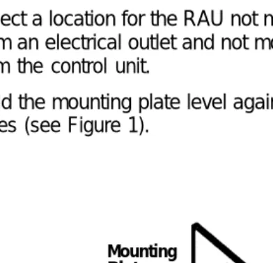
Select a location for the RAU not more than 1.8 m (6 feet) from an electrical outlet and not more than 1.8 m (6 feet) from the control unit.
Hold the mounting plate level against the wall, and mark the holes (see Figure 1).
Mounting Plate (use for markings)
Plastic
Wall
Mounting Screw Locations (Side view)
4.
5.
6.
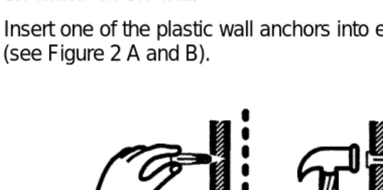
Drill a hole 4.7 mm (3/16 inch) in diameter through each of the marks on the wall.
Insert one of the plastic wall anchors into each of the holes (see Figure 2 A and B).
Screw Anchor
A B
Leave 3mm (1/8inch) of screw exposed (do not tighten flush to wall)
C
Figure 2. Inserting Anchors and Screws
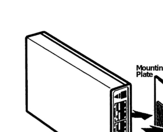
7. Place the mounting plate on the screws (see Figure 3).
Mounting Plate Wall
RAU Double-Sided
8.
9.
10.
Adhesive
Mounting Screw Locations (Side view)
Figure 3. Attaching the RAU and Mounting Plate with Adhesive
Attach the double-sided adhesive to the mounting plate (see Figure 3).
Hold the RAU so that the panel with the lights and jacks is easily visible. Then press the RAU against the double-sided adhesive on the mounting plate (see Figure 3).
Connecting the RAU
After wall mounting the RAU or placing it on a desk, do the follow-ing steps usfollow-ing Figure 4 as a guide:
Plug one of the 2-pair line cords into the system program-ming extension jack on the control unit. As noted previ-ously, this can be extension 10 or extension 11 (if the sys-tem allows programming from extension 11).
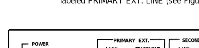
Plug the other end of the line cord into the leftmost RAU jack labeled PRIMARY EXT. LINE (see Figure 4).
POWER
PRIMARY EXT.
ACTIVE
R-RAU DTMF
CU-RAU PULSE
SECONDARY EXT.
LINE TELEPHONE LINE TELEPHONE POWER
Figure 4. RAU Front Panel
1.
2.
3.
4.
At this point, do one of the following:
■
■
If the user wishes to connect an MLS-CA24 Call Assistant™ Intercom Autodialer at this extension, connect the Autodialer to the RAU jack labeled PRl-MARY EXT. TELEPHONE. Then connect the system phone to the Autodialer.
If the user wishes to connect only a system phone at this extension, connect the phone to the RAU jack labeled PRIMARY EXT. TELEPHONE.
Move the R-RAU/CU-RAU sw”tch to the CU-RAU position. Disregard the DTMF/PULSE switch.
NOTE:
if you change the R-RAU/CU-RAU switch setting after the RAU is installed, you must unplug the RAU power supply from the wall outlet and plug it back in for the change to take effect.
5.
6.
7.
8.
9.
Plug one end of the power supply cord into the RAU jack labeled POWER.
Plug the other end of the power supply cord into the power supply.
Plug the power supply into a wall outlet. The light labeled POWER should be lit. If not, check all connections. The light labeled ACTIVE will be lit only during remote adminis-tration.
Continue with “Required Programming.”
Required Programming
Installing an RAU
at the Remote Location
The RAU is designed for use with any PARTNER communications system. However, the RAU can be connected directly to a loop-start Central Office line or behind a PBX analog extension port. If you wish to install an RAU at a location without a PARTNER sys-tem, contact the Central Office to be sure the location uses a loop-start line.
In addition to the RAU, you will need a system display phone:
■
■
an MLS-12D or MLS-18D is recommended for a remote location that administers only small PARTNER systems of up to 4 lines/12 extensions maximum;
an MLS-34D phone is recommended for a remote location
that administers PARTNER II or PARTNER Plus systems as
well as small PARTNER systems.
You also can connect an MLS-CA24 Call Assistant Intercom Autodialer.
Remote Location
without a PARTNER System
To install the RAU at a location where a PARTNER system is not installed, do the following:
1. Place the RAU on the remote system manager’s desk, or
mount the RAU on the wall next to the system phone so the manager can see the RAU panel lights. The RAU should be within 1.8 m (6 feet) of an electrical outlet.
NOTE:
Plug the loop-start line cord into the leftmost RAU jack labeled PRIMARY EXT. LINE (see Figure 5).
POWER PRIMARY EXT. SECONDARY EXT.
L I N E TELEPHONE L I N E TELEPHONE POWER
R-RAU DTMF
ACTIVE CU-RAU PULSE
2 .
3 .
4 .
5 .
Figure 5. RAU Front Panel
At this point, do one of the following:
■
■
If you wish to connect an MLS-CA24 Call Assistant Intercom Autodialer along with the system phone, connect the Autodialer to the RAU jack labeled PRl-MARY EXT. TELEPHONE. Then connect the system phone to the Autodialer.
NOTE:
The Autodialer will be operational only when the RAU is remotely administering a PARTNER system.
If you wish to connect only the system phone, con-nect the phone to the RAU jack labeled PRIMARY EXT. TELEPHONE.
Do not connect anything to the SECONDARY EXT. LINE or SECONDARY EXT. TELEPHONE jacks on the RAU.
6.
7.
8.
9.
NOTE:
If you change the R-RAU/CU-RAU switch setting after the RAU is installed, you must unplug the RAU power supply from the wall outlet and plug it back in for the change to take effect.
If the Ioop-start line supports touch-tone dialing, move the DTMF/PULSE switch to DTMF. If the line supports rotary dialing only, move the DTMF/PULSE switch to PULSE.
NOTE:
If you change the DTMF/PULSE switch setting after the RAU is installed, you must unplug the RAU power supply from the wall outlet and plug it back in for the change to take effect.
Plug one end of the power supply cord into the RAU jack labeled POWER.
Plug the other end of the power supply cord into the power supply.
Plug the power supply into a wall outlet. The light labeled POWER should be lit. if not, check all connections. The light labeled ACTIVE will be lit only during remote adminis-tration.
Telephone Operation and Use
Remote Location
with a PARTNER System
To install the RAU at a location with a PARTNER system, do the following:
1 .
2 .
3 .
Place the RAU on the remote system manager’s desk, or mount the RAU on the wall next to the system phone so the manager can see the RAU panel lights. Do not place the RAU on top of the PARTNER control unit or modules. The RAU should be within 1.8 m (6 feet) of an electrical outlet.
NOTE:
To wall mount the RAU, follow Steps 1 through 9 of “Wall Mounting the RAU” earlier in this chapter. Then continue with Step 2 below.
Plug one of the 2-pair line cords into any desired extension jack on the control unit.
Plug the other end of the line cord into the leftmost RAU jack labeled PRIMARY EXT. LINE.
POWER
R-RAU DTMF
ACTIVE CU-RAU PULSE
PRIMARY EXT.
LINE TELEPHONE
SECONDARY EXT.
LINE TELEPHONE POWER
4. 5. 6. 7. 8. 9.
At this point, do one of the following:
If you wish to connect an MLS-CA24 Call Assistant Intercom Autodialer at this extension along with the system phone, connect the Autodialer to the RAU jack labeled PRIMARY EXT. TELEPHONE. Then con-nect the system phone to the Autodialer.
NOTE:
The Autodialer will be operational only when the RAU is remotely administering a PARTNER system.
If you wish to connect only the system phone at this extension, connect the phone to the RAU jack labeled PRIMARY EXT. TELEPHONE.
Do not connect anything to the SECONDARY EXT. LINE or SECONDARY EXT. TELEPHONE jacks on the RAU.
Move the R-RAU/CU-RAU switch to the R-RAU position. Disregard the DTMF/PULSE switch.
NOTE:
If you change the R-RAU/CU-RAU switch setting after the RAU is installed, you must unplug the RAU power supply from the wall outlet and plug it back in for the change to take effect.
Plug one end of the power supply cord into the RAU jack labeled POWER.
Plug the other end of the power supply cord into the power supply.
Plug the power supply into a wall outlet. The light labeled POWER should be lit. If not, check all connections. The light labeled ACTIVE will be lit only during remote adminis-tration.
■
10. At the system phone connected to this RAU, press [ Feature ]
[ ✳ ] [ 9 ] while the handset is in the cradle. This initializes the
RAU. You do not receive any signal from the RAU that ini-tialization has taken place.
Allowing Remote
Administration
2
Contents
When You Call the Remote Location 2-2
When the Remote Location Calls You 2-3
When Remote Administration Occurs
After Hours 2-3
Security of Your System 2-4
Enabling Unattended Administration 2-5
Disabling Unattended Administration 2-6
■
■
Allowing Remote
Administration
2
Read this chapter if you wish to allow remote administration of your PARTNER system. Remote administration allows a remote system manager or Service Center associate to perform system programming from a remote location.
Remote administration requires the following:
■
■
■
A Remote Administration Unit (RAU) must be installed near the system control unit.
The system phone at extension 10 or 11 must be connected to the RAU jack labeled PRIMARY EXT. TELEPHONE instead of being connected directly to the control unit. Throughout the remainder of this chapter, this phone will be called the Primary Extension Telephone. During remote administration, this phone is unavailable to make or answer calls.
Automatic Extension Privacy, if available on your
system, must be assigned to the extension connected to the RAU. For more information on Automatic Extension
Privacy, see the programming instructions in the
Throughout the remainder of this chapter, remote system
manager refers to the remote system manager or Service Center associate, and remote location refers to the Service Center or other remote location.
Remote administration can be initiated in one of three ways:
■
■
■
You can call the remote location and request assistance.
The remote location can call you and request permission to administer your system.
You can set the system to allow remote administration after normal business hours or when the system is unattended.
CAUTION:
Please carefully read the section “Security of Your System” on page 2-4 for information on how to better protect your system.
When You Call
the Remote Location
To request remote programming for your system:
1.
2.
3.
Place a call from your Primary Extension Telephone to the remote system manager at the remote location.
When the remote system manager tells you to do so, start the remote administration by pressing [ Feature ] [ ✳ ] [ ✳ ]. At this point, you will no longer hear the remote system manager’s voice. As the remote system manager performs remote program-ming, the associated messages appear on your Primary Exten-sion Telephone’s display (if you have a system display phone).
When the Remote Location
Calls You
If the remote location calls you to request permission to adminis-ter your system, do the following:
1.
2.
3.
Be sure the call is at your Primary Extension Telephone. If it is not, transfer the call to the correct extension.
When the remote system manager tells you to do so, start the remote administration by pressing [ Feature ] [ ✳ ] [ ✳ ]. At this point, you will no longer hear the remote system manager’s voice. As the remote system manager performs remote program-ming, the associated messages appear on your Primary Exten-sion Telephone display (if you have a system display phone).
Remain on the line using the speakerphone (or listening through the handset) so you can speak with the remote sys-tem manager when the remote administration is completed.
When Remote Administration
Occurs After Hours
Security of Your System
CAUTION:
As a customer of a Remote Administration Unit, you should be aware that there exists an increasing problem of tele-phone toll fraud. Teletele-phone toll fraud can occur in many forms, despite the numerous efforts of telephone companies and telephone equipment manufacturers to control it.
The following security measures assist you in managing remote administration to help prevent unauthorized use:
■
■
■
Always enter a four-digit password for unattended administration. Use a different password each time.
Immediately after enabling unattended administration, notify the remote system manager.
Enabling Unattended Administration
To enable unattended administration, do the following:
If answering machines are connected to the line on which the remote system manager will call, turn them off or disconnect them.
1.
2.
3.
4.
5.
If you have voice mail coverage on your Primary Extension Telephone, turn it off to prevent the voice mail from answer-ing the remote system manager’s call.
At the Primary Extension Telephone, press [ Feature ] [ ✳ ] [ 1 ].
It is not necessary to lift the handset or to press [ Spkr ].
To enter a password, dial four digits of your choice.
NOTE:
It is strongly recommended that you enter a four-digit pass-word. If you enter a password, the remote system manager must enter that same password to administer your system. When you disable unattended administration, the password is automatically erased. You may select a different pass-word each time you enable unattended administration.
Notify the remote system manager that unattended adminis-tration has been enabled. If you entered a password, tell it to the remote system manager.
NOTE:
Disabling Unattended Administration
It is recommended that you disable unattended administration as soon as possible (typically the morning after remote administra-tion has been performed).
To disable unattended administration, press [ Feature ] [ ✳ ] [ 0 ] at
Performing Remote
Administration
3
Contents
Initializing Attended Administration 3-1 Initializing Unattended Administration 3-2 Remote Programming 3-4 Power Failure at the Remote Location 3-5 Summary of Remote Administration
Performing Remote
Administration
3
Read this chapter if you are a remote system manager or a Service Center associate who wishes to perform remote programming.
Initializing Attended
Administration
Remote administration may begin when the local site calls you for assistance, or when you call the local site and request permission to administer the system. In either case, once you are talking with the user at the local site, do the following:
1.
2.
Continue this call using the handset (not the speakerphone) of the phone connected to your RAU.
Ask the user to allow remote administration by pressing [ Feature ] [ ✳ ] [ ✳ ].
At this point, the RAU modem will try to establish a connection at 2400 bps. If that connection cannot be made, the modem will attempt a connection at 1200 bps:
■
■
■
If the connection is established at 2400 bps, the display at your phone is:
****
If the connection is established at 1200 bps, the display at your phone is:
***!
When the modem connection is made, the ACTIVE light on the RAU is lit.
If a modem connection cannot be made at all, the voice connection is resumed, and you can ask the user to press [ Feature ] [ ✳ ] [ ✳ ] again.
When you receive one of the modem connection displays, you are at the Main Level of remote administration commands and you can begin remote programming.
Initializing Unattended
Administration
If the local site has enabled unattended administration as described in Chapter 2, you can call the local site’s system directly, following the steps below.
1. Using the handset (not the speakerphone) of the phone connected to your RAU, place a call to the Primary Exten-sion Telephone at the local site.
2.
3.
If the user at the local site specified a password for unat-tended administration, you are prompted to enter the pass-word when the modem connection has been established. The display reads:
????
Slowly enter the four-digit password.
At this point, one of the following happens:
If the connection is established at 2400 bps, the display at your phone is:
■
■
■
* * * *
If the connection is established at 1200 bps, the display at your phone is:
* * * !
When the modem connection is made, the ACTIVE light on the RAU is lit.
If you entered the password incorrectly, the phone
beeps and the password prompt (????) is
displayed again. You can try to re-enter the pass-word three times before the connection is dropped.
Remote Programming
Any programming that can be performed on a system phone at extension 10 or 11 at the local site can be performed by the remote system manager at the remote location. See the appropriate PARTNER system Programming and Use guide for information on specific programming procedures.
1. 2. 3. 4. 5. 6. 7.
Press [ Feature ] [ ✳ ] [ 2 ] to enter remote programming mode. The modem connection is verified and remains established dur-ing remote administration. The lights on your phone indicate the status of the corresponding buttons on the Primary Extension Telephone at the local site.
Press [ Feature ] [ 0 ] [ 0 ] left [ Intercom ] left [ Intercom ] to enter
pro-gramming mode.
If a System Programming Password is required by your sys-tem, enter it.
Press right [ Intercom ] to enter Centralized Telephone
Pro-gramming, or enter [ ✳ ] and a three-digit programming pro-cedure code for system programming.
Continue programming as described in the Programming and Use guide.
Press [ Feature ] [ 0 ] [ 0 ] to exit programming mode.
At this point, do one of the following:
■
■
■
Press [ Feature ] [ ✳ ] [ 6 ] to return to the Main Level of
remote administration commands.
Press [ Feature ] [ ✳ ] [ 3 ] to drop the modem connection
and resume the original voice connection with the user at the local site.
Power Failure
at the Remote Location
If a power failure occurs at the remote location where the RAU is connected to a PARTNER system control unit, you may need to reset the RAU and the control unit. If the red light next to the left intercom button on the system phone connected to the RAU is lit after power has been restored, reset the RAU and the control unit by pressing [ Feature ] [ ✳ ] [ 9 ].
The red light next to the left intercom button goes out, and the phone lights reflect the status of the buttons.
Summary of Remote Administration Commands
Command Function
[ Feature ] [ ✳ ] [ ✳ ] Start remote administration [ Feature ] [ ✳ ] [ 0 ] Disable unattended administration [ Feature ] [ ✳ ] [ 1 ] Enable unattended administration
+ 4-digit password
[ Feature ] [ ✳ ] [ 2 ] Enter remote programming mode
[ Feature ] [ ✳ ] [ 3 ] Re-establish voice connection with local site
[ Feature ] [ ✳ ] [ 6 ] Return to Main Level of remote administration
commands
[ Feature ] [ ✳ ] [ 9 ] Initialize RAU (after installation or power failure)
Glossary
L
Local site
Place with installed PARTNER, PARTNER Plus, or PARTNER II system that can be administered remotely.
P
Primary Extension Telephone
The phone connected to the RAU jack labeled PRIMARY EXT. TELEPHONE.
R
Remote Administration
Function that allows programming of a PARTNER, PARTNER Plus, or PARTNER II system from a location other than the one where the system is installed.
Remote location
Place other than the one where the PARTNER, PARTNER Plus, or PARTNER
II system is installed.
Remote system manager
Glossary
S
Service Center associate
AT&T employee or Authorized Distributor who can perform programming on PARTNER, PARTNER Plus, and PARTNER II systems.
Standard phones
Industry-standard touch-tone or rotary telephones, which can be used with the system.
System
The PARTNER, PARTNER Plus, or PARTNER II Communications System control unit and system phones that you purchased, plus all other telecommunications devices that are connected to the control unit.
System phones
The AT&T telephones that are specifically designed to work with your PARTNER system. Models include the MLS-34D, MLS-18D, MLS-12D, MLS-12, MLS-6, and MLC-6 telephones.
U
Unattended Administration
Index
A
Active light, 1-6, 1-7, 1-10, 1-11, 1-12
Answering machines, with unattended administration, 2-5 Attended administration
for remote system manager, 3-1 – 3-2
for user at local site, 2-3 Autodialer, 1-6, 1-8, 1-9, 1-12 Automatic Extension Privacy,
1-7, 2-1
C
Call Assistant (see Autodialer) Centralized Telephone
Programming, 3-4
Commands, summary of remote administration, 3-6
Components (see RAU components)
D
DTMF/Pulse switch, 1-7, 1-10, 1-12
E
Extension 10, 1-2 Extension 11, 1-2
I
Initializing an RAU, 1-13, 3-6 Installing an RAU
at the local site, 1-2 – 1-7 at a remote location with a PARTNER system, 1-11 – 1-13 at a remote location without a PARTNER system, 1-8 – 1-10 Intercom Autodialer (see
Autodialer)
L
Line cords (see Telephone line cords)
Loop-start line, 1-8, 1-10
M
MLS-CA24 Call Assistant (see Autodialer)
Modem, 3-1 – 3-3
Index
P
Password, for remote admin-istration, 2-4, 2-5, 2-6, 3-3 PBX analog extension port, 1-8 Power failure, 1-13, 3-5, 3-6 Power light, 1-6, 1-7, 1-10, 1-11,
1-12
Power supply, 1-2, 1-7, 1-10, 1-12
Primary Extension Telephone, 2-1, 2-2, 2-3, 2-5, 2-6 PRIMARY EXT. LINE jack, 1-6,
1-9, 1-11
PRIMARY EXT. TELEPHONE jack, 1-6, 1-9, 1-11
Programming (see also Remote programming), 1-7, 2-1 Programming mode, 3-4
R
RAU components, 1-2 Remote administration, how to
request, 2-2
Remote location, 1-1, 2-2 Remote programming, 1-1, 2-1,
3-4, 3-6
Remote system manager, 1-1, 2-2
R-RAU/CU-RAU switch, 1-7, 1-9, 1-10, 1-12
S
SECONDARY EXT. LINE jack, 1-6, 1-9, 1-12
SECONDARY EXT. TELEPHONE jack, 1-6, 1-9, 1-12
Security of your system, 2-4 Service Center, 1-1, 2-2 Standard phone, iv
System phone, iv, 1-8, 1-10, 1-12, 2-1
System programming (see Remote programming) System Programming
Password, 3-4
T
Telephone line cords, 1-2, 1-6, 1-9, 1-11
U
Unattended administration defined, 2-3
disabling, 2-6, 3-6 enabling, 2-5, 3-6
for remote system manager, 3-2 – 3-3
Index
V