(SINTESIS DAN PENGUBAHSUAIAN BAHAN MIKRO AND MESOPOROS SEBAGAI BAHAN PENJERAP CO2)
KHAIRUL SOZANA NOR KAMARUDIN HANAPI MAT
FAKULTI KEJURUTERAAN KIMIA DAN KEJURUTERAAN SUMBER ASLI
ACKNOWLEDGEMENT
ABSTRACT
SYNTHESIS AND MODIFICATION OF MICRO AND MESOPOROUS MATERIALS AS CO2 ADSORBENTS
(Keyword: Microporous, Mesoporous, Zeolite, Amines, CO2 adsorption)
Key Researchers:
Dr. Khairul Sozana Nor Binti Kamarudin Associate Professor Dr. Hanapi Bin Mat
Chua Chung Lieh Siti Syahida Binti Mohd Yassin
Mohd Hanafi Bin Abd. Rahim Nur Hashimah Binti Alias
ABSTRAK
SINTESIS DAN PENGUBAHSUAIAN BAHAN MIKRO AND MESOPOROS SEBAGAI BAHAN PENJERAP CO2
(Kata kunci: Mikroporos, Mesoporos, Zeolite, Amin, Penjerapan CO2)
Penyelidik Utama:
Dr. Khairul Sozana Nor Binti Kamarudin Associate Professor Dr. Hanapi Bin Mat
Chua Chung Lieh Siti Syahida Binti Mohd Yassin
Mohd Hanafi Bin Abd. Rahim Nur Hashimah Binti Alias
TABLE OF CONTENTS
CHAPTER TITLE PAGE
TITLE PAGE i
ACKNOWLEDGEMENT ii
ABSTRACT iii
ABSTRAK v
TABLE OF CONTENTS vii
LIST OF TABLES xii
LIST OF FIGURES xiii
LIST OF SYMBOLS xviii
LIST OF ABBREVIATIONS xix
LIST OF APPENDICES xx
1 INTRODUCTION 1
1.1 Introduction to CO2 Adsorption 1
1.2 Research Background 4
1.3 Objectives and Scopes of Study 6
1.4 Report Outline 7
1.5 Summary 8
2 LITERATURE REVIEW
2.1.1 Fundamental of Natural Gas 10
2.1.2 Uses of Natural Gases 11
2.1.3 Natural Gas Processing 14
2.1.4 Carbon Dioxide Removal from Natural Gas 15 2.1.4.1 Adsorption as a Method for CO2 Removal 16 2.1.4.2 Adsorbent for CO2 Removal 17 2.1.4.3 Amine Solutions as Carbon Dioxide
Removal System 18
2.2 Adsorption Process 19
2.2.1 Adsorption Concept 20
2.2.2 Types of Adsorption 21
2.2.2.1 Ion Exchange 21
2.2.2.2 Physisorption 22
2.2.2.3 Chemisorption 23
2.2.3 Adsorption Isotherms 21
2.2.4 Adsorption Mechanism by Porous Adsorbents 27 2.2.4.1 Physisorption by Microporous Adsorbents 27 2.2.4.2 Physisorption by Mesoporous Adsorbents 28 2.2.5 Adsorption Controlling Parameters 31
2.3 Adsorbents 32
2.3.1 Microporous Materials 33
2.3.1.1 Classification of Zeolites 34 2.3.1.2 Structure and Framework of Zeolites 36 2.3.2 Mesoporous Materials 37 2.3.2.1 Formation Mechanism of Mesoporous
2.3.2.2 Types of Mesoporous Materials 41 2.3.2.3 Application of Mesoporous Materials 44 2.3.3 Modification of Porous Materials 45
2.4 Summary 47
3 MATERIALS AND METHODS 49
3.1 Materials 49
3.1.1 Chemicals 49
3.1.2 Zeolites 50
3.1.3 Metal nitrates 50
3.1.4 Gases 51
3.2 Experimental Procedures 51
3.2.1 Preparation of Adsorbents 51 3.2.1.1 MCM-41 Preparation 53 3.2.1.2 SBA-15 Preparation 53 3.2.1.3 Metal modified MCM-41 54 3.2.2 Preparation of Modified Adsorbents 55
3.2.3 Characterization 56
3.2.3.1 Structural Characterization 56 3.2.3.2 Physical Properties Characterization 56 3.2.4 Gas Adsorption Measurement 57 3.2.4.1 Thermal Gravimetric Analyzer (TGA) 57 3.2.4.2 Fourier Transform Infrared
3.3 Summary 60
4 RESULTS AND DISCUSSIONS 62
4.1 Introduction 62
4.2 Structural Characteristics and Properties 63 4.2.1 Effects of Various Amines 63 4.2.2 Effects of Metals Loading 71 4.2.3 Effects of Amine on Microporous Materials 73 4.2.4 Effects of Amine Concentrations 76
4.3 Carbon Dioxide Adsorption Characteristics 78 4.3.1 Effects of Various Amines 78 4.3.2 Effects of Amine Concentrations 88 4.3.3 Effects of Support Materials 92 4.3.4 Influence of Operating Temperature 97 4.3.4.1 Influence of Adsorption Temperatures 98 4.3.4.2 Influence of Heating Temperatures 100
4.4 Gas-Solid Interaction 104
4.4.1 Interaction of CO2 on Various Amines
Modified MCM-41 105
4.4.2 Interaction of CO2 on MEA Modified
MCM-41 at Various Pressures 108
5 CONCLUSIONS AND RECOMMENDATIONS 113
5.1 Introduction 113
5.2 Summary of Research Findings 114
5.3 Recommendations for Future Work 117
5.4 Concluding Remarks 117
REFERENCES 118
LIST OF TABLES
TABLE NO. TITLE
PAGE
2.1 Typical composition of natural gas 10
3.1 General chemicals for the synthesis of mesoporous adsorbents 50
4.1 Summary of N2 adsorption properties for MCM-41 and amine 67 modified MCM-41
4.2 Physical properties of metal oxides 72
4.3 Structural characterization of metal oxide modified Na-Y zeolites 76
4.4 CO2 uptake rate, R and equilibrium adsorption time requirement for different amines modified MCM-41 88
4.5 CO2 uptake rate and equilibrium adsorption time requirement for MEA modified MCM-41 at different concentrations 91
4.6 CO2 uptake rate and equilibrium adsorption time requirement for
LIST OF FIGURES
FIGURE NO. TITLE
PAGE
2.1 Total sources of energy consumed in U.S. for 2000 12
2.2 Natural gas use by sector 13
2.3 Schematic view of cryogenic heat exchanger showing the
manifolds (6) and nozzles (7) 15
2.4 IUPAC classification of adsorption isotherms. 25
2.5 A 5-1 secondary building unit and the MFI structure. 35
2.6 Structures of four selected zeolites (from top to bottom: faujasite or zeolites X, Y; zeolite ZSM-12; zeolite ZSM-5 or silicalite-1; zeolite Theta-1 or ZSM-22) and their micropore systems and
dimensions. 37
2.8 Possible mechanistic pathways for the formation of MCM-41:
(1) liquid crystal initiated and (2) silicate anion initiated. 41
2.9 The X-ray diffraction patterns and proposed structures of
MCM-41, MCM-48, and MCM-50. 43
2.10 Transmission electron micrographs of MCM-41 materials
with pore sizes of 20, 40, 60, and 100 Å. 43
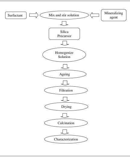
3.1 General experimental flow sheet. 52
3.2 The schematic diagram of in situ FTIR cell. 59
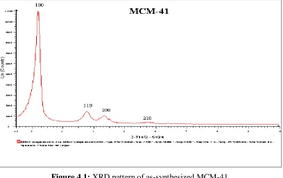
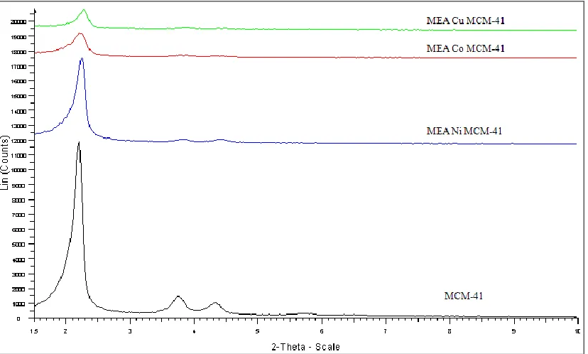
4.1 XRD pattern of as-synthesized MCM-41. 64
4.2 XRD patterns of different amines grafted on MCM-41. (PEI= polyethylenimine, MDEA= methyl diethanolamine, TEA= triethanolamine, DEA= diethanolamine, and
MEA= monoethanolamine) 65
4.3 Nitrogen adsorption isotherm of MCM-41 and 20 wt%
MEA/MCM-41. 66
4.4 FTIR spectra of MCM-41. 68
4.5 FTIR spectra of amines modified MCM-41. 70
4.6 XRD patterns of MCM-41 and 0.5 wt% 0f different metals
4.7 XRD patterns of 20wt% MEA grafted on different metals
modified MCM-41. 73
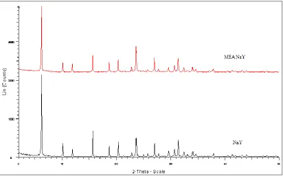
4.8 XRD patterns of zeolite NaY and MEA modified NaY. 74
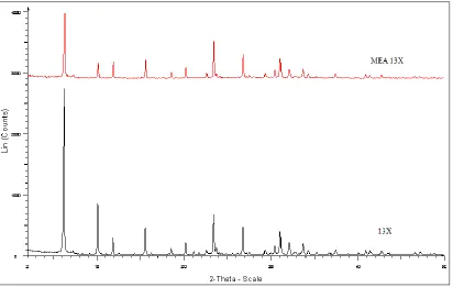
4.9 XRD patterns of zeolite 13X and MEA modified 13X. 75
4.10 The effect of MEA loadings on the diffraction intensity of
the (100) plane of MCM-41. 77
4.11 Surface reactions of amine groups with CO2. 81
4.12 Gas CO2 adsorption capacity for MCM-41 support and
amines modified MCM-41. 82
4.13 Comparison of BET surface area and gas CO2 adsorption
capacity for MCM-41 support and amines modified MCM-41. 84
4.14 R represents the slope of CO2 uptake for MCM-41 and amine
modified MCM-41. 86
4.15 CO2 adsorption capacity for MCM-41 and amine modified
MCM-41. 87
4.16 Gas CO2 adsorption capacity for MEA modified MCM-41 at
different concentrations. 89
4.17 CO2 adsorption capacity for MEA modified MCM-41 at
4.18 Gas CO2 adsorption capacity for various mesoporous and
microporous supports and MEA modified supports. 94
4.19 TGA curves of CO2 adsorption capacity for MEA modified
mesoporous and microporous supports. 96
4.20 Gas CO2 adsorption capacity for 20 wt% MEA modified
MCM-41 at different adsorption temperatures. 99
4.21 Slope, R represent rate of CO2 uptake for 20 wt% MEA
modified MCM-41 at different adsorption temperatures. 100
4.22 Gas CO2 adsorption capacity for 20 wt% MEA modified
MCM-41 at different heating temperatures. 102
4.23 Slope, R represent rate of CO2 uptake for 20 wt% MEA
modified MCM-41 at different heating temperatures. 103
4.24 FTIR spectra of CO2 adsorbed on: (a) MCM-41; (b) 20 wt% MEA/MCM-41; (c) 20 wt% DEA/MCM-41; (d) 20 wt% TEA/MCM-41; (e) 20 wt% MDEA/MCM-41; and (f) 20 wt%
PEI/MCM-41 at equilibrium pressures of 138 kPa and 25˚C. 105
4.25 The corresponding areas of the FTIR spectrum peak at (1520 – 1420 cm-1 region) versus the amount of CO
2 adsorbed
on amine modified MCM-41. 107
4.26 Schematic diagram of CO2 adsorption on amine modified
4.27 FTIR spectra of CO2 adsorbed on MEA modified MCM-41 at 25˚C and equilibrium pressure: (a) without CO2; (b) 138 kPa;
(c) 276 kPa; (d) 414 kPa and (e) 552 kPa. 109
4.28 Effect of equilibrium CO2 pressure on the FTIR absorbance areas
(2420 – 2380 cm-1 region) for the physisorption peak. 110
4.29 Effect of equilibrium CO2 pressure on the FTIR absorbance
LIST OF SYMBOLS
0 C - Degree Celsius
T - Temperature (K)
d - Spacing of indices planes
h - Miller indices planes
k - Miller indices planes
l - Miller indices planes
% - Percentage
θ - Angle
λ - Wavelength
Irel - Relative Intensity
wt. - Weight
Å - Angstrom (1Å = 10-10 m)
A - Absorbance
LIST OF ABBREVIATIONS
FTIR - Fourier Transform Infrared Spectroscopy
US - United State
BET - Brunauer, Emmett, Teller XRD - X-Ray Diffraction
SEM - Scanning Electron Microscope TEM - Transmission Electron Microscope TGA - Thermogravimetric Analyzer MEA - Monoethanolamine
DEA - Diethanolamine TEA - Triethanolamine
LIST OF APPENDICES
APPENDIX TITLE PAGE
A Calculation of amines 130
CHAPTER 1
INTRODUCTION
1.1 Introduction to CO2 Adsorption
Malaysia has a vast reserve of natural gas, which places the country as the 13th largest gas reserves in the world in year 2001 (Anon,2005). As at 31 December 2003, Malaysia‟s gas reserves stood at 89.02 trillion standard cubic feet. At the current
production rate, the gas reserve is estimated to last another 50 years (Anon, 2005). Recently, Malaysia is increasingly turning to natural gas from oil, not only as a source of energy, but also as a raw material in the manufacture of various petrochemical products. Natural Gas for Vehicle (NGV) program has diversified the use of natural gas into a new era.
produce good quality gas (Daiminger, 2004). Carbon dioxide removal from natural gas attracts more attention than other impurities due to its corrosiveness and inert property. Up to date, the capture and separation of CO2 can be achieved by different approaches,
namely chemical and physical absorption using solvents, solid physical adsorption, cryogenic techniques and membrane separation (Gray et al., 2004; Meisen and Shuai,
1997). Among the approaches used, amine based chemical absorption have been used commercially for CO2 capturing plant. However, the liquid amine based processes pose
operating difficulties due to the challenge of keeping the solvent clean and operating within the process constraints of the system (Daiminger, 2004). Besides, this process also suffers from high regeneration energy, large equipment size, solvent leakage from piping system and also equipment corrosion problem (Xu et al., 2005). Therefore, many researchers have switched the work to another promising method, which is adsorption process due to its low energy requirement, cost advantage and ease of applicability over a relatively wide range of temperatures and pressures (Xu et al., 2003; Xu et al., 2005). Developing an adsorbent with high CO2 adsorption capacity and high selectivity has
now become the major challenge in the research of adsorption separation.
The discovery of zeolites by the Swedish scientist Cronstedt in 1756 until the introduction of synthetic zeolites in 1954 by Union Carbide as a new class of industrial adsorbents has proved the versatility of zeolites as good molecular sieve (Ghobarkar et
al., 1999). Besides, zeolites also possess large internal pore volumes, molecular-size pores, regularity of crystal structures and diverse framework chemical composition, which enable them to be tailor-made into different structure and properties. Therefore, zeolites have been widely investigated as adsorbents for carbon dioxide separation (Sherman, 1999; Weitkamp, 2000; Ghobarkar et al., 1999).
mesoporous adsorbents by scientists at Mobil Oil (Zhao et al., 1996; Kumar et al., 2001; Kresge et al., 1992). Among the M41S family, the two most investigated materials are the MCM-41 with a 2-D hexagonal structure and the MCM-48 with a 3-D cubic structure (Kumar et al., 2001). These highly ordered pore systems with tunable pore sizes, large specific surface areas and pore volumes, and high density of surface silanols
provide excellent opportunities in inclusion chemistry. A large number of functionalizing entities including both organic and inorganic ligands have been introduced in the channels to generate catalysts, adsorbents, and to improve the hydrothermal and mechanical stabilities (Zhao et al., 1996; Zhao et al., 2000).
Discovery of the M41S family of molecular sieves has led to significant progress in the synthesis and characterization of ordered mesoporous materials. Large pore-size molecular sieves are much in demand for reactions or separations and the development of mesoporous structure has resulted in the preparation of well-ordered hexagonal mesoporous silica structures (SBA-15) with uniform pore sized up to approximately 300 angstroms (Stucky et al., 1998). SBA-15 which is a polymer-templated silica with hexagonally ordered mesopores has larger pore size, thicker pore walls and higher hydrothermal stability in comparison to MCM-41, which is surfactant-templated ordered mesoporous material.
The polymer employ to obtain SBA-15, poly(ethylene oxide)-poly(propylene oxide)-poly(ethylene oxide) (PEO-PPO-PEO), is biodegradable and cheaper than the surfactant used in the synthesis of MCM-41 (Fulvio et al., 2005). Another feature of SBA-15 is the existence of micropores interconnecting hexagonally ordered mesopores, which make it more suitable for catalysis because these interconnections facilitate diffusion inside the entire porous structure (Tatiana Klimova et al., 2006; Fulvio et al., 2005). These ordered structure with various pore sizes characteristic are suitable for either microporous or mesoporous materials to be use as support materials in
Physical sorbents such as zeolites and carbon molecular sieves can reversibly adsorb a large quantity of CO2 at room temperature. However, their capacity diminishes
quickly at elevated temperature and the selectivity over water is poor. Amine functional groups are useful for CO2 removal because of their ability to form ammonium
carbamates and carbonates reversibly at moderate temperature (Gray et al., 2005). The
incorporation of organic amines into a porous support is a promising approach for CO2
sorbents combining good capacity and selectivity at moderate temperature (Zheng et al., 2005; Xu et al., 2002; Xu et al., 2003; Khatri et al., 2005).
Recently, the latest development of zeolites has been proposed with their new concept of CO2 “molecular basket” for developing high-capacity, highly-selective CO2
adsorbents, which can be operated at elevated temperature (Xu et al., 2003). This novel CO2 “molecular basket” adsorbents are developed based on polyethyleimine
(PEI)-modified mesoporous molecular sieve of MCM-41 type and shows high CO2 adsorption
capacity, which is 30 times higher than MCM-41 and more than twice of the pure PEI (Xu et al., 2003). Therefore, the proposed research will use the above mentioned concept to develop new amine modified porous materials as CO2 adsorbents. Different
alkanolamines including primary, secondary and tertiary amines will be used as the amine source and incorporated onto different type of support materials.
1.2 Research Background
Current technologies deploy at commercial scale for CO2 removal use processes
energy, large equipment size, solvent degradation and equipment corrosion (Xu et al., 2005).
To overcome these disadvantages, several other separation technologies, such as
adsorption, membrane and cryogenic separation have been studied. Over all the technologies, adsorption separation attracts more interest because of the low energy requirement, cost advantage, and ease of applicability over a relatively wide range of temperature and pressure. Therefore, regenerable solid sorbents will be a promising alternative that can potentially offer several advantages over liquid amine systems such as ease in handling of solids, reduced toxicity and corrosiveness (Rajesh et al., 2005). Besides that, regenerable solid CO2 sorbents are also favorable for applications in
enclosed environments, such as submarines and spacecraft.
Various porous supports impregnated with liquid amines have been reported and such hybrid sorbents have been used successfully onboard space vehicles for crew air scrubbing (Zheng et al., 2005). However, loss of amine components due to evaporation is a problem at moderate temperature. By grafting of amine functional groups directly to the surface of a physical sorbent, the evaporation problem can be eliminated and the overall thermal stability can be improved (Khatri et al., 2005; Xu et al., 2002). The key
issue for adsorption separation is to develop an adsorbent with high CO2 adsorption
1.3 Objectives and Scopes of Study
Several objectives have been specified in this research including synthesis of amine-modified adsorbents for carbon dioxide adsorption, the characterization of the
physical and chemical properties of the synthesized adsorbents and the study of the carbon dioxide adsorption and desorption capacity. To be specific, two main objectives of this research are to study the effects of different type of amines on the adsorbents and the effects of different supporting materials, mesoporous materials and microporous materials by using one specific amine as standard (which is monoethanolamine, MEA) on the performance of carbon dioxide adsorption.
The main scopes in this research work is to achieve the specified objectives comprises of research activities such as preparation and modification of the adsorbents, the characterization of the adsorbents and the adsorption capacity study specifically for carbon dioxide separation. Two types of mesoporous adsorbents will be synthesis in this study as the supporting materials are MCM-41 and SBA-15. Meanwhile, other support materials such as zeolite NaY and 13X are obtained commercially.
After preparation of the support materials, the modification step is implemented by loading different types of amine groups into the adsorbents using freeze drying method. The characterization of chemical and physical properties of modified adsorbents such as the structure properties, the pore diameter distribution, the pore volume as well as the surface area are determined by X-ray diffraction (XRD) and N2
Other than adsorption capacity study, the modified adsorbents that have a good physical and chemical properties as well as adsorption properties such as good structure and high adsorption capacity is used as the standard adsorbent for the study of other parameters by varying amine concentration, adsorption temperatures, heating temperatures and carbon dioxide gas pressure for in situ adsorption study.
1.4 Report Outline
This thesis consists of five chapters which describes the research in a sequential order. Chapter 1 introduces the research background on amine modified adsorbents, problems encountered by the industry, and underlined objectives to solve the problems. Chapter 2 provides the literature review of the general aspects related to the field of research study. This includes natural gas processing, adsorption isotherms and mechanism, fundamental of microporous and mesoporous materials, modification of adsorbents and gas adsorption characteristics. Chapter 3 describes the materials and methods applied in the experimental study and adsorbents characterization in detail while the results and discussion of the findings are included in Chapter 4. Lastly,
1.5 Summary
Ordered mesoporous and microporous materials on its own may have high performance as catalysts or as highly selective adsorbents. The modification of these
adsorbents using different type of amines will create a combination of various physicochemical properties to produces more advance materials in many fields with additional functionality. Through this study, carbon dioxideadsorptive characteristics of amine modified adsorbents are well study and explain thoroughly for clear
understanding. The fundamental results and findings obtained will enable researchers to carry on the work to design new gas adsorbents with higher adsorption capacity,
CHAPTER 2
LITERATURE REVIEW
2.1 Introduction to Natural Gas
Natural gas is nothing new. In fact, most of the natural gas that is brought out from under the ground is millions and millions of years old. However, it was not until recently that methods for obtaining this gas, bringing it to the surface, and putting it to
use were developed.
2.1.1 Fundamental of Natural Gas
Natural gas is a combustible mixture of hydrocarbon gases. While natural gas is formed primarily of methane, it can also include ethane, propane, butane and pentane.
The composition of natural gas can vary widely, below is a chart outlining the typical makeup of natural gas before it is refined. From Table 2.1, it is clearly shows that carbon dioxide is the highest impurities (up to 8%) compare to others. Since the
presence of carbon dioxide tend to cause corrosive and inert property problem, therefore it is necessary to remove this unwanted gas.
Table 2.1: Typical composition of natural gas (Anon, 2005).
Composition Molecule Formula Percentage
Methane CH4 70 – 90%
Ethane C2H6
0 – 20%
Propane C3H8
Butane C4H10
Carbon Dioxide CO2 0 – 8%
Oxygen O2 0 – 0.2%
Nitrogen N2 0 – 5%
Hydrogen Sulphide H2S 0 – 5%
Rare Gases A, He, Ne, Xe trace
In its purest form, such as the natural gas used in Natural Gas Vehicles (NGV), it is almost pure methane. Methane is a molecule made up of one carbon atom and four
hydrogen atoms, and is referred to as CH4. Ethane, propane, and the other hydrocarbons
Natural gas is considered 'dry' when it is almost pure methane, having had most of the other commonly associated hydrocarbons removed. When other hydrocarbons are present, the natural gas is considered 'wet' gas.
Natural gas has many uses, residentially, commercially, and industrially. Natural gas can be found in reservoirs underneath the earth and is commonly associated with oil deposits. Production companies search for evidence of these reservoirs by using
sophisticated technology that helps to find the location of the natural gas, and drill wells in the earth where it is likely to be found. Once brought from underground, the natural gas is refined to remove impurities like water, other gases, sand, and other compounds. Some hydrocarbons are removed and sold separately, including propane and butane. Other impurities are also removed, like hydrogen sulfide (the refining of which can produce sulfur, which is then also sold separately). After refining, the clean natural gas is transmitted through a network of pipelines. From these pipelines, natural gas is delivered to its point of use.
2.1.2 Uses of Natural Gases
There are so many different applications for the fossil fuel that it is hard to provide a complete list of everything it is used for. New uses are being discovered all time and in a wide range of area. Natural gas has many applications, commercially, for household, in industry, and even in the transportation sector. While the uses described in Figure 2.1 are not extensive, it may help to show just how much useful natural gas can
be.
Figure 2.1: Total sources of energy consumed in U.S. for 2000 (Source: EIA - Annual Energy Outlook 2002).
According to the Energy Information Administration, energy from natural gas accounts for 24 percent of total energy consumed in the United States, making it a vital component of the nation's energy supply. Natural gas is used across all sectors, in
varying amounts. Figure 2.2 gives an idea of the proportion of natural gas use per sector. The industrial sector accounts for the greatest proportion of natural gas use in the United States, with the residential sector consuming the second greatest quantity of natural gas.
cannot be deny that the application of natural gas in a wide range of areas is increasing gradually in the Asian region especially in transportation. Therefore, there is a necessity to continually developing new and improve method of natural gas processing.
Figure 2.2: Natural gas use by sector (Source: EIA - Annual Energy Outlook 2002).
Natural gas has long been considered an alternative fuel for the transportation sector. In fact, natural gas has been used to fuel vehicles since the 1930's. According to the Natural Gas Vehicle Coalition, there are currently 130,000 Natural Gas Vehicles (NGVs) on the road in the United States today, and more than 2.5 million NGVs worldwide. In fact, the transportation sector accounts for 3 percent of all natural gas used in the United States. In recent years, technology has improved to allow for a proliferation of natural gas vehicles, particularly for fuel intensive vehicle fleets, such as taxicabs and public buses. However, virtually all types of natural gas vehicles are either in production today for sale to the public or in development, from passenger cars, trucks, buses, vans, and even heavy-duty utility vehicles. Despite these advances, a number of disadvantages of NGVs prevent their mass-production. Limited range, trunk space,
Most natural gas vehicles operate using compressed natural gas (CNG). This compressed gas is stored in similar fashion to a car's gasoline tank, attached to the rear, top, or undercarriage of the vehicle in a tube shaped storage tank. A CNG tank can be filled in a similar manner, and in a similar amount of time, to a gasoline tank. This natural gas fuels a combustion engine similar to engines fueled by other sources.
However, in a NGV, several components require modification to allow the engine to run efficiently on natural gas. In addition to using CNG, some natural gas vehicles are fueled by Liquefied Natural Gas (LNG). Some natural gas vehicles that exist today are bi-fuel vehicles, meaning they can use gasoline or natural gas, allowing for more flexibility in fuel choice.
2.1.3 Natural Gas Processing
The natural gas purchased by consumers consists almost entirely of methane, the simplest hydrocarbon. In gas reservoirs, however, methane is typically found with heavier hydrocarbons such as ethane, propane, butane and pentane. The raw gas also contains water vapor, hydrogen sulphide, carbon dioxide, nitrogen and other gases that
are removed from the gas stream at processing plants.
Figure 2.3: Schematic view of cryogenic heat exchanger showing the manifolds (6) and nozzles (7) (Coade and Coldham, 2006).
2.1.4 Carbon Dioxide Removal from Natural Gas
Fossil fuels will likely remain the mainstay of energy supply well into the 21st century. Availability of these fuels to provide clean, affordable energy is essential for the prosperity and the security of the world. However, increased CO2 concentration in
the atmosphere due to emissions of CO2 from fossil fuel combustion has caused
concerns about global warming. Improving the efficiency of energy utilization and increasing the use of low-carbon energy sources are considered to be potential ways to reduce CO2 emissions. Recently, CO2 capture and sequestration are receiving significant
attention and being recognized as a third option for reduction in the global CO2 emission
(Khatri et al., 2005; Kaggerud et al., 2006). Furthermore, enriched CO2 streams can be
sequestration, the cost for CO2 capture is expected to comprise about 75% of the total
costs for geological or oceanic sequestration, with the other 25% costs attribute to transportation and injection. Therefore, the development of techniques for the cost-effective separation and capture of CO2 is considered to be one of the highest priorities
in the field of carbon sequestration (Xu et al., 2002; Xu et al., 2005).
2.1.4.1 Adsorption as a Method for CO2 Removal
Adsorption is one of the promising methods that could be applicable for separating CO2 from gas mixtures, and numerous studies have been conducted on
separation of CO2 by adsorption in the last two decades. Various adsorbents, such as
activated carbons, pillared clays, metal oxides, and zeolites have been investigated. At lower temperatures (room temperature), the zeolite-based adsorbents have generally been found to show higher adsorption capacity. CO2 adsorption capacity of zeolite 13X,
zeolite 4A, and activated carbon was about 160, 135, and 110 mg/g-adsorbent, respectively, at 25 °C and 1 atm CO2 partial pressure. However, their adsorption
capacities rapidly decline with increasing temperature (Zheng et al., 2005). Moreover,
since all the gases are physically adsorbed into/onto these adsorbents, the separation factors (such as CO2/N2 ratio) are low. To operate at relatively high temperature and
reach a high separation factor, chemical adsorption was adopted. Investigation of the adsorption performance of hydrotalcite showed a CO2 adsorption capacity of 22 mg/
g-adsorbent at 400 °C and 0.2 atm CO2 partial pressure. Meanwhile, MgO showed an
adsorption capacity of 8.8 mg/g-adsorbent at 400 °C. Both types of adsorbents need high temperature operation and have a low adsorption capacity, thus they are not suitable for practical use for CO2 separation (Desideri and Paolucci, 1999; Xu et al., 2002; Xu et al.,
For practical applications, selective adsorbents with high capacity are desired. Many of the separations should preferably be operated at relatively higher temperature, for example, higher than room temperature and up to ~150 °C which is a typical value of power plant stack temperature (Pedersen et al., 1995; Kaggerud et al., 2006). Developing an adsorbent with high CO2 selectivity and high CO2 adsorption capacity,
which can also be operated at relatively high temperature, is desired for more efficient CO2 separation by an adsorption method.
2.1.4.2 Adsorbent for CO2 Removal
A new concept called “molecular basket” is being discovered to develop a high
capacity, highly selective CO2 adsorbent (Xu et al., 2002). A novel type of solid
adsorbent has been discovered, which can serve as a “molecular basket” for “packing” CO2 in condensed form in the nanoporous channels. To capture a large amount of CO2
gas, the adsorbent needs to have large pore channels filled with a CO2 capturing
substance as the “basket”. To cause the “basket” to be a CO2 “molecular basket”, a
substance with numerous CO2 affinity sites should be loaded into the pores of the
support to increase the affinity between the adsorbent and CO2 and as a result, the CO2
adsorption selectivity and CO2 adsorption capacity can be increased. In addition, the
adsorption affinity to CO2 by the CO2 –philic substance increased in the confined
2.1.4.3 Amine Solutions as Carbon Dioxide Removal System
Several techniques to remove CO2 from gas mixtures have been studied since
1970, but most of them were applied to produce technical CO2 as process gas, mainly for
the food and chemical industry. In the following decade, some of the CO2 capture
systems were considered for application in power plants and separation of natural gas. With the discovery of increased number of natural gas fields, more power plants are converting to the use of natural gas.
Among the alternative for CO2 capture, chemical absorption with amine aqueous
solutions was demonstrated as one of the most mature and less expensive technologies to be applied to power plants. The absorption stripping system is particularly interesting because of its possibility to regenerate the solution continuously, thereby in an almost closed cycle (Desideri and Paolucci, 1999; Xu et al., 2005). The plant for removing CO2
from flue gases has two main elements, which are the absorption and stripping packed columns. This will allows a continuous regeneration of the amine solution, which saves considerable amounts of solvent. Amines in the water solution react with CO2 in the
absorption column, forming chemical compounds that separate CO2 from the gas
mixtures at a higher rate than the natural CO2 absorption in pure water (Desideri and
Paolucci, 1999).
To date, all commercial CO2 capture plants use processes based on chemical
range of temperatures and pressures, adsorption separation attracts much interest. The main target for adsorption separation is to develop an adsorbent with high CO2
adsorption capacity and high CO2 selectivity (Desideri and Paolucci, 1999; Xu et al.,
2003; Xu et al., 2005).
2.2 Adsorption Process
Most of the physical, chemical and biological processes take place at the
boundary between two phases, while others are initiated at that interface. The change in concentration of a given substance at the interface as compared with the neighboring phases is referred to as adsorption (Sing, 1998; Dabrowski, 2001). Depending on the type of phases in contact, adsorption process can be divided into following systems:
Liquid-gas
Liquid-liquid
Solid-liquid
Solid-gas
2.2.1 Adsorption Concept
A basic concept in adsorption occurring at every interface is the real adsorption system. By considering this concept in terms of solid-gas interface, the real adsorption
system can be defined as an equilibrium including the adsorbent being in contact with the bulk phase and the interfacial layer. This layer consists of two regions which are the part of gas residing in the force field of the solid surface and the surface layer of the solid. The term „adsorption‟ deals with the process in which molecules accumulate in the interfacial layer, but desorption denotes the converse process.
Adsorption hysteresis is said to occur when the adsorption and desorption curves deviate from one another. In such a case the isotherm possesses a hysteresis loop, the shape of which varies from one adsorption system to another. Hysteresis loops are mostly with mesoporous solids, where the so-called capillary condensation occurs. The material in the adsorbed state is defined as the „adsorbate‟, but that in the bulk gas or vapor phase prior to being adsorbed is called the „adsorptive‟. The penetration by the adsorbate molecules into the bulk solid phase is determined as „absorption‟. The term „sorption‟ together with the terms „sorbent‟, „sorbate‟ and „sorptive‟ is also used to
denote both adsorption and absorption, when both occur simultaneously or cannot be
distinguished (Sing, 2004; Sing, 1998; Dabrowski, 2001).
A complete statistical description is especially complicated by the heterogeneity of the solid materials which include porous adsorbents, as for the majority of industrial adsorbents. Assuming thermodynamic equilibrium between the surface and bulk phases, various adsorption isotherms can be derived by utilizing the equality of the chemical potentials of a given component in coexisting phases. The analytical forms of these
equations depend on the assumed models for the surface and bulk phases. The surface phase may be considered as a monolayer or multilayer, and as localized, mobile or partially mobile. The analytical forms of adsorption isotherms are complex due to structural and energetic heterogeneity of the solid surfaces, which is characteristic of a great number of adsorbents used in practice (Sing, 1998; Choma et al., 2003;
Dabrowski, 2001)..
2.2.2 Types of Adsorption
2.2.2.1 Ion Exchange
2.2.2.2 Physisorption
Adsorption can result either from the universal van der Waals interactions (physical adsorption, physisorption) or it can have the character of a chemical process
(chemical adsorption or chemisorption). Physical adsorption can be compared to the condensation process of the adsorptive. As a rule, it is a reversible process that occurs at a temperature lower or close to the critical temperature of an adsorbed substance.
Therefore, physical adsorption is very effective particularly at a temperature close to the critical temperature of a given gas.
2.2.2.3 Chemisorption
Contrary to physisorption, chemisorption occurs only as a monolayer (Adamson, 1996). Chemisorption occurs usually at temperatures much higher than the critical temperature and by contrast to physisorption is a specific process which can only take place on some solid surfaces for a given gas. Under favourable conditions, both
2.2.3 Adsorption Isotherms
Porous materials are defined in terms of their adsorption properties. The term adsorption originally denoted the condensation of gas on a free surface as opposed to its
entry into the bulk, as in absorption. Today, however, this distinction is frequently not observed, and the uptake of a gas by porous materials is often referred to as adsorption or simply sorption, regardless of the physical mechanism involved. Adsorption of a gas by a porous material is described quantitatively by an adsorption isotherm, the amount of gas adsorbed by the material at a fixed temperature as a function of pressure. The uptake of fluids into a porous material could be intuitively viewed simply as the filling of an existing vacuum, but adsorption has long been recognized as a far more subtle phenomenon (Sing, 2004; Barton et al., 1999; Dabrowski, 2001).
J. W. Gibbs expressed the concept of adsorption on a general thermodynamic basis as follows. For the system of a fluid in contact with an adsorbent, he defined the amount adsorbed as the quantity of fluid that is in excess of that which would be present if the adsorbent had no influence on the behavior of the fluid. The concept of adsorption as related to an area of exposed surface was developed by Irving Langmuir in his work on the condensation of gases on surfaces. From these studies emerged the concept of
adsorption as a dynamic equilibrium between a gas and a solid surface resulting in a surface layer that is only one molecule thick, a concept that quite naturally led to the Brunauer, Emmett, and Teller (BET) treatment of multilayer adsorption. The BET equation is still commonly used for the determination of surface areas of porous solids (Dabrowski, 2001; Barton et al., 1999; Zhao et al., 2001).
sorption. In terms of the experience of adsorption science, total porosity is usually classified into three groups. According to the IUPAC recommendation (Everett, 1998), the micropores are defined as pores of a width not exceeding 2 nm, mesopores are pores of a width between 2 and 50 nm, and macropores represent pores of a width greater than 50 nm. The above classification is widely accepted in the adsorption literature.
Nowadays, the expression nanopore is used to represent both micropores and
mesopores. Adsorption by mesopores is dominated by capillary condensation, whereas filling of micropores is controlled by stronger interactions between the adsorbate molecules and pore walls. It is important that this nomenclature addresses pore width but not pore shape. Pore shape can be important in some circumstances, such as when dealing with shape selective molecular sieve behavior.
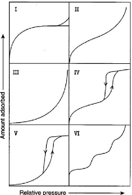
The IUPAC classification of adsorption isotherms is illustrated in Figure 2.4 The six types of isotherm are characteristic of adsorbents that are microporous (type I), nonporous or macroporous (types II, III, and VI) or mesoporous (types IV and V). The differences between types II and III isotherms and between types IV and V isotherms arise from the relative strengths of the fluid-solid and fluid-fluid attractive interactions: types II and IV are associated with stronger fluid-solid interactions and types III and V are associated with weaker fluid-solid interactions. The hysteresis loops usually
exhibited by types IV and V isotherms are associated with capillary condensation in the
Figure 2.4: IUPAC classifications of adsorption isotherms (Barton et al., 1999).
Most of the solid adsorbents of great industrial applications possess a complex porous structure that consists of pores of different sizes and shapes. If the pores are slit shaped measurement used are in term of width but for the pores with a cylindrical shape the term diameter is frequently used.
The significance of pores in the adsorption processes largely depends on their sizes. Because sizes of micropores are comparable to those of adsorbate molecules, all atoms or molecules of the adsorbent can interact with the adsorbate species. That is the
fundamental difference between adsorption in micropores and larger pores like
pore-filling process in which their volume is the main controlling factor (Everett, 1998; Dabrowski, 2001). Thus, as the essential parameter characterizing micropores is their volume usually referred to a unit mass of the solid and characteristics of their sizes. This characteristic is expressed by the micropore distribution function evaluated mainly from the low concentration adsorption data.
In the case of mesopores whose walls are formed by a great number of adsorbent atoms or molecules, the boundary of interphases has a distinct physical meaning. That means that the adsorbent surface area has also a physical meaning. In macropores the action of adsorption forces does not occur throughout their void volume but at a close distance from their walls. Therefore, the monolayer and multilayer adsorption takes place successively on the surface of mesopores, and their final fill proceeds according to the mechanism of capillary adsorbate condensation. Therefore, the basic parameters characterizing mesopores are:
Specific surface area
Pore volume
Pore size or pore volume distribution.
Mesopores, like macropores, play an essential role in the transport of adsorbate
2.2.4 Adsorption Mechanism by Porous Adsorbents
2.2.4.1 Physisorption by Microporous Adsorbents
In the IUPAC classification of pore size, the upper limit of the micropore width was placed at approximately 2 nm. It turns out that this limiting width is somewhat arbitrary since the mechanism of pore filling is not determined by pore width alone.
The high p/p0 plateau of a well-defined Type I isotherm always extends over a wide multilayer range. The great majority of Type I isotherms can be attributed to micropore filling, but there are a few systems like butanol on alumina with which a form of „gas phase autophobicity‟ inhibits the development of the multilayer. This behavior is
not possible with simple adsorptive molecules such as Ar, Kr, N , O and etc. Or even with alkanes and other larger molecules of low polarity. With these adsorptives, the low multilayer slope is a direct consequence of a small external area (Dabrowski, 2001; Sing, 1998).
It is now apparent that Type I isotherms can be broadly divided into two groups. Ultramicroporous carbons and molecular sieve zeolites exhibit high adsorption affinity, their isotherms generally having a high degree of rectangularity with the plateau
approached at very low p/p0. The second group of Type I isotherms are
„supermicroporous‟ activated carbons and oxide xerogels which have wider pores. In
The micropores in activated carbons tend to be slit-shaped. In the
ultramicropores of this shape there is a significant overlap of adsorption forces provided that the pore widths are not much larger than two molecular diameters. This is
manifested in the form of enhanced adsorption energies, which are responsible for the steepness of the isotherm at low p/p0. This process has been termed „primary micropore filling‟. Supermicropores in the range of approximately 2 to 5 molecular diameters are
filled by a combination of surface coverage at low p/p0 and a cooperative process or quasi-multilayer adsorption at higher p/p0 (upto 0.2). Since it involves two overlapping stages, supermicropore filling is not a first order transition, as in the case of capillary condensation (Kruk et al., 1999; Sing, 1998).
2.2.4.2 Physisorption by Mesoporous Adsorbents
The characteristic shape of a Type IV isotherm is the result of surface coverage of the mesopore walls followed by pore filling. The onset of capillary condensation (the pore filling process) is indicated by an upward departure of the isotherm from the multilayer Type II isotherm for the same gas-solid system. The plateau at higher p/p0 is
attained when the mesopore filling is complete (Barton et al., 1999; Sing, 1998).
If the Kelvin equation is used to evaluate the mesopore size, it is necessarily assumed that a simple relationship relates the meniscus curvature to the pore shape and size. Thus, if the pores are cylindrical, the meniscus shape is hemispherical; but if the pores are slit-shaped, the meniscus becomes hemicylindrical. Other assumptions
same density as the liquid adsorptive at the operational temperature (Kruk et al., 1999; Sing, 1998).
A long-standing problem in mesopore analysis is the interpretation of the various
hysteresis loops associated with most Type IV isotherms. For many years it was thought that the desorption branch of the loop represented thermodynamic equilibrium and therefore should be adopted for the pore size analysis. This practice is now questionable since the path of the desorption branch is often dependent on network-percolation effects. On the other hand, it is known that on the adsorption branch delayed
condensation is the result of the persistence of a metastable multilayer, this effect being especially pronounced in slit-shaped pores (Kruk et al., 1999; Sing, 1998; Mercuri et al., 2006).
It is of great advantage to have independent information on the pore shape and connectivity, but the size and shape of the loop itself can also give a useful indication of the predominant pore filling or emptying mechanisms. Thus, a narrow Type H1 loop, with almost vertical and parallel branches, is generally associated with delayed
condensation and very little percolation hold-up, whereas a much broader Type H2 loop (with a very steep desorption branch) has the typical features associated with
network-percolation.
can be obtain, which agrees well with a mean value of approximately 4 nm derived from the volume/ surface ratio (Kruk et al., 1999; Mercuri et al., 2006; Sing, 1998). A
number of other adsorptives such as argon, oxygen, carbon dioxide, sulfur dioxide and various alcohols have been found to give Type H1 hysteresis loops with the 4 nm MCM-41. In another investigation, it was found that the carbon tetrachloride isotherms
determined at temperatures between 273 and 303 K on a 3.4 nm pure silica form of MCM-41 exhibited steep and very narrow hysteresis loops, whereas the corresponding isotherm at 323 K was completely reversible (Beck and Vartuli, 1996; Sing, 1998).
According to Sing, 1998, when they are confined to very narrow ranges of p/p0, the reversible pore-filling steps appear to be equivalent to first order phase
transformations, the p/p0 being dependent on the adsorptive and the temperature. It seems significant that for a given adsorptive the characteristic p/p0 is remarkably close to the lower limit of closure of the hysteresis loop (the limiting chemical potential controlling the stability of the capillary condensate). As a conclusion, the reversible stepwise filling of the mesopores in MCM-41 is due to:
(i) The absence of pore blocking effects. (ii) The tubular pore shape.
(iii) The particular range of its narrow pore size distribution in relation to the
2.2.5 Adsorption Controlling Parameters
Since the discovery of porous materials, the adsorption study between solid and gas has advanced to a new level. There had been numerous studies on adsorption
controlling parameters and can be concluded to the following factors:
(i) Nature of adsorbent and adsorbate. (ii) Surface area of the adsorbent. (iii) Pressure.
(iv) Temperature.
The nature of adsorbent and adsorbate show significant effect on the amount of gas (adsorbate) adsorbed into/ onto adsorbent. Easily liquefy gases such as SO2, NH3,
HCl and CO2 adsorbed more readily than permanent gases like H2, N2 and O2 which do
not liquefy easily. This is the result of Van der Waals or molecular forces of the easily liquefy gases which is much greater than permanent gases. Different type of adsorbents adsorbed different amounts of gas. Vice versa, different type of gases (adsorbate) adsorbed onto adsorbent in a different amounts depends on the nature of the adsorbates such as molecular weight, polarity, molecule size, shape and other physical and
chemical properties (Dabrowski, 2001; Chhatwal and Mehra, 1974).
adsorptivity of adsorbents. Porous materials such as zeolite, mesoporous molecular sieves and carbon molecular sieves can be specifically synthesis with precise pore size distribution and hence can be tailored for a particular separation (Barton et al., 1999; Beck and Vartuli, 1996).
Adsorption capacity also depends on the pressure of the gas in a certain
confinement in the adsorption process. Adsorption of gas basically follow Le Chatelier‟s
principle which stated that with the decrease of pressure, the magnitude of adsorption also decrease and vice versa. Besides that, Le Chatelier‟s principle can also be apply for temperature effects on adsorption. However, the principle is a bit different whereas, the decrease in temperature will result in increase of adsorption magnitude and vice versa. Physical adsorption (physisorption) is very effective particularly at a temperature close to the critical temperature of a given gas. Meanwhile, chemical adsorption
(chemisorption) occurs usually at temperatures much higher than the critical temperature (Dabrowski, 2001; Sing, 1998; Chhatwal and Mehra, 1974).
2.3 Adsorbents
Most solid adsorbents for industrial applications possess a complex porous structure that consists of different sizes and shapes. If the pores are slit shaped, their width is consider as the size. However, for pores with cylindrical shape the term diameter is frequently used.
gas sorption isotherms reflect the relationship between porosity and sorption
(Dabrowski, 2001; Barton et al., 1999). Pores are classified according to pore diameter as follows:
Micropores diameters less than 2 nm;
Mesoporous diameters between 2 and 50 nm;
Macroporous diameters more than 50 nm.
2.3.1 Microporous Materials
In the IUPAC classification of pore size, the upper limit of the micropore width was placed at approximately 2 nm. Any structure below 2 nm in pore size are considered microporous materials such as zeolite A, zeolite Y, ZSM-5, AlPO4-11, AlPO4-5, VPI-5, cloverite and others which mostly are from zeolite type of framework materials. Zeolites occur in nature and have been known for almost 250 years as aluminosilicate minerals. Examples are faujasite, mordenite, offretite, ferrierite, erionite and chabazite. Today, these and other zeolite structures are of great interest in catalysis and other applications, yet their naturally occurring forms are of limited value, because:
i) they almost always contain undesired impurity phases,
ii) their chemical composition varies from one deposit to another and even from one stratum to another in the same deposit,
iii) nature did not optimize their properties for catalytic applications.
conditions, when the zeolite minerals seem to boil because of the fast water loss. The word derives from two Greek words zeo and lithos, which means “stone that boils”. Typically, zeolites are hydrated, porous crystalline aluminosilicates. The framework is an assemblage of SiO4 and AlO4 tetrahedral joined together by sharing oxygen atoms
(Ghobarkar et al., 1999; Weitkamp, 2000).
2.3.1.1 Classification of Zeolites
The term "molecular sieve" is used to describe a class of materials that exhibit selective sorption properties, for instance that are able to separate components of a mixture on the basis of molecular size and shape. The term molecular sieve is used to describe microporous crystalline materials such as aluminosilicates (zeolites), silica molecular sieves, aluminoposphates and related materials.
The extraordinary properties of zeolites are caused by their crystal lattice. Therefore, a proper classification starts from the 3-dimensional bonding of the
tetrahedrally coordinated framework cations. Today about 800 different zeolites are known which can be classified by 119 different zeolite structure types. These structure types are described by a three letter code. Only about l/4 of them are naturally occurring, the others are synthetic. Instead of using the unit cell of the respective zeolite for
The topology of the zeolite framework is given by a unique three-letter code which is not related to the composition of the material. Thus, ZSM-5 and silicalite-1 are materials with MFI topology. Silicalite-1 is a pure silica analogue of ZSM-5 (generally, an MFI type material is regarded as ZSM-5 when there is more than one aluminum per unit cell, for example a SiO2/Al2O3 ratio less than 190) and strictly it cannot be
considered as a zeolite but rather as a silica molecular sieve. The MFI structure is built up by 5-1 secondary building units (SBU; the smallest number of TO4 units, where T is
Si or Al, from which zeolite topology is built) which are link together to form chains as shown in Figure 2.5 and the interconnection of these chains leads to the formation of the channel system in the structure. The MFI structure has a three dimensional pore system consisting of sinusoidal 10-ring channels (5.1 x 5.5 Å) and intersecting straight 10-ring channels (5.3 x 5.6 Å) (Weitkamp, 2000; Han et al., 2005)
2.3.1.2 Structure and Framework of Zeolites
The elementary building units of zeolites are SiO and AlO tetrahedra. Adjacent tetrahedra are linked at their corners via a common oxygen atom, and this result in an
inorganic macromolecule with a structurally distinct three-dimensional framework. It is evident from this building principle that the net formula of the tetrahedra is SiO and AlO2- . The framework of a zeolite contains channels, and channel interintersections
and/or cages with dimensions from 0.2 to 1 nm. Inside these voids are water molecules and small cations which compensate the negative framework charge.
Figure 2.6 shows the structures of four selected zeolites along with their
respective void systems and pore dimensions. In these commonly used representations, the T-atoms are located at the vertices, and the lines connecting them stand for T–O–T bonds. For example, if 24 tetrahedra are linked together as shown in the top line of Figure 2.6, the cubo-octahedron, also referred to as a sodalite unit or β-cage, results. It is an important secondary building unit from which various zeolite structures derive. If sodalite units are connected via their hexagonal faces as shown in Figure 2.6, the structure of the mineral faujasite results. Zeolite Y is of utmost importance in heterogeneous catalysis, for example it is the active component in catalysts for fluid
catalytic cracking. Its pore system is relatively spacious and consists of spherical cages, referred to as supercages, with a diameter of 1.3 nm connected tetrahedrally with four neighboring cages through windows with a diameter of 0.74 nm formed by 12 TO4
-tetrahedra. Zeolite Y is therefore classified to possess a three-dimensional,
Figure 2.6: Structures of four selected zeolites (from top to bottom: faujasite or zeolites X, Y; zeolite ZSM-12; zeolite ZSM-5 or silicalite-1; zeolite Theta-1 or ZSM-22) and their micropore systems and dimensions (Weitkamp, 2000).
2.3.2 Mesoporous Materials
Porous materials have attracted the attention of chemists and materials scientists due to commercial interest in their application in chemical separations and
The discovery of the first ordered (where the pores are ordered periodically), mesoporous molecular sieves has sparked interest throughout the scientific community. These materials, possessing pore sizes in the ~2-50 nm range, have a wide range of potential applications including shape-selective catalysis and sorption of large organic molecules, chromatographic separations, and uses as hosts to confine guest molecules
and atomic arrays. Several reviews on the general classification, properties, synthesis, and potential applications of mesoporous materials have already been studied.
The rational design of structured, complex inorganic frameworks with pores large enough to be used in the various applications awaited a viable synthetic approach. Several years ago, such an approach was discovered, resulting in the synthesis of the first members of an extensive family of silicate/aluminosilicate mesoporous molecular sieves designated as M41S. An unusual mechanism for the formation of these materials, known as liquid crystal templating, in which supramolecular assemblies of cationic alkyhrimethylammonium surfactants serve as components of the template for the formation of these materials, was proposed to account for their formation (Zhao et al., 1996; Mercuri et al., 2006; Barton et al., 1999; Beck and Vartuli, 1996; Kruk et al., 1999).
The discovery of these new materials led to an extension of the structure
directing or templating concepts. That is, traditional zeolite synthesis typically involves the crystallization of a silicate around a single molecule. These new materials extended this single molecule concept making it possible to use a group of molecules like
2.3.2.1 Formation Mechanism of Mesoporous Materials
A new class of mesoporous molecular sieves, M41S, has been discovered by extending the concept of zeolite templating with small organic molecules to longer chain
surfactant molecules. Rather than individual molecular directing agents participating in the ordering of the reagents to form the porous material, assemblies of molecules, dictated by solution energetics, are responsible for the formation of these pore systems. This supramolecular directing concept is illustrated in Figure 2.7 has led to a family of materials whose structure, composition, and pore size can be tailored during synthesis by variation of the reactant stoichiometry, nature of the surfactant molecule, or by postsynthesis functionalization techniques (Zhao et al., 1996; Boger et al., 1997; Barton et al., 1999; Beck and Vartuli, 1996).
Figure 2.7: The formation of microporous molecular sieves using individual small alkyl chain length quaternary directing agents (top) and the formation of mesoporous
The formation mechanism of this mesoporous family of molecular sieves is dictated by two features. The first is the dynamics of surfactant molecules to form molecular assemblies which lead to micelle and, ultimately, liquid crystal formation. The second is the ability of the inorganic oxide to undergo condensation reactions to form extended thermally stable structures. The initial discovery involved the formation
of silicates using alkyltrimethylammonium cationic surfactants in a basic medium. Subsequent efforts have shown these structures can also be formed in acid media and by using neutral normal amines, nonionic surfactants, and dialkyldimethylammonium cationic surfactants. In addition, several mechanistic studies have expanded the initial pathway studies to a more generalized view of an organic/inorganic charge balance driving force for the formation of these structures (Zhao et al., 1996; Zhao et al., 2000; Barton et al., 1999).
Initial speculation on the mechanistic pathway shown in Figure 2.8, leading to the formation of these mesoporous materials considered two possibilities. The first was that the surfactant molecules organize independently of the inorganic silicate
crystallization, and that the siliceous framework polymerizes around these preformed surfactant aggregates. The second was that silicate anions in solution, by virtue of their charge balance with the cationic surfactants, play an intimate role in directing the
formation of the supramolecular surfactant arrays. In either ease a liquid crystal template
Figure 2.8: Possiblemechanistic pathways for the formation of MCM-41: (1) liquid crystal initiated and (2) silicate anion initiated (Beck and Vartuli, 1996).
2.3.2.2 Types of Mesoporous Materials
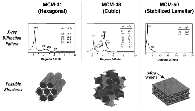
The initial members of the M41S family consisted of MCM-41 (hexagonal phase), MCM-48 (cubic Ia3d phase), and 50 (a stabilized lamellar phase). MCM-41 exhibits an X-ray diffraction pattern containing three or more low angle (below 10° 2θ) peaks that can be indexed to a hexagonal hk0 lattice. The structure is proposed to have an hexagonal stacking of uniform diameter porous tubes whose size can be varied from about 15 to more than 100 Å. An example of the characteristic X-ray diffraction
pattern and proposed structure are shown in Figure 2.9.
MCM-48, the cubic material, exhibits an X-ray diffraction pattern, shown in
Figure 2.9, consisting of several peaks that can be assigned to the Ia3d space group. The structure of MCM-48 has been proposed to be bicontinuous with a simplified
on the concept of an infinite periodic minimal surface of the gyroid form, Q, proposed for water surfactant systems. A proposed structure is also shown in Figure 2.9.
MCM-50, the stabilized lamellar structure, exhibits an X-ray diffraction pattern
consisting of several low angle peaks that can be indexed to h00 reflections. This material could be a pillared layered material with inorganic oxide pillars separating a two dimensional sheet similar to that of layered silicates such as magadiite or kenyaite as illustrated in Figure 2.9. Alternatively, the lamellar phase could be represented by a variation in the stacking of surfactant rods such that the pores of the inorganic oxide product would be arranged in a layered form (Zhao et al., 1996; Beck and Vartuli, 1996; Barton et al., 1999; Choma et al., 2002; Zhao et al., 2000).
Other M41S type mesoporous materials are SBA-1 (cubic Pm3n phase) and SBA-2 (cubic p63/mmc phase). Further materials have been synthesized that are not as readily classified. These materials generally exhibit limited X-ray diffraction
information (one peak) and may contain a random array of pores as shown in
transmission electron micrographs of Figure 2.10. All of these mesoporous materials are characterized by having narrow pore size distributions comparable to microporous materials and extraordinary hydrocarbon sorption capacities which are up to or equal to
Figure 2.9: The X-ray diffraction patterns and proposed structures of 41, MCM-48, and MCM-50 (Barton et al., 1999).
The initial forms of the M41S family were synthesized as silicates and aluminosilicates. Subsequent synthesis efforts have produced materials having heteroatom substitution as well as nonsiliceous products. The initial nonsiliceous materials included oxides of W, Fe, Pb, Mo and Sb. Many of these materials exhibited very poor thermal stability and upon the removal of the template, the structures
collapsed. Mesoporous zirconia and titania materials have been prepared but only exhibit satisfactory thermal stability and thus are believed to be composed of extended and complete oxide nets of the elements (Zhao et al., 1996; Barton et al., 1999; Zhao et al., 2000).
2.3.2.3 Application of Mesoporous Materials
Potential applications of these mesoporous molecular sieves are as exciting as their discovery. In earlier years, mesoporous materials were examined for applications relating to their large pore volumes. Such applications including the use of mesoporous adsorbents for removal of volatile organic compound (VOC) in the industrial setting. In pursuit of such goals, the behavior of a variety of adsorbates has now been
comprehensive. Almost all reported data agree that mesoporous materials have large accessible internal pore volumes which can be filled at pressures appropriate with the pore size (Zhao et al., 2001; Beck and Vartuli, 1996).
The sorptive properties of MCM-41, the hexagonal member of the M41S family of mesoporous silicates, have been extensively characterized using a variety of
composition, pore size, and nature of the adsorbent. Current study of adsorption isotherms on gases like argon, nitrogen and oxygen using well characterized MCM-41 sample confirm that MCM-41 has a narrow pore size distribution and exhibits
extraordinary pore volume compared to classical microporous materials (Zhao et al., 1996; Dabrowski, 2001; Barton et al., 1999; Beck and Vartuli, 1996).
Despite the impressive adsorption capacities of these materials, their type IV isotherm behavior requires the adsorbate, in the gas phase, to be at high partial pressure. However, by contrast in most industrial application, for example VOC uptake, where adsorption at low partial pressures (type I isotherms) is required and poses constraint to the mesoporous materials application. Industrial applications which utilize mesoporous materials are catalytic processes, mini-reactors for electron transfer reaction, as a host for quantum confinement, molecular wires and shape-selective polymerization (Beck and Vartuli, 1996).
2.3.3 Modification of Porous Materials