Transactions of the 17th International Conference on Structural Mechanics in Reactor Technology (SMiRT 17)
Prague, Czech Republic, August 17 –22, 2003
Paper # C02-2
Calculational Analysis of WWER-1000 Fuel Assembly Operational
Deformation
V.L.Danilov1), S.V.Zarubin1), V.P.Semishkin 2), N.V.Shary2)
1) Moscow State Technical University named after N.E.Bauman, Moscow, Russia 2) FSUE Design and Experimental Organization “Gidropress”, Podolsk, Russia
ABSTRACT
The mathematical model of WWER-1000 fuel assembly (FA) deformation is described considering the specific features and conditions of operational loading under radiation effects typical for the reactor core. The main attention is paid to description of mechanical interaction of fuel rods with spacer grids (SG). The spacer grids are considered in the form of cellular deformable structures permitting fuel rod slippage inside itself. The cases of interaction of fuel assemblies between themselves and of their group deforming within the volume of the whole core on the basis of simplified FA deformation model supplemented with the block of determination of contact forces are considered.
KEY WORDS: nuclear reactor, core, fuel assembly, spacer grid, fuel rod, slippage, transverse-longitudinal bending,
inter-assembly gaps.
INTRODUCTION
The given paper deals with the main principles of construction of mathematical model of WWER-1000 core deformation. The fuel assembly is represented in the form of bar structure with detalization of contact interaction of fuel rods with spacer grid cells. The basis of the calculation procedure is a thermo-mechanical model of behaviour of fuel rods and guiding channels (GC) fastened with SG over the FA height.
Numerical study on the basis of rather detailed finite element model of FA showed that for the most actual situations some simplified hypotheses can be assumed. Actually, due to a large number of fuel rods they can be considered as separate fibres of the bar working in tension and compression (as it is usually done in the simplest theory of bar bending, ref. [1]). But it should be taken into account that there is a possibility of self-motion of these fibres in longitudinal direction for simulation of slippage of fuel rods in the SG cells. For the spacer grids themselves an assumption can be made that they remain plane in the course of FA deforming and permit only longitudinal motion of FA bar elements. All finite-difference relationships and equations for calculation of stressed-strained state of FA elements are made on the basis of the hypothesis of plane sections for non-uniform bar representing a simplified model of FA structure. Distortion and turning of FA cross-section, with presence of slippage of bar elements in SG cells, is reflected by introducing the “dummy” strains.
Application of the above-mentioned simplifying assumptions allows actually to construct a model of FA deformation on the basis of traditional theory of transverse-longitudinal bending of the bar. The given simplified model reduces greatly the time for obtaining the numerical solution (especially it concerns the computation time) in comparison with the complete mathematical model of FA deformation. Nevertheless, within the framework of this simplified approach the strain effects of irradiation and elevated temperatures on structural materials are considered easily.
FA DEFORMATION MODEL
The FA deformation model, presented in the given paper, is a development of calculational procedure of ref. [2]. In considering the deforming of the main FA bar elements it was believed that total strain ε(j) in j-element of the bar is
written down as
( ) ( ) ( ) ( ) ( ) ( )fj t
j j c
j e
j
j =ε +ε +ε +ε +ε
ε φ . (1)
Superscripts mean: “e”- elastic strain
( ) ( )j ( )j e
j =σ E
ε , (2)
Having combined the summands not related to elastic strain the expression (1) can be rewritten in the following form
( ) ( ) ( )nj e
j
j =ε +ε
ε . (3)
Having considered the FA section between two SGs. Let’s designate: z – longitudinal FA axis coinciding with central tube; x and y – two mutually perpendicular symmetry axes of hexagonal cross-section of WWER-1000 FA. Coordinates of i- and i+1-SG we designate as z(i) and z(i+1), coordinate of the middle of the considered section is z(i+1/2), length of section ∆z(i+1/2).
For each considered section a vector of strain parameters can be introduced
T
0, ,
∆ ϕ ∆ − ∆ ϕ ∆ − ε = z z y x
È . (4)
where ε0 – mean strain of the section, ∆ϕx и ∆ϕy – difference in turning angles of i- and i+1-SG relative to axes x and y ,
respectively.
Turning angles of normals to FA axis in the form of generalized bar and SG turning angles should be differentiated. If the SG compliance, taking into account a possibility of “skewness” of the grid under action of transverse forces, then for SG deviation from the normal to the axis of generalized bar the following can written down
(xory) kS
(
Q(yorx) N GS(xory))
GS = − ϕ
ϕ
∆ , (5)
where index “SG” means that turning angle of the SG is considered and not of the normal; kS – compliance considering
distortion of a bundle of fuel rods and GC on the section between two adjacent SGs and the total turning of fuel rod bundle in SG cells, Q – transverse force, N – normal force, ∆ϕДР – angle of SG “skewness”. The turning angles of the normal (ϕx and ϕy) and displacements (u and v) sections, limiting the considered section “i+1/2” of FA, are bound with
the relationships ( ) ( ) ( ) ( ) ( ) ( )
(
( ) ( ))
( ) ( )(
( ) ( ))
. 2 1 , 2 1 , , 1 2 1 1 1 2 1 1 1 GS GS 2 1 1 1 GS GS 2 1 1 + + + + + + + + + + + + ϕ + ϕ ∆ + = ϕ + ϕ ∆ + = ϕ ∆ − ϕ ∆ + ϕ ∆ + ϕ = ϕ ϕ ∆ − ϕ ∆ + ϕ ∆ + ϕ = ϕ i x i x i i i i y i y i i i i y i y i y i y i y i x i x i x i x i x z v v z u u (6)Using equations for resultant internal forces in cross-section of the considered section, a matrix equation for the vector of strain parameters can be easily formed
[ ]
C FÈ = −1 , (7)
where vector F is of the following form (A(j) – area of j-element of the bar)
( ) ( ) ( ) ( ) ( ) ( ) ( ) ( ) ( ) ( ) ( ) ε + − ε + − ε + =
∑
∑
∑
j j j j n j y j j j j n j x j j j n j x A E M y A E M A E N F .Matrix of stiffness coefficients [C] is written down as the following
[ ]
( ) ( ) ( ) ( ) ( ) ( ) ( ) ( ) ( ) ( ) ( ) ( ) ( ) ( ) ( ) ( ) ( ) ( ) ( ) ( ) ( ) ( ) ( ) ( ) ( ) ( ) ( ) ( ) =∑
∑
∑
∑
∑
∑
∑
∑
∑
j j j j j j j j j j j j j j j j j j j j j j j j j j j j j j j j j j j j j x A E y x A E x A E y x A E y A E y A E x A E y A E A E 2 2 C .forces
( )
( )(
( ))
( )
∑
( )(
( ))
∑
= =
− +
+ =
− +
+ =
i
k
k k y
y
i
k
k k x
x
u u q z M u N M
v v q z M v N M
1 0 0
1 0 0
, ,
(8)
where Mx0(z) and My0(z) – moments from external transverse loads (including reactions in supports); N0 – total force of
spring unit compression, q(k) – longitudinal forces reduced to k-SG.
On the basis of the above-mentioned relationship and method of initial parameters, formulated for calculation of straight bars under bending, ref. [1], a procedure of determination of stressed-strained state of FA components is constructed with the components of strains εn known beforehand. With presence of considerable creep for consideration
of nonelastic strains the evident stepwise procedure is used with automatic choosing of step in time.
Consideration of slippage of bar elements in SG cells requires construction of iteration procedure because in slippage the redistribution of internal forces (stresses) occurs in FA bar elements. Consideration of slippage of bar elements of FA in SG units is made with the use of dummy strains. Iteration procedure is actually a stepwise procedure of calculation similar to the evident stepwise method with presence of considerable creep. The main difference of the slippage consideration procedure from the algorithm of calculation in creep is that the nonelastic straining takes place only due to special “dummy” viscous elements placed into SG cells. Strain of these elements is recalculated into “dummy’ strains εf in expression (1). Besides, the iteration procedure is performed with the “frozen” time at the end of
time step of the calculation algorithm in creep. It is clear that slippage of j-element of the bar in the cell of SG located between i- and i+1 sections is possible with meeting the following condition before the beginning of the iteration procedure
( ) ( ) ( )j ( )( )ij i
j i
j −σ A ≤∆
σ
− +
2 1 2 1
, (9)
where ∆( )( )ij - friction force in SG cell (each cell can have
its own value of friction force). Increments of dummy strains on each iteration when calculating one cell of SG shall meet the following relationship
( ) ( ) 2 0
1 2 1 2
1 2 1
= ∆ ε ∆ + ∆ ε
∆
− − +
+ f i i
j i
i f
j z z . (10)
In numerical calculation of FA the “ random” assigning of friction forces in SG cells is made (both for fuel rods, and for guiding channels) in definite intervals with the help of a gauge of “pseudorandom” numbers. The approach in “random” assigning the friction forces in SG cells allows to describe the spontaneous distortion of the assembly under longitudinal loading even with absence of the initial curvature.
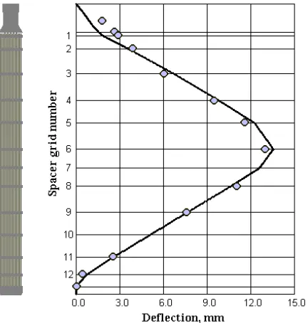
Fig. 1 presents a comparison of calculated results and experimental data for transverse bending of FA mockup under action of horizontal (transverse) load.
MODEL OF CONTACT INTERACTION OF FA ENSEMBLE
As shown by NPP operation experience, in the course of life under action of mechanical loads, heat fields and radiation exposure the distortion of fuel assemblies occurs with the subsequent overlapping of gaps between them and occurrence of the forces of contact interaction which, in their turn, make a considerable effect on the character of deformation of the contacting FAs. Thus, for adequate description of FA behaviour in the core a contact problem shall be solved at each time step, alongside with the analysis of stressed-strained state of each FA under action of the assigned influencing factors. Information on distribution of contact forces in the core is, in its turn, an input information for determination of stressed-strained state of each assembly.
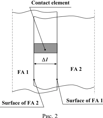
For the analysis of FA contact interaction the special contact elements are introduced into consideration (Fig. 2) following the mutual arrangement of surfaces of possible contact, ref. [3]. Let’s provide the each element with viscoelastic properties. Then the total strain of the element will be determined as a sum of elastic and viscous component
Fig. 1. Line of FA mockup deflection in bending under action of transverse force; solid line – calculation,
v e+ε
ε =
ε . (11)
On the other hand, the complete deformation of the element is determined as
l l
∆ − =
ε , (12)
where l – initial length of the contact element, and ∆l – overlapping of the contacting surfaces with the accuracy to a sign equal to full elongation of element. According to Hooke’s law for elastic strain the following can be written down
D F e =−
ε (13)
whеre F – contact force, D – tension-compression stiffness of the element cross-section. The law of the element viscous straining we assign in the form of
l l B v
∆ =
ξ (14)
whеre B = const. Finally, for k-step of the iteration process for specifying the contact forces the equation (11) will be of the following form
k ev k
k F C l
F = −1+ ∆ (15)
The given iteration cycle is the intrastep cycle relative to the step of the main time of FA deformation process. That is, in the course of counting. The same way as in consideration of slippage in FA straining model, the “freezing” of the main time if made after each step for performance of the iteration cycle on specifying the values of contact forces. The order of stiffness parameter of contact element, Cev, can be evaluated from the solution of reverse contact problem
within the elasticity, or by numerical experiment.
As seen from the obtained formula, with presence of overlapping the value of contact force increases, in occurrence of a gap the drop in the force value takes place. Numerical experiment shows that determination of contact forces with the use of constant value of stiffness parameters in the course of counting could result either in disagreement of numerical solution due to jumpwise change in contact forces, or to unjustified delaying in agreement. To avoid the mentioned phenomena a procedure of correction of the contact element stiffness parameter is provided at the stage of the agreement analysis. With jumpwise change in contact forces the decrease in stiffness Cev is made. Increase in
stiffness characteristic is made in case of delay in agreement of numerical solution with presence of a tendency to agreement.
NUMERICAL RESULTS
The considered simplified model of deformation of separate FA and the model of contact interaction of FA ensemble formed the basis of computer code intended for calculation of behaviour of FA ensemble in the reactor core. Fig. 3 represents the results of calculation of one of versions of FA ensemble deformation in the rector core. As an example of the calculation, the deformation and interaction of 163 fuel assemblies constituting the core of WWER-1000, are considered. The given numerical simulation allows to follow the variation in inter-assembly gaps, contact forces and deflection of separate FAs during t he time interval considered. The figure represents displacements of each FA (with arrows) and the contact forces between interacting FAs (sections connecting centers of contacting FAs) at the level of central SG for one of the time moments.
Contact element
Surface of FA 2 Surface of FA 1
FA 1 FA 2
∆l
Fig. 3. Calculated displacements and contact forces of FA in WWER-1000 reactor core at central SG level
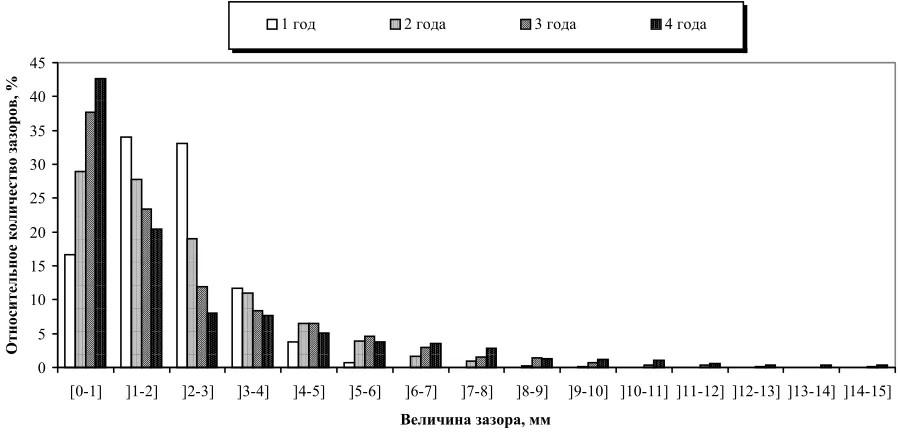
One of the main tasks of thermomechanical calculation of the core is a prediction of distribution of inter-assembly gaps and their change in the course of fuel burnup because namely they influence the neutron physics and thermohydraulic characteristics of the core. Fig.4 represents the calculated histogram of distributions of inter-assembly gaps for different time moments. It should be noted that the presented results on distribution of inter-assembly gaps do not contradict the experimental data.
0 5 10 15 20 25 30 35 40 45
[0-1] ]1-2] ]2-3] ]3-4] ]4-5] ]5-6] ]6-7] ]7-8] ]8-9] ]9-10] ]10-11] ]11-12] ]12-13] ]13-14] ]14-15]
Величина зазора, мм
Относительное количество зазоров, %
1 год 2 года 3 года 4 года
CONCLUSION
The mathematical model of thermomechnical behaviour of FA allows to consider:
• Spatial joint deformation of fuel rod bundle, guiding channels and spacer grids.
• Initial drawbacks in FA design, initial internal forces occurring in fuel rods and SG during assembling of FA into the common structure.
• Non-uniform temperature fields..
• Heat and radiation effects in FA components under neutron irradiation.
• SG stiffness characteristics.
• Structural peculiarities of FA design version.
• Change in FA properties in the course of operation.
• Outside effects on FA in the form of forces from the spring unit and hydrodynamic forces from the effect of coolant flow.
• Contact interaction with adjacent FAs.
Numerical simulation of FA ensemble deformation with the use of the developed computer code allows to analyze possible design solutions to provide for geometrical stability of FA and to keep the design thermohydraulic and neutron physics characteristics in the course of the whole service life.
REFERENCES
1. Birger, I.A. Bars, plates, shells – M. Fizmatlit, 1992.
2. Danilov V.L., Zarubin S.V., Semishkin V.P., Shary N.V. “Calculation and theoretical analysis of
stressed-strained state of fuel assembly of WWER-1000”, Proc. of report of the 2nd All-Russian Scientific and Technical
Conference “Safety Assurance of NPP with WWER”, Vol. 3, pp. 292-296, Podolsk, Russia, November 2001. 3. Danilov V.L., Dobrov M.V., Zarubin S.V. “Analysis of leak-tightness of metal-plastic tubes joint.” Materials of