CCIS System Manual
®
MAY, 2000
functions, or features, at any time, without notice.
NEC America, Inc. has prepared this document for use by its employees and customers. The information contained herein is the property of NEC America, Inc. and shall not be reproduced without prior written approval from NEC America, Inc.
NEAX and Dterm are registered trademarks of NEC Corporation. MATWorX is a trademark of NEC Corporation.
Copyright 2000
NEC America, Inc.
ISSUE 1 ISSUE 2 ISSUE 3 ISSUE 4
DATE MAY, 2000 DATE DATE DATE
ISSUE 5 ISSUE 6 ISSUE 7 ISSUE 8
DATE DATE DATE DATE
ISSUE 1 ISSUE 2 ISSUE 3 ISSUE 4
DATE MAY, 2000 DATE DATE DATE
ISSUE 5 ISSUE 6 ISSUE 7 ISSUE 8
DATE DATE DATE DATE
ISSUE 1 ISSUE 2 ISSUE 3 ISSUE 4
DATE MAY, 2000 DATE DATE DATE
ISSUE 5 ISSUE 6 ISSUE 7 ISSUE 8
DATE DATE DATE DATE
2 299 1
300 1
301 1
302 1
303 1
304 1
305 1 306 1
307 1
308 1 309 1
310 1
311 1 312 1
313 1
314 1 315 1
316 1
TABLE OF CONTENTS
Page
LIST OF FIGURES . . .
v
LIST OF TABLES . . . vi
INTRODUCTION. . .
1
PURPOSE . . . . . 1
OUTLINE OF THIS MANUAL . . . 1
TERMS IN THIS MANUAL . . . 2
REFERENCE MANUAL. . . 2
CHAPTER 1
GENERAL INFORMATION . . .
3
SYSTEM OUTLINE . . . 4
DTI . . . . . . 5
CCH . . . . . . . 5
PLO . . . . . . . 6
No. 7 CCIS . . . 7
Digital Network . . . 7
Analog Network . . . 8
Centralized Billing . . . . 9
Inter-Office Digital Data Transmission through No. 7 CCIS . . . 12
CARD NAME AND FUNCTION . . . 13
SYSTEM CAPACITY . . . 16
No. 7 CCIS with Digital Interface . . . 16
No. 7 CCIS with Analog Interface . . . 16
TIME SLOT ASSIGNMENT CONDITION . . . 17
Time Slot Allocation for DTI Card . . . 18
Number of Time Slots Required for DTI/CCH Card . . . 19
DTI SPECIFICATIONS . . . 24
Transmission Characteristics . . . 24
Frame Configuration of 24-DTI . . . 25
Frame Configuration of 30-DTI . . . 30
MODEM Specifications . . . 31
SERVICE FEATURES. . . 32
NETWORK STRUCTURE CONSIDERATIONS . . . 35
Determining System Configuration . . . 35
CHAPTER 2
INSTALLATION . . . 53
PRECAUTIONS. . . 54
Static Electricity Guard . . . 54
REQUIRED EQUIPMENT . . . 57
INSTALLATION PROCEDURE . . . 59
No. 7 CCIS with Digital Interface . . . 59
Mounting DTI Card . . . 60
Mounting CCH Card . . . 61
Mounting EXPMEM Card . . . 62
Mounting AP00 Card . . . 63
Mounting CONN Card . . . 64
Mounting M10 Card . . . . 65
Selection of PLO in MP Card . . . 66
Cable Connection via MDF . . . 67
Cable Connection via CONN Card . . . 70
Optical Cable Connection . . . 72
No. 7 CCIS with Analog Interface . . . 75
Mounting LDT/ODT Card . . . 76
Cable Connection at CCH and MODEM . . . 77
CHAPTER 3
SYSTEM DATA PROGRAMMING . . . 81
HOW TO READ THIS CHAPTER . . . 82
NO. 7 CCIS WITH DIGITAL INTERFACE . . . 83
DTI Assignment . . . 84
CCH Assignment . . . 89
Numbering Plan Assignment . . . 91
Inter-Tenant Connection Assignment . . . 95
Example of No. 7 CCIS with Digital Interface . . . 98
NO. 7 CCIS WITH ANALOG INTERFACE . . . 108
LDT/ODT Assignment . . . 109
CCH Assignment . . . 114
Numbering Plan Assignment . . . 114
Inter-Tenant Connection Assignment . . . 114
NO. 7 CCIS FEATURE PROGRAMMING . . . 115
ATTENDANT CAMP-ON WITH TONE INDICATION-CCIS . . . 116
BROKERAGE-HOT LINE-CCIS . . . 118
BUSY VERIFICATION-CCIS . . . 120
CALL BACK-CCIS . . . 122
CALL FORWARDING-ALL CALLS-CCIS . . . 125
CALL FORWARDING-BUSY LINE-CCIS . . . 130
CALL FORWARDING-DON’T ANSWER-CCIS . . . 135
CALL TRANSFER-ATTENDANT-CCIS. . . 147
CALLING NAME DISPLAY-CCIS . . . 149
CALLING NUMBER DISPLAY-CCIS. . . 151
CENTRALIZED BILLING-CCIS . . . 154
AP Initialization . . . 155
SMDR with AP00 Programming (1) . . . 158
Programming for Center Office . . . 158
Built-in SMDR Programming . . . 162
SMDR with AP00 Programming (2) . . . 164
CENTRALIZED DAY/NIGHT MODE CHANGE-CCIS . . . 179
CENTRALIZED MAT-CCIS (FUTURE ENHANCEMENT). . . 181
CONSULTATION HOLD-ALL CALLS-CCIS . . . 185
DATA LINE SECURITY-CCIS . . . 187
DELUXE TRAVELING CLASS MARK-CCIS . . . 188
DIAL ACCESS TO ATTENDANT-CCIS. . . 192
DIRECT-IN TERMINATION-CCIS . . . 194
DISTINCTIVE RINGING-CCIS . . . 198
DO NOT DISTURB-CCIS . . . 199
DUAL HOLD-CCIS . . . 202
FLEXIBLE NUMBERING OF STATIONS-CCIS . . . 203
HOT LINE-CCIS . . . 205
HOUSE PHONE-CCIS . . . 207
INCOMING CALL IDENTIFICATION-CCIS . . . 209
LDN NIGHT CONNECTION-CCIS . . . 211
LINK ALARM DISPLAY-CCIS . . . 215
MESSAGE WAITING LAMP SETTING-ATTENDANT-CCIS. . . 216
MESSAGE WAITING LAMP SETTING-STATION-CCIS. . . 217
MISCELLANEOUS TRUNK ACCESS-CCIS . . . 218
MISCELLANEOUS TRUNK RESTRICTION-CCIS . . . 219
NIGHT CONNECTION-FIXED-CCIS. . . 220
NIGHT CONNECTION-FLEXIBLE-CCIS. . . 221
OUTGOING TRUNK QUEUING-CCIS . . . 225
PAGING ACCESS-CCIS . . . 227
RESTRICTION FROM OUTGOING CALLS-CCIS . . . 229
SINGLE-DIGIT STATION CALLING-CCIS . . . 230
STATION-TO-STATION CALLING-CCIS . . . 232
TOLL RESTRICTION-3/6 DIGITS-CCIS . . . 233
CHAPTER 4
CIRCUIT CARD INFORMATION . . . 259
HOW TO READ THIS CHAPTER . . . 260
MOUNTING LOCATION OF CIRCUIT CARD . . . 261
Circuit Card Mounting Slots . . . 261
LIST OF REQUIRED CARDS . . . 262
PN-CP14 (MP) . . . 263
PN-CP15 (FP). . . 268
PN-AP00-B (AP00) . . . 270
PN-24DTA-C (DTI) . . . 276
PN-30DTC-A (DTI) . . . 282
PN-SC00 (CCH) . . . 288
PZ-M537 (EXPMEM) . . . 291
PZ-M542 (CONN) . . . 294
PZ-M557 (CONN) . . . 296
PN-2LDTA (LDT) . . . 298
PN-M10 (M10) . . . 299
PN-2ODTA (ODT). . . 301
PN-2ODTB (ODT). . . 302
CHAPTER 5
OPERATION TEST . . . 303
LOOP-BACK TEST . . . 304
INTEROFFICE TRANSMISSION LINE TEST . . . 310
PLO OPERATION TEST . . . 313
Clock Signal Generation Test . . . 313
Clock Signal Synchronization Test . . . 314
Interoffice Synchronization Test . . . 316
Figure 1-1 No. 7 CCIS System Outline . . . 4
Figure 1-2 Clock Supply Route . . . 6
Figure 1-3 No. 7 CCIS with DTI . . . 7
Figure 1-4 No. 7 CCIS with LDT/ODT . . . 8
Figure 1-5 Centralized Billing . . . 9
Figure 1-6 Accommodation of DTI/CCH into TDSW . . . 17
Figure 1-7 Time Slot Allocation for DTI . . . 18
Figure 1-8 CCH Time Slot Assignment (for No. 7 CCIS with Digital Interface) . . . 20
Figure 1-9 CCH Time Slot Assignment (for No. 7 CCIS with Analog Interface) . . . 21
Figure 1-10 Frame Configuration of 24-DTI (12-Multi Frame) . . . 25
Figure 1-11 Frame Configuration of 24-DTI (24-Multi Frame) . . . 27
Figure 1-12 Frame Configuration of 30-DTI . . . 30
Figure 1-13 Network Structuring . . . 35
Figure 1-14 Example of Station Number (Closed Numbering) . . . 42
Figure 1-15 Example of Office Code and Station Number (Open Numbering) . . . 42
Figure 2-1 Static Electricity Guard . . . 54
Figure 2-2 Static Electricity Guard . . . 55
Figure 2-3 Installation Procedure for No. 7 CCIS with Digital Interface . . . 59
Figure 2-4 DTI Cable Connection via MDF . . . 67
Figure 2-5 Location of the AP Slots and the LTC Connectors for DTI . . . 68
Figure 2-6 Example of Cable Connection via MDF . . . 69
Figure 2-7 DTI Cable Connection via CONN Card . . . 70
Figure 2-8 Example of Cable Connection via the CONN Card . . . 71
Figure 2-9 Outline of Optical Cable Connection . . . 72
Figure 2-10 Example of MDF Cross Connection for M10 Card (1 of 2) . . . 73
Figure 2-10 Example of MDF Cross Connection for M10 Card (2 of 2) . . . 74
Figure 2-11 Installation Procedure for No. 7 CCIS with Analog Interface . . . 75
Figure 2-12 Cabling of RS NORM-4 CA-A/RS NORM-4S CA-A (for Common Signaling Data Link via MODEM) . . . 77
Figure 2-13 Cabling of LINE Cable (for Common Signaling Data Link via MODEM) . . . 77
Figure 2-14 Cabling of RS NORM-4 CA-A/RS NORM-4S CA-A (for Common Signalling Data Link via LDT/ODT) . . . 78
Figure 2-15 Location of the AP Slots and the LTC Connectors for CCH . . . 79
Figure 2-16 Cabling of LINE Cable (for Common Signalling Data Link via LDT/ODT) . . . 80
Figure 3-1 Programming Procedure (for No. 7 CCIS with Digital Interface) . . . 83
Figure 3-2 Programming Procedure (for No. 7 CCIS with Analog Interface) . . . 108
Figure 4-1 Mounting Location . . . 261
Figure 5-1 Loop-Back Test . . . 304
Table 1-1 Card Name and Function . . . 13
Table 1-2 System Capacity for No. 7 CCIS with Digital Interface . . . 16
Table 1-3 System Capacity for No. 7 CCIS with Analog Interface . . . 16
Table 1-4 Number of Time Slots Required per DTI/CCH/AP00 Card (for No. 7 CCIS with Digital Interface) . . . 22
Table 1-5 Number of Time Slots Required per CCH/AP00 Card (for No. 7 CCIS with Analog Interface) . . . 23
Table 1-6 Transmission Characteristics . . . 24
Table 1-7 12-Multi Frame Bit Assignment . . . 26
Table 1-8 24-Multi Frame Bit Assignment . . . 28
Table 1-9 Time Slot Assignment of 30-DTI . . . 31
Table 1-10 List of No. 7 CCIS Service Features . . . 32
Table 2-1 Required Equipment for No. 7 CCIS with Digital Interface . . . 57
Table 2-2 Required Equipment and Cable for No. 7 CCIS with Analog Interface . . . 58
Table 4-1 List of Required Cards . . . 262
Table 5-1 Alarm Indications on the 24DTI Card (Loop-Back Test) . . . 307
Table 5-2 Alarm Indications on the 30DTI Card (Loop-Back Test) . . . 308
Table 5-3 Alarm Indications on 24DTI (Interoffice Transmission Line Test) . . . 311
INTRODUCTION
PURPOSE
This manual explains the installation and programming procedure for providing No. 7 Common
Channel Inter-Office Signaling (No. 7 CCIS) system to the NEAX2000 IVS
2/NEAX7400 ICS
M100MX/NEAX2000 INTEGRATED VOICE SERVER.
OUTLINE OF THIS MANUAL
This manual consists of five chapters. The contents of CHAPTER 1 through 5 are outlined below.
CHAPTER 1
GENERAL INFORMATION
This chapter explains the system outline, the name and functions of circuit cards required,
system capacity, time slot assignment condition, system specifications, available service features
with No. 7 CCIS, and network structure conditions for CCIS system.
CHAPTER 2
INSTALLATION
This chapter explains the required equipment and installation procedure.
CHAPTER 3
SYSTEM DATA PROGRAMMING
This chapter explains the programming procedure for providing CCIS system, and also explains
the general description, programming procedure, operating procedure, and hardware
requirement of each service feature.
CHAPTER 4
CIRCUIT CARD INFORMATION
This chapter explains the mounting location, the meaning of lamp indications, and the method of
switch settings of each circuit card for the No. 7 CCIS system.
CHAPTER 5
OPERATION TEST
TERMS IN THIS MANUAL
Usually, PBX system is designated as “PBX” or “system”.
When we must distinguish between the PBX systems, they are designated as follows.
IVS: NEAX2000 IVS
2/NEAX7400 ICS M100MX/NEAX2000 INTEGRATED VOICE SERVER
IMX: NEAX2400 IMS (IMX)/NEAX7400 ICS M140MX or more/NEAX7400 IMX M240 or more
REFERENCE MANUAL
During installation, refer also to the manuals below:
Command
Manual
Describes Customer Administration Terminal (CAT)
operation, command function and setting data required for
programming the system, and Resident System Program.
Office Data Programming Manual
Contains the Customer Specification Sheet and Office Data
Programming Sheet.
MATWorX
Studio
User’s
Guide
Describes the Maintenance Administration Terminal
(MATWorX Studio) program operation.
Maintenance
Manual
Describes maintenance service features and the
recommended trouble shooting procedure.
GENERAL INFORMATION
SYSTEM OUTLINE
The PBX can be interfaced with a Public Network or Tie Line Network by No. 7 CCIS Signaling.
For adding No. 7 CCIS to the system, it is necessary to install the 24/30 channel Digital Trunk
Interface (DTI) for a digital network or LDT (Loop Dial Trunk)/ODT (2 wire E&M or 4 wire E&M
Trunk) for an analog network via a MODEM, and a Phase Locked Oscillator (PLO) for network
synchronization. Also, it is necessary to install a Common Channel Handler (CCH).
The CCH receives/transmits common signaling data from/to the distant office. In each local
office, the PBX can provide Centralized Billing function in addition to a variety of inter-office
service features.
NOTE: Centralized Day/Night Mode Change, Centralized MAT and Number Portability feature
require CCIS No. 7 networking with the IMX.
For addition of the Centralized Billing function, an Application Processor (AP) or Built-in SMDR
of MP card (for Local Office only) is required.
Figure 1-1
shows the system outline of No. 7 CCIS
for the PBX.
Figure 1-1 No. 7 CCIS System Outline
PBX
24/30 CH 24/30 CHANNEL PCM DIGITAL LINE
CLOCK SIGNAL DTI
MP (PLO)
MP (PLO) DIGITAL
PBX
CCH
AP
DTI
DTI : 24/30 Channel Digital Trunk Interface CCH: Common Channel Handler
PLO : Phase Locked Oscillator
DTI
The Digital Trunk Interface (DTI) interfaces the PBX directly to a 24/30 channel PCM
transmission line. The DTI has the following functions.
For 24-DTI:
• Unipolar/Bipolar Conversion (AMI Format/B8ZS Format)
• Signaling Insertion/Extraction
• Alarm Detection/Insertion
• Digital PAD on Voice Signal Transmission
• Loop-Back Test (Local/Remote Loop Back)
• Cyclic Redundancy Checking (based on ITU-T Rec. G704)
For 30-DTI:
• Unipolar/Bipolar Conversion (HDB3 Format)
• Signaling Insertion/Extraction
• Alarm Detection/Insertion
• Digital PAD on Voice Signal Transmission
• Cyclic Redundancy Checking (based on ITU-T Rec. G704)
• Channel Associated Signaling (based on ITU-T Rec. 0421 Digital R2 Signaling Code)
For connection of a 24-DTI and transmission line, twisted-pair cables are used, and for
connection of a 30-DTI and transmission line, twisted-pair cables or coaxial cables are used.
CCH
PLO
The Phase Locked Oscillator (PLO) is responsible for providing synchronization between the
TDSW and another office. In this system, the internal PLO equipped with the MP card is used.
The PLO generates a synchronized clock signal according to the source clock signals supplied
from the source office within the network, and supplies the generated clock signal to the TDSW.
The PLO is supplied with clock signals extracted from the DTI. The PLO can be equipped with
two clock supply routes; one is the route from the source office, and the other is a standby route
from a sub-source office. When no clock signals from the source and the sub-source office arrive
due to a transmission line failure, the PLO keeps generating the clock signals in phase with the
previous source clock.
Figure 1-2
shows an example of clock supply route configuration.
Figure 1-2 Clock Supply Route
PLO TDSW
SOURCE OFFICE
~
SOURCECLOCK
RECEIVER/LOCAL-RECEIVER OFFICE
PBX
DTI
DTI TDSW RECEIVER OFFICE
DTI
DTI
DTI TDSW SUB-SOURCE OFFICE
PLO DTI
DTI DTI
TDSW
DTI
DTI
PLO
No. 7 CCIS
The PBX can provide No. 7 CCIS via either a digital network or an analog network. Regardless
of the relevant network being a digital network or an analog network, CCH (Common Channel
Handler) to control the common signaling channel is required.
DIGITAL NETWORK
When No. 7 CCIS is provided via a digital network, the CCH is connected to the DTI by a fixed
path in the TDSW and transmits/receives common signaling data to/from the distant office
through a predetermined channel. Voice signals are transmitted/received on each line basis
through other channels.
Figure 1-3
shows the system configuration of No. 7 CCIS provided via a digital network.
Figure 1-3 No. 7 CCIS with DTI
TDSW DIGITAL PBX
DTI 24/30 CHANNEL PCM DIGITAL LINE DTI
CCH
TDSW PBX
DTI : 24/30 Channel Digital Trunk Interface CCH : Common Channel Handler
PLO : Phase Locked Oscillator MP
(PLO)
ANALOG NETWORK
When No. 7 CCIS is provided via an analog network, the CCH is connected to the Common
Signaling Channel Controller in the distant office via MODEMs, directly. Voice signals are
transmitted/received through analog trunks (LDT/ODT).
Figure 1-4
shows the system configuration of No. 7 CCIS provided via analog network.
Figure 1-4 No. 7 CCIS with LDT/ODT
MP TDSW DIGITAL PBX
M: Modem LDT/ODT
CCH PBX
MP
LDT/ODT
LDT/ODT LDT/ODT
M M CCH
TDSW
MP TDSW DIGITAL PBX
M: Modem LDT/ODT
CCH PBX
MP
LDT/ODT
LDT/ODT LDT/ODT
M M CCH
TDSW
LDT/ODT LDT/ODT • Common Signaling Data Link via LDT/ODT
CENTRALIZED BILLING
Centralized Billing is a function that transmits billing information at each associated office to the
central office within the same network through the common signaling channels of No. 7 CCIS. In
the No. 7 CCIS of the PBX, the system can transmit, as a local office, its own billing information
to the centralized office or transfer the billing information from other offices to the centralized
office.
For transmitting the billing information of the local office to the centralized office, an Application
Processor (AP) or Built-in SMDR of MP card is required for each office. Built-in SMDR can not
be used for Centralized Billing in centralized office.
The AP in a centralized office can send out the billing information to two SMDR terminals
(SMDR0/SMDR1).
Figure 1-5
shows an example of the centralized billing system configuration.
Figure 1-5 Centralized Billing
MP
SMDR1 Local Office B
TDSW Local Office C
MP TDSW
CCH DTI
PLO
AP
PBX Billing Information
Center Office Local Office A
CCH DTI
PLO
AP
PBX
Service Conditions for Centralized Billing
If all the PBXs within the network are the IVS, the PBX can be a centralized billing office. In that
case, there are the following conditions:
For Center Office;
• Built-in SMDR cannot be used.
• The output format of the billing information sent to SMDR is the NEAX 2400IMS format.
• The RS port of AP00 can be used to send a billing information to SMDR.
(The RS port of Built-in SMDR can not be used.)
• Billing information of Center Office can be sent to the SMDR.
• Maximum number of Center Office is 1 within a network.
• Maximum number of Local Office which is connected to a Center Office is 8.
• Maximum number of call records which can be received from Local Office is 3600 per hour.
• If exceeds 3600 calls per hour, the call records are stored in the memory buffer on the Local
Office’s MP or AP00.
• If the AP00 cannot send the call records to the SMDR, due to such as a failure of SMDR,
the call records are stored in the memory buffer on the AP. Moreover, if the memory buffer
is filled, the call records are stored in the memory buffer on the Local Office’s MP or AP00.
• The memory capacity of AP00 to store the call record from Local Office/Tandem Office is
512 calls.
For Local Office using Built-in SMDR;
• Built-in SMDR cannot be used when AP00 is provided in the own office
(CM05 Y=0>
>04).
• Billing information of local office cannot be sent to the SMDR of the local office.
• Maximum number of call records which can be sent to Center Office is 3600 per hour.
• If the link between Local Office and Center Office is down, due to such as a failure of Center
Office, the call records are stored in the memory buffer on the MP. The call records will be
cleared by MP reset.
• The memory capacity of MP as follows.
Basic Memory: 256 calls
For Local Office using AP00;
• AP00 cannot be used when Built-in SMDR is provided in the local office (CM08>800: 0).
• Billing information of local office cannot be sent to the SMDR of the local office.
• Maximum number of call records which can be sent to Center Office is 3600 per hour.
• When the link between Local Office and Center Office is down, due to such as a failure of
Center Office, the call records are stored in the memory buffer on the AP00. The call record
will not be cleared by MP reset or power off.
• The memory capacity of AP00 is as follows.
Basic Memory: 1600 calls
Basic Memory + Expansion Memory (PZ-M537):
27000 calls (When CMD003>28 is set to 0)
26000 calls (When CMD003>28 is set to other than 0)
For Tandem Office;
• Maximum number of Local Office which is connected to Tandem Office is 7.
• Maximum number of call records which can be received from Local Office is 3600 per hour.
If exceeds 3600 calls per hour, the call records are stored in the memory buffer on the Local
Office’s MP or AP00.
Inter-Office Digital Data Transmission through No. 7 CCIS
The PBX can provide Inter-Office Digital Data Transmission through No. 7 CCIS.
When the PBX is an end office in the Inter-Office Digital Data Transmission through No. 7 CCIS
with Digital Interface, the digital signal is transmitted directly. A maximum of 64 Kbps digital data
transmission is available for the direct digital transmission.
When the PBX is a tandem office in the Inter-Office Digital Data Transmission through No. 7
CCIS, data transparency is provided, and a maximum of 64 Kbps digital data transmission is
available.
CARD NAME AND FUNCTION
Table 1-1
shows the circuit card name and function for No. 7 CCIS.
Table 1-1 Card Name and Function
EQUIPMENT
NAME
FUNCTIONAL
NAME
FUNCTION
PN-AP00-B
AP00
Application Processor Card
Provides four RS-232C ports, and is used for SMDR,
Hotel Printer, CIS, PMS, MCI, CS report functions.
One card per system.
PN-CP14
MP
Main Processor Card
Provides Memory, TDSW (1024CH
×
1024CH), 16-line
CFT, PB sender, Clock, PLO 2 ports (receiver mode/
source mode), two RS-232C ports, 2-line DAT
(Recording duration: Max. 128sec.), DK, 4-line PB
receiver, Modem for remote maintenance (19.2kbps),
internal Music-on-Hold tone source and BUS interface.
BUS interface functions as a driver/receiver of various
signals, adjusts gate delay timing and cable delay
timing, monitors I/O Bus and PCM BUS.
One card is required per system.
PN-24DTA-C DTI
Digital Trunk Interface (23B + D, 1.5 Mbps) Card
Accommodates 24-channel PCM digital lines.
PN-30DTC-A DTI
Digital Trunk Interface (2 Mbps) Card
Accommodates 30-channel PCM digital lines.
PN-2LDTA
[For
Australia/
Other
Countries]
LDT
2-line Loop Dial Trunk Card
Line resistance: Max. 2500 ohms (including internal
resistance of the distant office equipment)
Equipped with –48V DC-DC on-board power supply.
PN-M10
M10
Optical Interface Card
Provides internal optical modem for digital network or
Remote PIM.
Line length: 10 km (6.2 miles) or less
Line coding: CMI
PN-2ODTA
ODT
2-line Out Band Dialling Trunk Card
Used as either a 2-wire E&M trunk or a 4-wire E&M
trunk. Equipped with –48 V DC-DC on-board power
supply.
Both No. 0 and No. 1 circuits must be set to the same
purpose (2-wire or 4-wire) in one card.
PN-2ODTB
[For N.Z.]
ODT
2-line Out Band Dialling Trunk Card
Used as either a 2-wire E&M trunk or a 4-wire E&M
trunk. Equipped with –48 V DC-DC on-board power
supply.
Both No. 0 and No. 1 circuits must be set to the same
purpose (2-wire or 4-wire) in one card.
PN-SC00
CCH
Common Channel Handler Card
Transmits/receives signals on the common signalling
channel of No. 7 CCIS.
Table 1-1 Card Name and Function (Continued)
EQUIPMENT
NAME
FUNCTIONAL
PZ-M537
EXPMEM
Memory Expansion Card for MP/AP00 Card
The system capacity is expanded as follows:
When mounted on PN-CP14 (MP) card:
When mounted on PN-AP00-B (AP00) card:
PZ-M542
[For Other
CONN
Coaxial Cable Connection Card
Used to connect a coaxial cable for the Digital Trunk
Table 1-1 Card Name and Function (Continued)
EQUIPMENT
NAME
FUNCTIONAL
NAME
FUNCTION
System Capacity w/o EXPMEM with EXPMEM
Line/Trunk 384 768
DID dial conversion 500 1000
IP trunk 1 4
Station 384 512
Dterm 256 512
Station + Dterm 384 512
Dterm (24/32 button) 256 512
PS 128 256
ISDN terminal 64 128
Data station 64 128
Call Forwarding-Outside set 240 496
Authorization Code/ Forced Account Code/ Remote Access to System (DISA) Code
1000 3000
Message Reminder set 512 1024
Name Display/ Guest Name Display
256 512
Speed Calling-Station (Station Speed Dial) set
4000 10000
MP built-in SMDR call record 256 1024
System Capacity w/o EXPMEM with EXPMEM
SYSTEM CAPACITY
No. 7 CCIS with Digital Interface
No. 7 CCIS with Analog Interface
Table 1-2 System Capacity for No. 7 CCIS with Digital Interface
DESCRIPTION
CAPACITY
24DTI
30DTI
DTI Card
8
4
CCH Card
8
4
AP00 Card (for Centralized Billing)
1
1
Trunks for DTI
192
124
DTI Trunk Routes
64
64
Trunks per DTI Card
24
31
Table 1-3 System Capacity for No. 7 CCIS with Analog Interface
DESCRIPTION
CAPACITY
CCH Card
8
AP00 Card (for Centralized Billing)
1
LDT/ODT Card
128
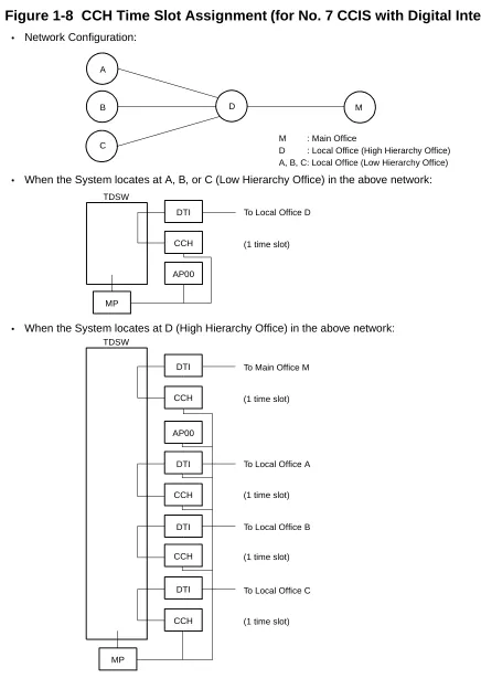
TIME SLOT ASSIGNMENT CONDITION
As shown in
Figure 1-6
, the 30-DTI/CCH cards uses the time slots on the basic highway 4.
However, the following conditions are required on the time slot assignment.
• The total number of time slots for all 30-DTI/CCH card must be less than 128 time slots or
less including all other application processor (AP) cards, which use the highway 4.
The 24-DTI card can use the time slot on both the basic and expanded highway 4 and 6.
Therefore, the total number of time slots for all 24-DTI card must be 256 time slots or less.
Figure 1-6 Accommodation of DTI/CCH into TDSW
T
D
SW
(1024 T
IM
E
S
L
O
T
S
)
FP0
FP1
FP2
FP3
DTI
AP00
FOR L/T CARDS: MAX. 512 TIME SLOTS PER SYSTEM
FOR BASIC HIGHWAY4: MAX. 128 TIME SLOTS PER SYSTEM 1 TIME SLOT/CARD
MAX. 128 TIME SLOTS
MAX. 128 TIME SLOTS
MAX. 128 TIME SLOTS
MAX. 128 TIME SLOTS
30-DTI: MAX. 31 TIME SLOTS/CARD
BRT
DCH
MAX. 2 TIME SLOTS/CARD (BRTA) MAX. 4 TIME SLOTS/CARD (2BRTC)
1 TIME SLOT/CARD
HW4
HW6
CCH 1 TIME SLOT/CARD
ATI 1 TIME SLOT/CARD
PRT 25 TIME SLOT/CARD
Time Slot Allocation for DTI Card
On each DTI card, the system recognizes the lowest and highest channel numbers to which trunk
numbers are assigned, and allocates time slots to all the channels between them. If trunk
numbers are assigned to nonconsecutive channels, the system also allocates time slots to
channels not assigned.
For example, as shown in
Figure 1-7
, when Channel 1 through Channel 10 have been assigned
by system data programming (CM07 YY=01) except Channel 5, the system allocates a total of
10 time slots for all ten channels. Therefore, to avoid allocation of unnecessary time slots, it is
recommended that consecutive channels be assigned on each DTI card.
Figure 1-7 Time Slot Allocation for DTI
DXXX
DXXX
DXXX NONE
DXXX
NONE DXXX
1
CH0 10
9
6
4 5
HIGHEST CHANNEL
10 TIME SLOTS ARE ALLOCATED EVEN WHEN CH5 IS NOT ASSIGNED.
Number of Time Slots Required for DTI/CCH Card
(1)
When the system is serving as a Lower Hierarchy Office within the network, 1 time slot is
allocated for setting up a fixed path between the DTI/ODT and the CCH as the common
signaling channel.
(2)
When the system is serving as a High Hierarchy Office within the network, 1 time slot is
allocated to the distant Main Office and distant Local Office for the common signaling
channel.
NOTE 1: A billing information from distant Local Office is transferred as follows.
AP00
→
MP
→
CCH
NOTE 2: When a common signaling data link is provided via a MODEM, the time slot for the
Figure 1-8
shows the CCH time slot assignment for CCIS with Digital Interface.
Figure 1-8 CCH Time Slot Assignment (for No. 7 CCIS with Digital Interface)
A
B
C
M
TDSW
DTI
CCH
AP00
MP
TDSW
DTI
CCH
AP00
DTI
CCH
DTI
CCH
DTI
CCH
M : Main Office
D : Local Office (High Hierarchy Office) A, B, C: Local Office (Low Hierarchy Office)
To Local Office D
(1 time slot)
To Main Office M
(1 time slot)
To Local Office A
(1 time slot)
To Local Office B
(1 time slot)
To Local Office C
(1 time slot) • Network Configuration:
• When the System locates at A, B, or C (Low Hierarchy Office) in the above network:
Figure 1-9
shows the CCH time slot assignment for No. 7 CCIS with Analog Interface.
Figure 1-9 CCH Time Slot Assignment (for No. 7 CCIS with Analog Interface)
TDSW
TDSW
M : Main Office
D : Local Office (High Hierarchy Office) A, B, C: Local Office (Low Hierarchy Office) •
Network Configuration:
•
When the System locates at A, B, or C (Low Hierarchy Office) in the above network:
•
When the System locates at D (High Hierarchy Office) in the above network: LDT/ODT
LDT/ODT
CCH MODEM
To Local Office D
(1 time slot)
LDT/ODT
LDT/ODT
CCH MODEM
To Main Office M
(1 time slot)
LDT/ODT
LDT/ODT
To Local Office A, B or C
CCH MODEM (1 time slot)
TDSW
LDT/ODT
LDT/ODT To Local Office D
(1 time slot)
TDSW
LDT/ODT
LDT/ODT To Main Office M
(1 time slot)
LDT/ODT
LDT/ODT
To Local Office A, B or C CCH MODEM
LDT/ODT
LDT/ODT
LDT/ODT
MODEM CCH
A
B
C
Table 1-4
shows the number of time slots for each of the cards required for No. 7 CCIS with Digital
Interface and
Table 1-5
shows the number of time slots for each of the cards required for No. 7
CCIS with Analog Interface.
Table 1-4 Number of Time Slots Required per DTI/CCH/AP00 Card
(for No. 7 CCIS with Digital Interface)
CARD
NUMBER OF TIME
SLOTS PER CARD
REMARKS
PN-24DTA-C
1-24
• Number of CCIS channels (the number of
CCH) + number of trunks assigned
PN-30DTC-A
1-31
PN-SC00
1
• For a distant Main Office
– Common Signaling Channel: 1 time slot
1
• For a distant Local Office
– Common Signaling Channel: 1 time slot
Table 1-5 Number of Time Slots Required per CCH/AP00 Card
(for No. 7 CCIS with Analog Interface)
CARD
NUMBER OF TIME
SLOTS PER CARD
REMARKS
PN-SC00
1
• For a distant Main Office
– Common Signaling Channel: 1 time slot
1
• For a distant Local Office
– Common Signaling Channel: 1 time slot
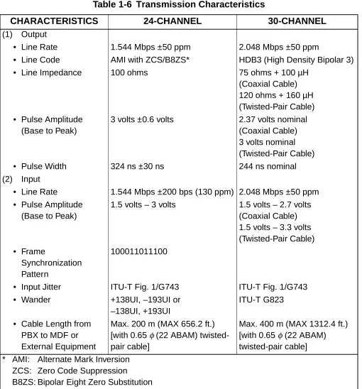
DTI SPECIFICATIONS
Transmission Characteristics
Table 1-6 Transmission Characteristics
CHARACTERISTICS
24-CHANNEL
30-CHANNEL
(1)
Output
• Line Rate
1.544 Mbps ±50 ppm
2.048 Mbps ±50 ppm
• Line Code
AMI with ZCS/B8ZS*
HDB3 (High Density Bipolar 3)
• Line Impedance
100 ohms
75 ohms + 100 µH
(Coaxial Cable)
120 ohms + 160 µH
(Twisted-Pair Cable)
• Pulse Amplitude
(Base to Peak)
3 volts ±0.6 volts
2.37 volts nominal
(Coaxial Cable)
3 volts nominal
(Twisted-Pair Cable)
• Pulse Width
324 ns ±30 ns
244 ns nominal
(2)
Input
• Line Rate
1.544 Mbps ±200 bps (130 ppm) 2.048 Mbps ±50 ppm
• Pulse Amplitude
(Base to Peak)
1.5 volts – 3 volts
1.5 volts – 2.7 volts
(Coaxial Cable)
1.5 volts – 3.3 volts
(Twisted-Pair Cable)
• Frame
Synchronization
Pattern
100011011100
• Input Jitter
ITU-T Fig. 1/G743
ITU-T Fig. 1/G743
• Wander
+138UI, –193UI or
–138UI, +193UI
ITU-T G823
• Cable Length from
PBX to MDF or
External Equipment
Max. 200 m (MAX 656.2 ft.)
[with 0.65
φ
(22 ABAM)
twisted-pair cable]
Max. 400 m (MAX 1312.4 ft.)
[with 0.65
φ
(22 ABAM)
twisted-pair cable]
* AMI: Alternate
Mark
Inversion
ZCS: Zero Code Suppression
Frame Configuration of 24-DTI
According to the AT&T Specifications for 24-channel transmission, there are two types of frame
configurations: 12-Multi Frame (D4) and 24-Multi Frame (ESF).
(1)
12-Multi Frame (D4)
The frame has 12-Multi Frames, and each Multi frame has a 24-channel PCM signal (8 bits/
channel) and an S bit (Super Frame Bit).
Figure 1-10
shows the frame configuration, and
Table 1-7
shows frame bit assignment.
Figure 1-10 Frame Configuration of 24-DTI (12-Multi Frame)
S
CH1 CH2 CH3 CH24
1 2 3 4 5 6 7 8 1 2 3 4 5 6 7 8 1 2 3 4 5 6 7 8 1 2 3 4 5 6 7 8
FRAME 1 FRAME 2 FRAME 3 FRAME 12
125 sm
*
The S-bit is the first bit in each frame.
*
Frames are repeated in the order shown above.
*
Frames 6 and 12 become signal frames.
Table 1-7 12-Multi Frame Bit Assignment
FRAME
No.
S BIT
BIT No. OF EACH
CHANNEL
(CH1-CH12)
SIGNAL
CHANNEL
TERMINAL
SYNCHRONIZATION
(FT)
SIGNAL
SYNCHRONIZATION
(FS)
INFORMATION
SIGNAL BIT
CONTROL
SIGNAL BIT
1
1
1-8
2
0
1-8
3
0
1-8
4
0
1-8
5
1
1-8
6
1
1-7
8
A
7
0
1-8
8
1
1-8
9
1
1-8
10
1
1-8
11
0
1-8
(2)
24-Multi Frame (Extended Super Frame <ESF>)
This frame has 24-Multi Frames and each Multi frame has a 24-Channel PCM signal (8 bits/
channel) and an S bit (Super Frame Bit).
Figure 1-11
shows the frame configuration, and
Table 1-8
shows frame bit assignment.
Figure 1-11 Frame Configuration of 24-DTI (24-Multi Frame)
TS0 TS1 TS2 TS15 TS16 TS17 TS30 TS31
FRAME 0 FRAME 1 FRAME 2 FRAME 3 FRAME 14 FRAME 15
Table 1-8 24-Multi Frame Bit Assignment
FRAME
No.
S BIT
BIT No. OF EACH CHANNEL
(CH1-CH24)
SIGNAL
CHANNEL
FRAME
SYNCHRONI-ZATION
4 Kbps
DATA
LINK
CRC
INFORMATION
SIGNAL BIT
CONTROL
SIGNAL BIT
1
m
1-8
2
CB1
1-8
3
m
1-8
4
0
1-8
5
m
1-8
6
CB2
1-7
8
A
7
m
1-8
8
0
1-8
9
m
1-8
10
CB3
1-8
11
m
1-8
12
1
1-7
8
B
13
m
1-8
14
CB4
1-8
15
m
1-8
16
0
1-8
17
m
1-8
18
CB5
1-7
8
C
19
m
1-8
20
1
1-8
21
m
1-8
22
CB6
1-8
23
m
1-8
*
The S-bit is the first bit in each frame.
*
Frames are repeated in the order shown above.
*
Frames 6, 12 and 24 become signal frames.
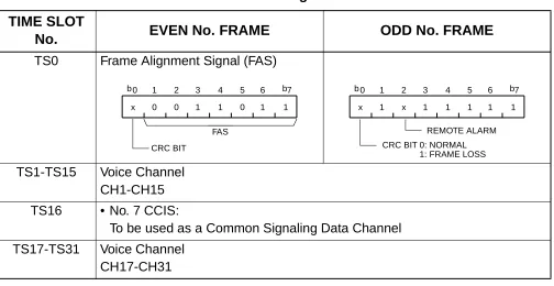
Frame Configuration of 30-DTI
Based on 30-channel transmission method of ITU-T Specification, the frame configuration
consists of 16-multi frame, each frame having 32 time slots.
Figure 1-12
shows the frame configuration, and
Table 1-9
shows the details of time slot
assignment.
Figure 1-12 Frame Configuration of 30-DTI
TS0 TS1 TS2 TS15 TS16 TS17 TS30 TS31
FRAME 0 FRAME 1 FRAME 2 FRAME 3 FRAME 14 FRAME 15
MODEM Specifications
The MODEM specifications required for No. 7 CCIS with Analog Interface are shown below.
• Synchronization
: Synchronous
• Data speed
: 1200 bps-9600 bps
• Transmission Mode
: Full Duplex
• Line
: 2/4 wire (Common Signaling Data Link via MODEM)
• Connection Type
: Leased
• Interface Condition
: ITU-T V24 and V28
Table 1-9 Time Slot Assignment of 30-DTI
TIME SLOT
No.
EVEN No. FRAME
ODD No. FRAME
TS0
Frame Alignment Signal (FAS)
TS1-TS15
Voice Channel
CH1-CH15
TS16
• No. 7 CCIS:
To be used as a Common Signaling Data Channel
TS17-TS31
Voice Channel
CH17-CH31
b 0
x 0 0 1 1 0 1 1 b 6 5 4 3 2
1 7
FAS
CRC BIT
b 0
x 1 x 1 1 1 1 1 b 6 5 4 3 2
1 7
REMOTE ALARM CRC BIT 0: NORMAL
SERVICE FEATURES
Table 1-10 List of No. 7 CCIS Service Features
SERVICE FEATURES
REMARKS
Attendant Camp-On with Tone Indication-CCIS
Attendant Controlled Conference-CCIS
NOTE 1
Brokerage-Hot Line-CCIS
Busy Verification-CCIS
Call Back-CCIS
NOTE 2
Call Forwarding-All Calls-CCIS
Call Forwarding-Busy Line-CCIS
Call Forwarding-Don’t Answer-CCIS
Call Forwarding-Intercept-CCIS
Call Forwarding-Override-CCIS
Call Transfer-All Calls-CCIS
Call Transfer-Attendant-CCIS
Calling Name Display-CCIS
Calling Number Display-CCIS
Centralized Billing-CCIS
Centralized Day/Night Mode Change-CCIS
NOTE 3
Centralized MAT-CCIS
NOTE 3
Consultation Hold-All Calls-CCIS
Data Line Security-CCIS
Elapsed Time Display-CCIS
Flexible Numbering of Stations-CCIS
Hands-Free Answer back-CCIS
Hot Line-CCIS
House Phone-CCIS
Incoming Call Identification-CCIS
Individual Attendant Access-CCIS
NOTE 4
LDN Night Connection-CCIS
Link Alarm Display-CCIS
Message Waiting Lamp Setting-Attendant-CCIS
NOTE 3
Message Waiting Lamp Setting-Station-CCIS
NOTE 3
Miscellaneous Trunk Access-CCIS
Miscellaneous Trunk Restriction-CCIS
Multiple Call Forwarding-All Calls-CCIS
Multiple Call Forwarding-Busy Line-CCIS
Multiple Call Forwarding-Don’t Answer-CCIS
Night Connection-Fixed-CCIS
Night Connection-Flexible-CCIS
Number Portability-CCIS
NOTE 3
Outgoing Trunk Queuing-CCIS
Paging Access-CCIS
Restriction from Outgoing Calls-CCIS
Single-Digit Station Calling-CCIS
Station Controlled Conference-CCIS
NOTE 1
Station-to-Station Calling-CCIS
Station-to-Station Calling-Operator Assistance-CCIS
Table 1-10 List of No. 7 CCIS Service Features (Continued)
NOTE 1: An attendant/extension of the IMX must be a conference leader.
NOTE 2: This service is available by the closed numbering plan.
NOTE 3: As a Local Office, this feature is available on the IVS.
NOTE 4: This service is available when the Attendant Console is provided at the IMX on the
network.
Toll Restriction-3/6 Digits-CCIS
Trunk Answer from Any Station (TAS)-CCIS
Trunk-to-Trunk Restriction-CCIS
Uniform Numbering Plan-CCIS
Voice Call-CCIS
Voice Mail Integration-CCIS
Table 1-10 List of No. 7 CCIS Service Features (Continued)
NETWORK STRUCTURE CONSIDERATIONS
Determining System Configuration
The configuration of the network and the number of lines (channels) should be determined, and
is dependent on the traffic between each office (PBX). For example, when the traffic between
Office A and Office C is high (as shown in the network of the following figure), Office A and Office
C should be connected by No. 7 CCIS directly.
Figure 1-13 Network Structuring
Determining Number of No. 7 CCIS Routes
When the system is a Main Office or a Tandem Office, two or more routes to other offices are
required.
• The maximum number of No. 7 CCIS routes is 8 per system.
Determining Type of Transmission Lines
The type of transmission lines available with the PBX are:
• Digital Interface (24-DTI/30-DTI)
• Analog Interface (LDT/ODT)
The Analog Interface is not suitable for a high-traffic network because the transmission speed of
the control signal is limited to a maximum of 9.6 Kbits per second (bps). A Digital Interface can
transmit control signals at up to 56 Kbps.
A
B
C
D
NO. 7 CCIS
Determining Which PBX Should Be Main Office
When using No. 7 CCIS, the following features require establishing a clear relationship between
the Main and Satellite offices:
• Centralized Attendant Service (CAS)
– Attendant Camp-On with Tone Indication-CCIS
– Busy Verification-CCIS
– Centralized Day/Night Mode Change-CCIS
For Centralized Day/Night Mode Change Service, the Main Office must be the IMX. This
feature can be set only from the Main Office IMX: The IVS’s Attendant Console cannot set
this feature. The IVS provides the feature when instructed by the Main Office.
• Centralized Billing-CCIS
• Centralized Fault Message
Main office: IMX only
The IVS can pass information, but cannot generate alarm information and send over CCIS.
• Centralized MAT-CCIS
For Centralized Fault Message, the PBX cannot generate its own fault message. It can only relay
a fault message from one office to another office.
Determining Point Code
Point Codes are used to distinguish an originating office and destination office in the No. 7 CCIS
network. A Point Code is assigned in each office in the No. 7 CCIS network. The following
considerations are required when deciding the Point Code.
(1)
The same Point Code cannot be assigned to more than one office.
(2)
A single Point Code must not be assigned to each CCIS channel in the same system. When
a system has two or more CCH, the same Point Code (originating) has to be assigned to all
CCH in a system.
(3)
The maximum number of Point Codes is 256. (Only 256 offices can be connected in the
same network.)
For example: Point Code Assignment
When Office A and Office C are IMX and Office B OFFICE B
is a PBX, a fault message from Office A can be
OFFICE C OFFICE A
NO. 7 CCIS NO. 7 CCIS
PRINTER FOR FAULT MESSAGE
printed out at the printer located in Office C.
PC: 00001
CCH0 A
PC: 00002
B
PC: 00003
C CCH1 CCH1
CCH0
A/B/C: Office (PBX)
• Data Assignment of Office A
• Data Assignment of Office B
• Data Assignment of Office C
Command Code 1st Data 2nd Data Remarks
CMA7 YY=01 CMA7 YY=02 CMA7 YY=01 CMA7 YY=02
0 0 1 1
00001 00002 00001 00003
Assign the Originating Point Code and the Destination Point Code for CCH0. Assign the Originating Point Code and the Destination Point Code for CCH1.
Command Code 1st Data 2nd Data Remarks
CMA7 YY=01 CMA7 YY=02
0 0
00002 00001
Assign the Originating Point Code and the Destination Point Code for CCH0.
Command Code 1st Data 2nd Data Remarks
CMA7 YY=01 0
0
00003 00001
Determining CCH Link to Send Messages
Each system MP must be programmed with the proper information indicating to which CCH (in
its own system) every other office in the network is connected. This is required for providing
inter-office services such as Attendant Camp-On, Call Back, and Busy Verification when using CCIS.
In each system, CMA8 is used to inform the local MP which system is connected through which
CCH. This is extremely important, not only for where two switches are connected to each other,
but also for networks in which tandem signaling is used.
Example 1:
• Data Assignment of Office A
• Data Assignment of Office B
Command Code 1st Data 2nd Data Remarks
CMA8 00002
00003 00004
0 0 0
Assign the data to make a CCH link with Office B via CCH0.
Command Code 1st Data 2nd Data Remarks
CMA8
00001
00003
00004
1
0
0
Assign the data to make a CCH link with Office C via CCH0, and make a CCH link with Office A via CCH1.
A
B
PC: 00001
CCH0
A/B/C: Office (PBX)
CCH : Common Channel Handler
PC : Point Code C
D PC: 00002
PC: 00003
PC: 00004
CCH1
CCH1 CCH0
• Data Assignment of Office C
• Data Assignment of Office D
Example 2:
In this example, there are two connection patterns from Office A to Office D, A-B-D and
A-C-B-D. Office A’s first choice route in the LCR (Least-Cost Routing) Route Pattern Table would be
CCH0 (whatever route the voice channel is assigned to).
The second choice would be to the voice route associated with CCH1, which is connected to
Office C. At Office C the programming is set up to call and signal Office B, which then routes the
call to Office D.
• Data Assignment of Office A
Command Code 1st Data 2nd Data Remarks
CMA8 00001
00002 00004
1 1 0
Assign the data to make a CCH link with Office D via CCH0, and make a CCH link with Office B via CCH1.
Command Code 1st Data 2nd Data Remarks
CMA8 00001
00002 00003
0 0 0
Assign the data to make a CCH link with Office C via CCH0.
Command Code 1st Data 2nd Data Remarks
CMA8 00002
00003 00004
0 1 0
Assign the data to make a CCH link with Office B via CCH0 and make a CCH link with Office C via CCH1.
A B
C
PC: 00001 PC: 00002
CCH0 CCH0
CCH1
CCH0
PC: 00003 A/B/C/D: Office (PBX) CCH : Common Channel
Handler PC : Point Code
D PC: 00004
CCH2 CCH0
CCH1
• Data Assignment of Office B
• Data Assignment of Office C
• Data Assignment of Office D
Determining Numbering Plan
The Uniform Numbering Plan is used for the numbering plan in the No. 7 CCIS network. The
Uniform Numbering Plan is provided by the Least-Cost Routing (LCR) feature, and there are two
types of plans described below.
• Station Number (Closed Numbering)
• Office Code and Station Number (Open Numbering)
When an outgoing call is placed through a CCIS link, an originating station number (Office Code
and Station Number) and a terminating Station Number are transmitted across the link to the
destination office. The originating station number consists of the office number assigned in
CMA7 YY=06 and the station number assigned in CM10 for the station time slot. The terminating
station number consists of the dialed number and the data assigned in CM8A (any LCR changes
to the number dialed).
Command Code 1st Data 2nd Data Remarks
CMA8 00001
00003 00004
0 1 2
Assign the data to make a CCH link with Office A via CCH0 make a CCH link with Office C via CCH1 and make a CCH link with Office D via CCH2
Command Code 1st Data 2nd Data Remarks
CMA8 00001
00002 00004
0 1 0
Assign the data to make a CCH link with Office A via CCH0 and make a CCH link with Office B via CCH1.
Command Code 1st Data 2nd Data Remarks
CMA8
0000100002 00003
0 0 0
Figure 1-14 Example of Station Number (Closed Numbering)
Figure 1-15 Example of Office Code and Station Number (Open Numbering)
53xx
53xx
54xx
54xx 52xx
52xx
A
B
C Station Numbering
(Closed Numbering):
• When originating a call from Office A to Office C
54xx
Station Number
Office Location Number
A
B
C Office Code and Station Number
(Open Numbering):
• When originating a call from Office A to Office C
Station Number
Access Code
xxxx
11
12
13
Office Code
13-
8-xxxx
xxxx
xxxx xxxx
xxxx
Limitations on developing the Uniform Numbering Plan are as follows:
(1)
Station Number (Closed Numbering)
• The dialing number must be formed as follows:
• When providing 3-digit or 4-digit station numbering within the No. 7 CCIS network, the data
assignment of the Originating Office Number (CMA7 YY=06) is not necessary because the
Originating Office Number is included in the originating station number.
• LCR Group 3 (CM20>A129) must be used for assigning an LCR access code.
(2)
Office Code and Station Number (Open Numbering)
• The dialing number must be formed as follows.
XXXXXXXX
Station Number (Max. 8 digits)
Office Location Number (Max. 2 digits)
a1 a2 b1 b2 b3 c1 c2 c3 c4 c5 c6 c7 c8
Station Number (c) Office Code (b)
Access Code (a)
• LCR Groups 0-3 (CM20>A126-A129) can be used for assigning an LCR access code.
• When providing a pseudo dial tone to alter the dialing access code, LCR Groups 0-2
(CM20>A126-A128) must be used.
Example 1: Station Number (Closed Numbering)
• When the office location number is distinguished by the 1st or 2nd digit of the dialed station
number:
• Data Assignment of Office A
Command Code 1st Data 2nd Data Remarks
CM20 Y=0 CM20 Y=0
CM8A YYYY=A000 CM8A YYYY=4007 CM8A YYYY=0000 CM8A YYYY=5000 CM8A YYYY=5000 CM10
CMA7 YY=06 CM85 Y=7
51 52 3 52
1 100 153 XXX
0 52
804 A129 4007 0000 00010
CCC CCC 51XX NONE
04
4-digit station LCR Group 3
Area code Development Pattern No. 7 Route Pattern 000
Route 10 access by dialing 52XX No digit addition
No digit deletion
Originating station number No originating office number
Maximum number of digits dialed “4”
51xx 52xx
NO. 7 CCIS
• When the office location number is distinguished by the 3rd digit of the dialed station
number:
• Data Assignment of Office A
Command Code 1st Data 2nd Data Remarks
CM20 Y=0
CM8A YYYY=A000 CM8A YYYY=4007 CM8A YYYY=4007 CM8A YYYY=0000 CM8A YYYY=5000 CM8A YYYY=5000 CM10
CMA7 YY=06 CM85 Y=5
5 3 512 513 1 100 153 XXX
0 513
A129 4007 8004 0000 00010
CCC CCC 512X NONE
04
LCR Group 3
Area Code Development Pattern No. 7 4-digit Intra-Office Station
Route Pattern 000
Route 10 access by dialing 513X No digit addition
No digit deletion
Originating station number No originating office number
Maximum number of digits dialed “4”
512x 513x
NO. 7 CCIS
Example 2: Office Code and Station Number (Open Numbering)
• Data Assignment of Office A
Pattern 1 (Used when receiving pseudo dial tone after dialing access code.)
Command Code 1st Data 2nd Data Remarks
CM20 Y=0 CM8A YYYY=A000 CM8A YYYY=4005 CM8A YYYY=4005 CM8A YYYY=4005 CM8A YYYY=0000 CM8A YYYY=5000 CM8A YYYY=5000 CM8A YYYY=9000 CMA7 YY=06 CM10 CM85 Y=5 8 0 50 51 52 1 100 153 0 0 XXX 51 52 A126 4005 8000 0000 0000 00010 00 CCC 8 820 21XX 07 07
LCR Group 00
Area Code Development Pattern No. 5 Intra Office Termination
Route Pattern No. 000 Route Pattern No. 000
Route 10 access by dialing 31XX/34XX Digit Addition Pattern No. 00
No digit deletion Addition of digit “8” Originating office number Originating station number
Maximum number of digits dialed “7”
21xx 34xx A
52 51 C B 50 31xx
Access Code: 8
• Pattern 2 (Used when not receiving pseudo dial tone.)
Command Code 1st Data 2nd Data Remarks
CM20 Y=0
CM8A YYYY=A000 CM8A YYYY=4007 CM8A YYYY=4007 CM8A YYYY=4007 CM8A YYYY=0000 CM8A YYYY=5000 CM8A YYYY=5000 CMA7 YY=06 CM10
CM85 Y=5
8 3 850 851 852 1 100 153 0 XXX
851 852
A129 4007 8000 0000 0000 00010
CCC CCC 820 21XX
07 07
LCR Group 3
Area Code Development Pattern No. 7 Intra Office Termination
Route Pattern No. 000 Route Pattern No. 000
Route 10 access by dialing 851XXXX/852XXXX No digit addition
No digit deletion
Originating office number Originating station number
Determining Route Advance
In a No. 7 CCIS network, the system can automatically route outgoing calls over an alternate
facility.
Example 1: When the number of tie line routes is two or more:
CONDITIONS:
• Office Code and Station Number (Open Numbering)
• Access Code: 8
• Office Code:
50 (Office A)
51 (Office B)
52 (Office C)
53 (Office D)
• Connection Pattern from A to D
1st Choice:
A
→B
→D
2nd Choice:
A
→C
→B
→D
Data Assignment of Office A:
Command Code 1st Data 2nd Data Remarks
CM20 Y=0 CM8A YYYY=A000 CM8A YYYY=4007 CM8A YYYY=0000 CM8A YYYY=0000 CM8A YYYY=5000 CM8A YYYY=5000 CMA7 YY=06 CMA7 YY=06 CM10 8 3 853 1 2 100 153 0 1 XXX A129 4007 0000 00010 00012 CCC CCC 820 820 21XX
LCR Group 3
Area Code Development Pattern No. 7 Route Pattern 000
LCR Pattern 000, Route 10 LCR Pattern 000, Route 12 No digit addition
No digit deletion
Originating office number (to Route 0) Originating office number (to Route 1) Originating station number
21xx 35xx A B D
C RT10
RT12
50 51 53
Example 2: When route advance to C.O. is required because the desired tie lines are all busy:
CONDITIONS:
• Office Code and Station Number (Open Numbering)
• Access Code: 8
• Office Code:
50 (Office A)
51 (Office B)
• Connection Pattern from A to B
1st Choice:
via No.7 CCIS
2nd Choice:
via C.O. line
Data Assignment of Office A:
Command Code 1st Data 2nd Data Remarks
CM20 Y=0 CM8A YYYY=A000 CM8A YYYY=4007 CM8A YYYY=0000 CM8A YYYY=0000 CM8A YYYY=5000 CM8A YYYY=5000 CM8A YYYY=5001 CM8A YYYY=5001 CM8A YYYY=9000 CMA7 YY=06 CM10 CM85 Y=7 8 3 851 1 2 100 153 100 153 0 0 XXX 851 A129 4007 0000 00010 00101 CCC CCC 00 03 516753 821 21XX 07
LCR Group 3
Area Code Development Pattern No. 7 Route Pattern 000
LCR Pattern 000, Route 10 LCR Pattern 001, Route 01 No digit addition
No digit deletion
Digit Addition Pattern No. 00 Reading 3 digits deletion Digit code to be added: 516753
Originating office number (to Route 10) Originating station number
Maximum number of digits dialed “7”
21xx 31xx A B
RT10
50 51
RT12
NO. 7 CCIS C.O.
Example 3: When route advance to one’s own office C.O. is required and the tie line route of the
tandem office connected through CCIS are all busy:
CONDITIONS:
• Tie Line between A and B: Idle
• Tie Line between B and C: Busy
• The other conditions are same as in Example 2.
Data Assignment of Office A:
The other data assignments are the same as in Example 2.
Command Code 1st Data 2nd Data Remarks
CM08 372 0
A
RT10
50 51
RT1
NO. 7 CCIS
C.O.
DID (LDN: 516753-xxxx)
NO. 7 CCIS 52
Network Construction with IMX
The Tenant Number and the Trunk Restriction Class are different between the PBX and the IMX
as indicated below.
PBX
IMX
• Tenant No.
00-63
01-255
(CM12 YY=04, CM30 YY=01)
• Trunk Restriction class
1-8
1-15
(CM12 YY=01)
Based on these differences, care must be taken to ensure that proper programming is completed
to accommodate the differences between the PBX and the IMX.
(1)
In the PBX, station and trunk assignment to tenants must be to a tenant number equal to
01 or higher. (Do not use Tenant 00.)
(2)
For Attendant Console calls, the tenant number transmitted to the destination PBX is equal
to the Attendant Group (0-3) to which the attendant is assigned in CM60 YY=00. Remember
that Tenant 00 is not available in the IMX, so an Attendant Group of 1-3 must be used.
(3)
For ensuring proper restriction classes throughout the network, programming in the PBX
allows equating the restriction classes of the PBX with the restriction classes available in
the IMX. For details, refer to
"Deluxe Traveling Class Mark-CCIS" on Page 188
.
INSTALLATION
PRECAUTIONS
Static Electricity Guard
You must wear a grounded wrist strap to protect circuit cards from static electricity.
Figure 2-1 Static Electricity Guard
• WHEN PLUGGING/UNPLUGGING A CIRCUIT CARD
• WHEN HOLDING A CIRCUIT CARD
PBX
WRIST STRAP
FRAME GROUND SCREW
CARD FRONT
Figure 2-2 Static Electricity Guard
• WHEN MAKING A SWITCH SETTING ON A CIRCUIT CARD
• WHEN CARRYING A CIRCUIT CARD
The mark shown below is attached to the sheet for the work in which circuit cards are handled.
When engaging in such work, the installer must be careful not to cause damage by static
electricity.
WEAR A WRIST STRAP AND PERFORM THE WORK ON A GROUNDED
CONDUCTIVE WORK SURFACE. CIRCUIT
CARD
WHEN CARRYING A CIRCUIT CARD AROUND, KEEP THE CARD IN A CONDUCTIVE POLYETHYLENE BAG. CIRCUIT
CARD CONDUCTIVEPOLYETHYLENE
BAG
ATTENTION
ContentsStatic Sensitive Handling
CAUTION
You must hold the edge of a circuit card when plugging or unplugging the circuit card. If you
touch another area, you may be exposed to hazard voltages.
CARD FRONT
NEVER TOUCH THE COMPONENTS OR SOLDERED SURFACE WITH BARE HANDS.