Performance Analysis of OTDM Using
Different Modulators and Modulation
Formats at 160Gbps
Dr. Ranjit Kaur1, Anjali2
Professor, Dept. of ECE, Punjabi university Patiala, India1
M.Tech Scholar, Dept. of ECE, Punjabi university Patiala, India2
ABSTRACT: In communication system higher speed data transmission is always required. For higher bit rate and flexible bandwidth Optical time division multiplexing (OTDM) is one of the best system. In this paper the simulation is carried out by using the four channel OTDM system with the use of Return to zero (RZ) and Modified Duo-binary Return-to-Zero (MDRZ) modulation format. System is evaluated on reception by using both Electro-absorption modulator (EAM) and Mech-zehnder modulator (MZM) in single and cascaded configurations and conclusion have been drawn by demultiplexing from 160 Gb/s to 40 Gb/s over a 2400 km with acceptable bit error rate (BER) and Quality factor (Q) value. The simulation work is done in optisystem 7.0 suite software.
KEYWORDS: MDRZ, OTDM, Q Factor, EAM, MZM, DCF.
I. INTRODUCTION
Optical Fiber system plays a vital role in optical communication system. The optical carrier signal has very great probable transmission bandwidth than metallic cable systems. Development of different multiplexing technology sanctioned very high capacity optical fiber communication networks that offer transmission over many thousands of kilometers without using any electronic repeater [1]. Optical technology plays a crucial role in the decrease of the necessity of the electronic processing by steering the traffic in the optical domain direct to the target in order to avoid the need for large electronic processors at intermediate network positions [2]. There is an increasing insists for extended transmission capacity. This demand can be fulfill by OTDM technology. In OTDM, a data stream of high bit rate is constructed directly by time division multiplexing various optical streams of lower bit rate [3]. At the receiver side, demultiplexing of the very high bit-rate optical signal to several lower bit-rate signals is performed before detection and conversion into the electrical field. The time-division multiplexing is a completely digital technique and hence it is compatible with the idea of an all-digital network which combines switching and transmission. Moreover, OTDM provides system flexibility and it is capable to allocation of bandwidth in to different baseband channels. In this only a single transmitter laser is required for all the channels.
single wavelength channel [9]. The performance of OTDM system has been measured on the basis of Q-factor and BER[10].The BER is basically the ratio of number of bit errors to the total number of transmitted bits. The Q-factor determines the opening of the eye. More the eye opening more the Q-factor and better is the signal strength [11]. This paper demonstrates the comparison between different modulators and modulation formats at receiver side. This paper is structured as follow: Section II presents the general structure of OTDM. Section III shows the simulation setup of different modulators and modulation formats. In section IV and V results and conclusions are drawn.
II. GENERAL OTDM SETUP
The block diagram of general OTDM system is shown in Fig.1. OTDM transmission system consists of three parts: transmitter, fibre link and receiver. The transmitter block consists of Laser sources, modulators and multiplexer. The fibre span contains optical amplifiers, DCF and transmission fibre. The receiver block consist of synchronization/timing extraction circuit and channel de-multiplexer. The PRBS block generates multiple pattern output at a bit rate bits/sec. All the channels from CW laser are operating at same wavelength of 1552nm with line width 10MHz and 0 dm power. Before being multiplexed together, each signal is followed by an optical delay of 0 ns, 2 ns, 4 ns and 6 ns and then fed to corresponding 4×1 multiplexer. The OTDM signal travels over a fibre. After travelling through fibre, the pulse gets broadened due to chromatic dispersion. So to compensate dispersion, fibre span consists of DCF to make the total dispersion zero. After then it is de-multiplexed at the receiver side.
EDFA DCF EDFA
Fig.1. General Overview of OTDM link.
The receiver consists of clock recovery, photo detector, filter and BER analyzer. After that 160 Gbps optically modulated signal is splitted into four 40 Gbps signals and fed to the demodulator. The optical signal is then converted into electrical domain with the help of PIN diode photo detector having responsivity of 1 A/W and dark current 1 nA. The signal noise is then filtered out using low pass filter with cut-off frequency 0.75*Bit rate. The BER analyzer is used to measure Q value and BER.
III. SIMULATION SETUP
A continuous wave laser source is used with 10 db line width, which is operating at 193.1 THz (1552.5243nm). The transmitter consists of fork 1*4 use to split the 40Gbps channel into four channels. Four channels from the Continuous Wave (CW) laser are MDRZ modulated with a different pseudo-random bit sequence (PRBS) generator. Among the four splitted channels each channel espouse from optical delay. Then it fed through the 4*1 power combiner. An OTDM signal is generated and passes through the 25 km single mode fiber with dispersion of 17 ps/nm/km. Then an erbium doped fiber amplifier (EDFA) is employed with gain of 5 dB.
Laser Source
Clock PRBS
Generator
Modulator Combiner
Fig.2. Simulation setup for 160Gbps OTDM with RZ modulation format.
Fig.2.1. Simulation set up of 160Gbps OTDM with MDRZ modulation format.
Fig.2.2 Simulation set up of MDRZ-OTDM with cascaded MZM modulator.
EDFA uses 10 dBm of power for its operation. So to compensate the dispersion, fiber length consists of Dispersion Compensating fiber (DCF) to make the total dispersion null. The length of DCF is 10km with dispersion -85 ps/nm/km. At the receiver side EAM or MZM are used with PRBS and RZ pulse generator.PIN photo detector is use with responsivity of 1 A/W and dark current 1 nA. Low Pass filter is employed with cut off frequency of 0.75*Bit rate. The BER analyzer is use to measure Q value and the BER.
IV. RESULTS AND DISCUSSION
(EAM) or Mach-Zehnder Modulator (MZM). The optical spectra for the RZ OTDM and MDRZ OTDM at 0 dbm input power at 193.1 THz is shown in fig 3 and fig.3.1.
Fig.3. Power spectrum at 193.1 THz for MDRZ OTDM
Fig.3.1.
Power spectrum at 193.1 THz for RZ OTDM system with 10MHz line widthIt has narrow spectral width as compare to the fig 3 in fig 3.1. More is the spectral width the more dispersion raise. So MDRZ OTDM system gives better performance than that of RZ OTDM system.
In OTDM system, Q value is one of an important parameter that is used to measure the performance of the system. The graphs are plotted between the Q value and the transmission distance by varying different parameters.
Table 1 Comparison table of performance between RZ OTDM and MDRZ OTDM system with single MZM modulator at receiver
Distancein km RZ OTDM MDRZ OTDM
120 8.6062 18.0012
240 7.01829 17.625
360 5.35574 16.9949
480 4.40761 15.9546
600 3.62724 14.7446
720 3.07502 13.445
By varying the distance travel by optical signal the Q factor value also changes. Between the RZ OTDM and MDRZ OTDM the MDRZ OTDM gives the most effective result in Fig.3.2.
The RZ OTDM signal travel approximately 350 Km and MDRZ OTDM can travel upto 2100 Km with acceptable Q factor value with single MZM modulator at receiver side.
Fig.3.3. Q factor performance after demultiplexing 160 to 40 Gbps with single and cascaded modulator.
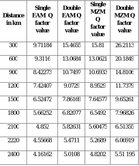
Table 2 Q factor values by varying transmission distance for MDRZ OTDM system with single and cascaded EAM and MZM modulators.
When 0 dbm input power is applied then there are different Q factors values observed at different transmission distance for single and cascaded modulators in fig 3.4. It is clear that double MZM modulator gives best performance among them. And travel maximum achievable distance with acceptable Q value. Among them single EAM give the worst performance it travel only upto 1800 Km with acceptable limit. Single MZM and Double EAM gives approximately same performance.
Fig 3.4. Q factor performance at the same transmission distance by varying the input power for single and cascaded modulators.
Distance in km
Single EAM Q
factor value
Double EAM Q
factor value
Single MZM
Q factor
value
Double MZM Q
factor value
300 9.71184 15.4655 15.81 26.2113
600 9.3116 13.0684 13.0621 20.1849
900 8.42273 10.7497 10.6933 14.8106
1200 7.42407 9.0729 8.9529 11.7379
1500 6.52472 7.86169 7.64577 9.65261
1800 5.66252 6.82077 6.5492 7.96826
2100 4.852 5.82631 5.60475 6.51355
2220 4.55668 5.4711 5.2689 6.06919
Among all the input powers the 0 dBm gives the best Q factor value as shown in fig 3.5. And among the modulators, double MZM gives the best result at 0 dBm input power. As we goes on increasing the power then the Q factor value is decreasing, but in case of single MZM at 5 dBm the value of Q factor is 0 and at 10 dBm the Q factor value is 3.55877.
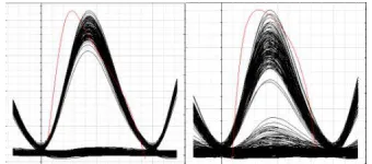
Fig.3.5. Eye diagrams at min and max transmission distance for Single EAM
Fig.3.6. Eye diagrams at min and max transmission distance for Single MZM
Fig.3.7. Eye diagrams at min and max transmission distance for Double EAM
Fig 3.8. Eye diagrams at min and max transmission distance Double MZM
For the single and cascaded modulators Eye diagram are shown in fig. In fig 3.5. maximum achievable transmission distance of 1800 km on which eye height has acceptable value, i.e noise has not severe effect on the optical signal transmission. The eye diagram for single MZM and the double EAM are the approximately similar pattern at the maximum achievable distance of 2100 km. Best eye pattern among is of double MZM with maximum achievable distance of 2400 km.
V. CONCLUSION
Secondly, compared the performance of MDRZ OTDM system by using single and cascaded modulators at receiver end. Among them the single EAM, double EAM, single MZM and double MZM modulator the double MZM gives the best result of transmission distance 2400 km without using regenerator with an acceptable Q factor value 5.51595 and BER 4.42527*10-9 at 0dbm input power.
REFERENCES
[1] A. E. Willner, Z. Pan, M. I. Hayee, “Major Accomplishments in 2010 on Optical Fiber Communication,” IEEE Photonics Journal, Vol. 3, No. 2, pp. 320-324, April 2011.
[2] Dave M. Spirit, Andrew D, Ellis, and Pete E. Barnsley, “Optical Time Division Multiplexing: Systems and Networks” IEEE Communications Magazine, Vol. 32, No.12, pp. 56-62, December 1994.
[3] Rodney S. Tucker, Gad I. E. Isenstein and Steven K. Korotky, “Optical Time-Division Multiplexing for very high bit-rate transmission,” Journal of Light wave Technology, Vol. 6, No. 11, pp. 1737-1749, November 1988.
[4] J. D. Moores, J. Kom, K. L. Hall, S. G. Finn, and K. A.
Rauschenbach, “Ultrafast Optical TDM networking extension to the wide area”, IEICE Trans. Commun., E82-B, pp. 209-221, 1999.
[5] K. L. Hall and K. A. Rauschenbach, “All-optical Buffering of 40-Gb/s data packets,” IEEE Photonics Tech. Lett., Vol. 10, No. 3, pp. 442-444, March 1998.
[6] K. Suzuki, K. A. Iwatsuki, S. Nishi, M. Saruwatari, and T. Kitoh, “160 Gbit/s Sub-picosecond transform-limited pulse signal generation utilizing adiabatic soliton compression and optical time-division multiplexing,” IEEE Photon. Technol. Lett., Vol. 6, No. 3, pp. 352-354, March 1994. [7] T. J. Xia, Y. H. Kao., Y. Liang, J. W. Lou, K. H. Ahn, O. Boyraz, G. A. Now, A. A. Said and M. N. Islam, “Novel Self-synchronization Scheme for high-speed Packet TDM networks,” IEEE Photon Tech. Lett., Vol. 11, No. 2, pp. 269- 271, February 1999.
[8] T. Durhuus, B. Mikkelsen, C. Joergensen, S. L. Danielsen, and K. E. Stubjkaer, “All Optical Wavelength Conversion by Semi-conductor Optical Amplifiers,” J. Lightwave Technol., Vol. 14, No. 6, pp. 942-954, June 1996.
[9] Hans-Georg Weber, Reinhold Ludwig, Sebastian Ferber, Carsten Schmidt-Langhorst, Marcel Kroh, Vincent Marembert, Christof Boerner, and Colja Schubert, “Ultrahigh-Speed OTDM-Transmission Technology”, JOURNAL OF LIGHTWAVE TECHNOLOGY, VOL. 24, NO. 12, DECEMBER 2006.
[10] W. Yu, L. Huo, D.LU, C. Lou” A Novel Optical Picoseconds NRZ to RZ format converter with simultaneous wavelength Multicasting Using a Single Stage Mach Zehnder Modulator” Optic Communication, Vol. 285, pp.4302-4306, July 2012.