User Manual
Portable Radios
1
2
3
4
5
6
7
8
9
0
#
SIGNAL TX LOW CTCSS BATT
SCAN SAVE
MEM OFS MODE
SQL LOW SCAN SIG
N-DEL STEP PL
A B C D
3
AP73 Quick Reference
Basic Operation...
Turning Radio On/Off: Rotate On/Off and Volume Knob clockwise / anti-clockwise.
Adjusting Volume: Press Monitor Button and adjust On/Off and Vol-ume Knob to comfortable volVol-ume level.
Setting High/Low Power Output Level: Press to toggle power lev-els; ‘LOW’ indicator is on when radio is set for Low Power output level. Transmitting: Select the desired channel / frequency. Make sure channel is free then press PTT to talk, release to listen. ‘TX’ indicator lights up. Locking/Unlocking Radio’s Function: Press for 2 seconds to lock / unlock Keypad and Selector Knob. LCD displays when locked. Changing Squelch Modes: Press to toggle between Carrier (‘CTCSS’off ), Coded( ‘CTCSS’ on ) and Signalling (‘CTCSS’ flashing) squelch.
Setting Squelch Level: Press then rotate Selector Knob clockwise / anti-clockwise to increase / decrease squelch level. Press any key to accept.
Selecting Receive PL/DPL Squelch: Press until✰ xxx is shown. Rotate Selector Knob to the desired active Receive PL/DPL code. Press any key to accept.
Selecting Transmit PL/DPL Squelch: Press until✰ xxx is shown. Press to get✰ xxx. Rotate Selector Knob to the desired active Transmit PL/DPL code. Press any key to accept.
Selecting Mhz/Memory Mode: Press to toggle between Mhz (fre-quency displayed) and Memory (channel number displayed) mode.
TX LOW CTCSS SCAN BATT SAVE SIGNAL + -# STEP P OFS MODE
L A 73 Push-to-Talk (PTT) Button Monitor Button Antenna Connector
Toggle Light / Enter and Parameter
Selector Knob On / Off andVolume Knob
MHz Operation...
Selecting Frequency Step Size: Press until current frequency size is shown. Rotate Selector Knob to the desired frequency step size then press any key to accept.
Selecting Receive Frequency: In Mhz mode, enter desired frequency (whole or❖part) or/and rotate Selector Knob to the required frequency. Selecting TX Offset: Press to toggle betweenno offset, standard positive offset (‘+’ displayed), standard negative offset (‘-’ displayed) and user-defined TX frequency (“+ -” displayed).
Programming User-Defined TX Frequency: Press until ‘+ -’ is shown. Enter desired TX frequency (whole or❖part) or/and rotate Selec-tor Knob to the required frequency then press Toggle Light / Enter and Parameter Transfer Button.
Memory Mode Operation...
Selecting Memory Channel: In Memory mode, rotate Selector Knob. Programming Memory Channel: In MHz mode, select the desired fre-quency, type of offset and offset frequency then press Toggle Light / Enter and Parameter Transfer Button until✰ xxx is shown. Rotate Selector Knob to select the desired memory channel then press Toggle Light / Enter and Parameter Transfer Button to accept.
Loading Memory Channel: In Memory mode, rotate Selector Knob to the desired memory channel then press Toggle Light / Enter and Param-eter Transfer Button to accept.
Scan Operation...
Scanning Frequency Range/Memory Channel : In Mhz/Memory mode, press to begin scanning the preprogrammed frequency range/chan-nel. ‘SCAN’ indicator flashes when scanning is in progress, and lights up continuously when it is receiving a signal.
Transmitting During Band Scanning: Press PTT when scan is locked at a frequency.
Deleting Nuisance Channel: With radio locked onto unwanted channel, press until you hear two beeps.
✰
DTMF Telephone Interconnect...
Placing a Telephone Call: Press and hold PTT and dial access code (or, if radio has preprogrammed code, press followed by ). Release PTT and wait for dial tone. If successful, press and hold PTT, then dial phone number (or, if radio has preprogrammed phone number, press followed by number button that stores phone number). Press PTT to talk, release to listen. To hang up, press and hold PTT, then dial deaccess code (or, if radio has preprogrammed code, press followed by ). Last Number Redial: Once you have accessed the telephone network, press and hold PTT, then press followed by (only works with manual entered phone number).
Storing a Phone Number or Access/Deaccess Code: Press and hold
until LCD displays (with a flashing cursor). Enter a phone number location (1 to 9), or press / to enter access / deaccess code. Enter the phone number (up to 12 digits), or access/deaccess code (up to 8 digits). Press Toggle Light/Enter and Parameter Transfer But-ton to accept.
Displaying a Stored Number: To view stored phone number, press , followed by a phone number location (1 to 9). To view access/deaccess code, press followed by / . Press followed by to view the last manually dialled number.
✣
Voice Selective Call (Optional)...
Receiving a Voice Selective Call: When radio decodes a Voice Selective Call, LCD indicates the type of SelCall message being received: (Individual Call), , (Group Call), or (All Call).
Sending a Voice Selective Call: Press and hold PTT, then dial the required ID. Release PTT and wait for a response.
Special Programming Mode (SPM)...
Entering SPM: Hold down while turning on the radio. Only release after the radio sounds a ringing SPM start-up tone.
Exiting a Menu Item: Select another menu item by rotating Selector Knob. NOTE: This aborts the phone access / deaccess codes entry, if Toggle Light/Enter and Parameter Transfer Button is not pressed first. Exiting Special Programming mode: Turn radio off, then on again.
The following table provides a complete list of the available parameters and their programming procedures (items with similar procedures are grouped together).
First go to SPM then rotate Selector Knob to the desired menu item (refer to the SPM display column below).
SPM Browse Menu
SPM Dis-play
SPM Browse Menu Item
To Edit
Edit Channel Scan List
Press or to scroll through the channels (01 to 20). Press Toggle Light/Enter and Parameter Change Button to toggle status of channel.
Erase Single Chan-nel from Memory
Notes...
✰
xxx represents a number. ❖
Press Toggle Light / Enter and Parameter Transfer Button to commit partially entered frequency.
✣
Radio must be equipped with an optional DTMF Decode Option board. §SelCall Tone Status only displays when an option board is installed.
✰
✰ Edit Phone Access /
Deaccess Code
Press or to enter into edit mode. to erase unwanted digits. Enter new code.
Edit PTT ID
Edit Acknowledge-ment / Individual / Group / All Call IDs
Press or to enter into edit mode. to erase unwanted digits. Enter new ID.
Edit Time-Out Timer
Press or .
§Set SelCall Tone
Status (‘On’ or ‘Off’)
Set Sidetones Sta-tus (‘On’ or ‘Off’).
Set Alert Tone Vol-ume (‘Off’ or ‘On’).
Press or to toggle between the available states.
Sidetones Status affects DTMF sidetones only. If Alert Tone Volume is set to ‘off’,all radio alert tones are disa-bled.
Set Battery Saver Status (‘Off’, ‘Nor-mal’ or ‘Enhanced’)
Set Battery Type ‘Alkaline’ or ‘NiCd’
Set Accessory Option (‘Auto-sense’, ‘Speaker Microphone only’ or ‘Headset Only’)
Refer to your AP73 User Manual for a full description of these menu items. SPM
Dis-play
SPM Browse Menu Item To Edit OFS MEM MODE OFS MEM MODE
xxx OFS MEM
2-YEAR LIMITED WARRANTY
FOR RADIOS
We thank you for purchasing our Motorola radios. These radios are manufactured according to the highest quality standards set and are backed by Motorola’s two (2) year warranty. The rechargeable Motorola supplied batteries have a one (1) year warranty. Kindly approach your dealer for more information.
Motorola warrants its radios and batteries against defects in material and workmanship under normal use and service for the period stated above.
Motorola recommends that you use Motorola supplied accessories and batteries in connection with the radio. We would also advise you against attempting any modifications or repairs or any other form of unauthorised service to your radio.
Should you have any queries, please contact:
Singapore - Telephone/Fax: (65) 2812053/2874181 Beijing - Telephone/Fax: (86-10) 68438231/4610277
Please see page 75 for more information.
Fill in the details of your radio below for your own reference:
1. On / Off and Volume Knob 13. Mode / Backspace Button 2. Selector Knob 14. Left Scroll / Offset Button
3. Antenna Connector 15. Right Scroll / Memory Button 4. Toggle Light / Enter and Parameter
Transfer Button
16. Accessory Connector
5. Monitor Button 17. SCI Port
6. Push-To-Talk (PTT) Button 18. LCD Screen
7. Signal Button 19. Numeric Keypad
8. Squelch / PL Button 20. Enable / Disable PTT ID Key
9. Low Power / Frequency Step Button 21. Lock / Unlock Key 10. Scan / Nuisance Delete Button 22. Battery Pack
11. Microphone 23. Battery Latches
12. Speaker
16
17 1
2
10
# 2
1
7 8
9 10
18
19
20 21 23
22 5
STEP P
OF
S
MODE
L
A73 15
13
14 6
3
4
11
Copyright Information
The Motorola products described in this manual may include copyrighted Motorola computer programs stored in semiconductor memories or other mediums. Laws in the United States and other countries pre-serve for Motorola certain exclusive rights for copy-righted computer programs, including the exclusive right to copy or reproduce in any form the copyrighted computer program. Accordingly, any copyrighted Motorola computer programs contained in the Motor-ola products described in this instruction manual may not be copied or reproduced in any manner without the express written permission of Motorola. Furthermore, the purchase of Motorola products shall not be deemed to grant either directly or by implication, estoppel, or otherwise, any license under the copy-rights, patents, or patent applications of Motorola, except for the normal non-exclusive, royalty fee license to use that arises by operation of law in the sale of a product.
© 1997 by Motorola, Inc.
All Rights Reserved.
Motorola Malaysia Sdn. Bhd. (Company No. 12631DE), Bayan Lepas Free Industrial Zone, Phase III, 11900 Penang, Malaysia.
Printed in Malaysia.
Contents
Contents
Introduction . . . 2
Packing Information . . . 3
Knobs, Buttons, Connectors and Others . . . 4
Getting Started . . . 8
Basic Operations . . . 14
Turning the Radio On . . . 14
Turning the Radio Off . . . 14
Adjusting the Volume . . . 14
High / Low Power Output . . . 14
Transmitting a Message . . . 15
Receiving a Message . . . 16
Additional Operations . . . 17
Receive And Transmit PL / DPL Code Tables 23
MHz Mode Operations . . . 25
Memory Mode Operations . . . 31
Scan Operations . . . 34
Programmable Band Scan . . . 34
Memory Channel Scan . . . 37
DTMF Telephone Interconnect . . . 40
Voice Selective Call (Optional) . . . 44
Special Programming Mode (SPM) . . . 46
SPM Browse Menu . . . 47
Editing SPM Parameters. . . 48
LCD Segments and Indicators . . . 59
Alert Tone Indicators . . . 60
Information For Safe, Efficient Operation . . . . 62
Recycling / Disposal of NiCd Batteries . . . 65
Licensing & Service Information . . . 67
Troubleshooting . . . 68
Accessories . . . 73
Limited Warranty . . . 75
Introduction
Introduction
Congratulations on your purchase of a Motorola two-way radio. Your radio is a product of Motorola’s more than 50 years of experience as a world leader in the designing and manufacturing of communications equipment. This radio offers superior quality, superior performance, ultimate flexibility and years of reliable and effective communications.
This radio incorporates the latest technology available in two-way radio communications. The use of micro-computer technology makes changing radio character-istics such as operating frequencies and squelch codes both economical and fast. Any computer equipped dealer can easily reprogram your radio’s operating characteristics.
The radio meets tough environmental demands while providing cost-effective and reliable communications. It meets established standards for low pressure, high temperature, low temperature, temperature shock, solar radiation, rain, humidity, salt fog, dust, vibration, and shock. This radio also meets the Electronic Indus-try Association RS316B electrical and mechanical specifications. The Motorola Accelerated Life Test (ALT) assures that possible failures brought on by field stress and abuse are identified and designed out of your radio before it reaches your hands.
All of these features provide for better, yet more cost effective communications for you.
Coverage of this User Guide
Packing Information
Packing Information
When you receive your packaged Motorola radio, inspect the shipping carton for any signs of damage. Next, remove and check the contents of the packing case to be sure that all items ordered have been included.
Standard Packaged Model Contents • Radio
• Antenna
• Antenna Adaptor • Spring Belt Clip • User Manual
Inspect the equipment thoroughly. If any part of the equipment has been damaged in transit, report the extent of the damage to the transportation company immediately.
NOTE
The radio as shipped accepts an alkaline battery case (for six standard “AA” size batteries) or a rechargeable NiCd battery cell-pack (available as standard or high capacity packs). Please refer to page 73 for a complete list of available accessories.
Spring Belt Clip Antenna
Adaptor
Antenna Radio
#
STEP
P
OFS MO DE L
Knobs, Buttons, Connectors and Others
Knobs, Buttons, Connectors and Others
NOTE
The numbers in brackets below refer to the loca-tions of the control buttons, knobs, etc. as shown in the illustration on the inside front cover.
On / Off and Volume Knob (1)
Turns the radio on and off and adjusts the volume level.
Selector Knob (2)
➊Selects the frequency (Mhz mode), channel (Mem-ory mode), PL / DL code, frequency step size and squelch level.
➋Changes the direction of scanning when the radio is in scan mode.
Antenna Connector (3)
Connects antenna to the radio.
Toggle Light / Enter and Parameter Transfer Button (4)
➊Toggles display backlight status (quick press).
➋Confirms user input (quick press).
➌Transfers parameters from Mhz mode to Memory mode (long press).
➍Transfers parameters from Memory mode to Mhz mode (long press).
Monitor Button (5)
Knobs, Buttons, Connectors and Others
Push-To-Talk (PTT) Button (6)
➊Push to talk, release to listen.
➋Press and hold when making DTMF dialling.
Signal Button (7),
➊Toggles betweenCarrier, Coded (PL / DPL), and Signalling Squelch modes.
➋DTMF (Dual Tone Multiple Frequencies) digit ‘A’.
Squelch / PL Button (8),
➊Selects Carrier Squelch level.
➋Selects Receive and Transmit PL / DPL codes (long press).
➌DTMF digit ‘B’.
Low Power / Frequency Step Button (9),
➊Toggles between high and low transmit power.
➋Selects the frequency step size (long press).
➌DTMF digit ‘C’.
Scan / Nuisance Delete Button (10),
➊Enables / disables scanning in Mhz and Memory mode.
➋Deletes a Nuisance Channel in Memory mode (long press).
➌DTMF digit ‘D’.
Microphone (11)
Used in the process of transmitting messages.
A SIG
PL
B
SQL
STEP
C
LOW
N-DEL
D
Knobs, Buttons, Connectors and Others
Speaker (12)
Used in the process of receiving messages.
Mode / Backspace Button (13),
➊Toggles between Mhz / Memory modes.
➋When editing phone numbers and IDs, this key acts as a backspace (rub-out) key.
Left Scroll / Offset Button (14),
➊Selects the TX (repeater) offset frequency type.
➋Scrolls to the left when editing phone numbers and IDs.
Right Scroll / Memory Button (15),
➊Stores / recalls phone numbers, phone access and phone deaccess code.
➋If held on power-up, radio enters intoSpecial Pro-gramming mode.
➌Scrolls to the right when editing phone numbers and IDs.
Accessory Connector (16)
Connects accessories such as remote speaker microphone or external handset to radio.
SCI Port (17)
Used to service the radio.
LCD Screen (18)
Displays information about the current state of the radio (see “LCD Segments and Indicators” on page 59).
MODE
OFS
Knobs, Buttons, Connectors and Others
Numeric Keypad (19)
➊Used to enter the frequency (MHz mode), phone number or phone number location.
➋Used for numeric data entry during parameter changing session.
➌DTMF digits ‘0’ to ‘9’.
Enable / Disable PTT ID Key (20),
➊Enables / disables PTT ID (long press).
➋DTMF digit ‘#’.
➌Pressing this key after sends the programmed phone deaccess code.
➍Pressing this key immediately following , inserts a pause.
Lock / Unlock Key (21),
➊Locks / unlocks the keypad (long press).
➋DTMF digit ‘
∗
’.➌Pressing this key after sends the programmed phone access code.
Battery Pack (22)
Power supply to the radio.
Battery Latches (23)
For attaching battery tray / pack to the radio. MEM
Getting Started
Getting Started
Attaching and Removing the Antenna
Attaching
➊Fasten the antenna to the radio by placing the threaded end of the antenna into the Antenna Con-nector (3).
➋Rotate the antenna clockwise until tight.
Removing
• Turn the antenna in an anti-clockwise direction until it disengages from the radio.
Attaching and Removing the Belt Clip
Attaching
➊Align mounting rails of the radio with the grooves of belt clip.
➋Slide belt clip downwards until it clicks into place.
Removing
➊Insert the end of a key between the release tab and the back surface of the radio.
➋Lift the release tab; slide the belt clip upwards.
Installing and Removing Batteries
Installing
➊Align the Battery Pack (22) with the back of the radio.
Getting Started
Removing
➊Release the Battery Latches (23).
➋Slide the Battery Pack (22) away from the radio.
Charging NiCd Battery Pack
Before using your radio with a rechargeable (NiCd) battery, you must charge the battery.
WARNING
DO NOT attempt to charge your radio if you are using alkaline batteries. Doing this may cause the batteries to leak or explode, leading to severe skin burns or eye injuries.
IMPORTANT
Transmitting a message while your radio is charg-ing can cause the radio or the charger to operate improperly. DO NOT transmit when your radio is charging.
NOTE
Getting Started
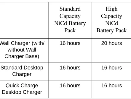
Charging your Battery for the FIRST time
New batteries are supplied in a totally uncharged
state. To ensure maximum battery performance, a new
battery MUST be FULLY charged. Refer to the
fol-lowing table for guidelines.
Table 1: Length of time required to fully charge a new battery
Standard
Capacity
NiCd Battery
Pack
High
Capacity
NiCd
Battery Pack
Wall Charger (with/ without Wall Charger Base)
16 hours 20 hours
Standard Desktop Charger
16 hours 16 hours
Quick Charge Desktop Charger
Getting Started
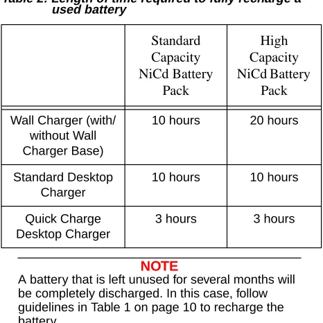
Charging your Battery Subsequently
Refer to the following table
for guidelines on
recharg-ing your batteries.
Table 2: Length of time required to fully recharge a used battery
NOTE
A battery that is left unused for several months will be completely discharged. In this case, follow guidelines in Table 1 on page 10 to recharge the battery.
Charging with Wall Charger
➊Make sure the battery pack is attached to the radio.
NOTE
With the Charger Base, the battery can be charged when connected or not connected to the radio.
➋Turn the radio off (if it is turned on).
Standard
Capacity
NiCd Battery
Pack
High
Capacity
NiCd Battery
Pack
Wall Charger (with/ without Wall Charger Base)
10 hours 20 hours
Standard Desktop Charger
10 hours 10 hours
Quick Charge Desktop Charger
Getting Started
If not using the Charger Base:
➌Lift the dust cover covering the Accessory Connec-tor (16).
➍Insert one end of the Wall Charger into the lower port of the Accessory Connector (16), and the other into an electrical outlet.
If using the Charger Base:
➌Insert the radio / battery into the charging docket.
➍Refer to Table 1 and 2 on pages 10 and 11 for an estimation of the duration involved for charging the battery pack.
➎Unplug the Wall Charger from the radio when charging is complete.
NOTE
The LED on theWall Charger is lit (red) continu-ously during charging.
Charging with Desktop Charger
NOTE
With Desktop Chargers, the battery can be charged when connected or not connected to the radio.
Getting Started
➋Insert the radio / battery into the charging docket.
If using the Quick Charge Desktop Charger:
➊Press the Quick Charge button.
➋Refer to Table 1 and 2 on pages 10 and 11 for an estimation of the duration involved for charging the battery pack.
➌Remove the radio / battery from the charger when charging is complete.
NOTE
The LED on the charger lights up continuously dur-ing chargdur-ing. For the Standard Desktop Charger, it is red for the whole charging period. For the Quick Charge Desktop Charger, it changes from yellow (before charging begins) to red (during charging) to green (when charging is completed).
CAUTION
The Quick Charge Desktop charger runs on a 3-hour timer which begins counting each time you press theQuick Charge button. Removing the bat-tery or radio from the charger before the batbat-tery is fully charged, or removing and replacing battery / radio repeatedly during charging, and then press-ing theQuick Charge button again can overcharge or damage the battery. Press theQuick Charge but-ton only when the battery needs to be fully
Basic Operations
Basic Operations
Turning the Radio On
• Rotate the On / Off and Volume Knob (1) clock-wise to turn the radio on.
Turning the Radio Off
• Rotate the On / Off and Volume Knob (1) anti-clockwise until a click is heard to turn the radio off.
Adjusting the Volume
• Rotate the On / Off and Volume Knob (1) clock-wise to increase your radio’s volume level, or anti-clockwise to decrease it.
NOTE
To do an initial setting of the volume, press and hold theMonitor Button (5) until the background noise is heard. Continue holding theMonitor But-ton (5) while adjusting to the desired volume.
High / Low Power Output
• Press to toggle between high and low power output levels.
NOTE
The indicatorLOW lights up on the LCD Screen (18) when the radio is operating in low power mode.
NOTE
High power mode can improve the clarity of voice activity in areas where signals are weak while low power mode extends battery life.
STEP
C
Basic Operations
Transmitting a Message
➊Select the desired channel or frequency (see “MHz Mode Operations” and “Memory Mode Operations” on pages 25 and 31).
➋Press and hold the Monitor Button (5), and listen for channel activity.
NOTE
If the selected channel is in Carrier squelch mode -CTCSS indicator is not displayed on theLCD Screen (18), you can skip step➋.
➌If the channel is clear, press the Push-To-Talk (PTT) Button (6) and speak clearly into the Micro-phone (11) (see “Information For Safe, Efficient Operation” on page 62 for more information).
NOTE
Unless disabled (“dot” indicator flashes on theLCD Screen (18)), PTT ID tones are heard as they are being transmitted (see“PTT ID” on page 17). You can start your conversation when the tones end.
NOTE
The TX indicator lights up on theLCD Screen (18) when thePush-To-Talk (PTT) Button (6) is pressed.
Basic Operations
IMPORTANT
Whenever you transmit a message, you are using the resources of the transmitting channel. Speaking for long periods of time would deprive others from using that channel.
NOTE
The maximum duration for transmission is deter-mined by the value of theTime-Out-Timer (see “Editing Time Out Timer” on page 53). Once you reach the time limit, a“Time-Out Timer Alert” tone is sounded, and the transmission is cut off.
Receiving a Message
• If the Push-To-Talk (PTT) Button (6) is pressed, release it and listen for incoming messages.
NOTE
Additional Operations
Additional Operations
Display Backlight
• Press the Toggle Light / Enter and Parameter Transfer Button (4) to turn on / off the backlight.
NOTE
To conserve power, the backlight is programmed to automatically turn off after 5 seconds.
NOTE
Pressing either thePush-To-Talk (PTT) Button (6) or theMonitor Button (5) has no effect on the back-light.
PTT ID
If programmed, the radio transmits a DTMF identifica-tion code (unit ID), indicating which portable is in oper-ation.
During a conversation, the code is normally sent only on the initial PTT press (unless PTT ID has been dis-abled). The ‘TX’ indicator lights for the duration of the PTT ID. If there is no PTT or receive activity for 7 sec-onds, or if you change the frequency or channel (or scan resumes), the PTT ID is once again transmitted on the next PTT press.
• Press and hold to enable / disable PTT ID.
NOTE
Additional Operations
Locking / Unlocking the Radio’s Function
Locking the radio will disable all buttons except the Toggle Light / Enter and Parameter Transfer Button (4), Monitor Button (5), Push-To-Talk (PTT) Button (6) and . Pressing a locked button will result being shown on theLCD Screen (18). To lock / unlock the radio:
• Press and hold (for about 2 seconds) until two beeps are heard.
NOTE
Thelock / unlock status remains unchanged even when the power is turned off.
Changing Squelch Modes
Squelch acts as a kind of filtering system which helps to control the amount of signals the radio receives. Configuring the radio to receive only the desired sig-nals minimizes interference from other users of the same channel.
This radio supports Carrier Squelch (CSQ), Coded Squelch - Tone Private-Line (PL), Digital Private-Line (DPL) and Signalling Squelch - Voice Selective Call (SelCall) operations on a per channel basis.
Additional Operations
NOTE
To performSignalling Squelch (SelCall) operation, the radio must be equipped with an optionalDTMF Decode board.
To temporarily override the default receive squelch mode for the channel:
• Press to change between Carrier (CSQ), Coded (PL /DPL) and Signalling (SelCall) squelch modes.
NOTE
The “CTCSS” indicator lights up continuously when the radio is operating inCoded (PL / DPL) mode, flashes when operating inSignalling (SelCall) mode and is not displayed when operating inCarrier (CSQ) mode.
NOTE
When transmitting inSignalling squelch mode, PL / DPL is transmitted (unless it is programmed to ‘000’). After PTT is released, the radio automati-cally enters intoCSQ mode for a period of time. If there is no receive activity, the radio resumes Sig-nalling squelch mode.
NOTE
Whenever you switch from one channel to the other, the default squelch mode of the new channel takes effect.
A SIG
Additional Operations
NOTE
Using this procedure in Memory mode to switch from one squelch mode to the other, does not affect the default squelch mode for the channel. Each time you turn the radio off and on again, or when you switch to another channel and back again, the radio reverts back to its default squelch mode.
Setting Squelch Level
An open (low) squelch level sets the threshold for the receiving signal strength to be low. This means that the radio would receive a great variety of signals, both weak and strong. A tighter (higher) squelch level raises the threshold, thus filtering weak signals and only accepting the stronger ones. To set the squelch level:
➊Press .
➋Rotate the Selector Knob (2) to select the desired squelch level.
➌Press the Toggle Light / Enter and Parameter Transfer Button (4) (or any other button) momen-tarily to adopt the selected squelch level and return to normal operating mode.
IMPORTANT
The radio automatically adopts the new squelch level and returns to normal operation after 5 sec-onds of inactivity.
PL
B
Additional Operations
NOTE
If you reach the upper (‘15’) or lower (‘00’) limit of the squelch range, the squelch level does NOT wrap around to the opposite limit but remains where it is.
Selecting The Receive PL / DPL Squelch Code
NOTE
Receive PL / DPL squelch code selection can only be done in MHz mode.
There are 126 different Receive PL / DPL codes avail-able, numbered from 001 to 126 (see“Receive And Transmit PL / DPL Code Tables” on page 23).
NOTE
Receive PL / DPL code ‘000’ representsCarrier squelch.
➊Press and hold until xxx is shown (where xxx represents the active Receive PL / DPL code number).
➋Rotate the Selector Knob (2) to select the desired active Receive PL / DPL code.
➌Press the Toggle Light / Enter and Parameter Transfer Button (4) (or any other button) momen-tarily to adopt this Receive PL / DPL code and return to normal operating mode.
IMPORTANT
The radio automatically adopts the new Receive PL / DPL code and returns to normal operation after 5 seconds of inactivity.
PL
B
Additional Operations
Selecting A Transmit PL / DPL Squelch Code
There are 126 different Transmit PL / DPL codes avail-able, numbered from 001 to 126 (see“Receive And Transmit PL / DPL Code Tables” on page 23).
NOTE
Transmit PL / DPL code ‘000’ representsCarrier squelch.
➊Press and hold until xxx is shown (where xxx represents the active Receive PL / DPL code number).
➋Press momentarily to toggle the display to xxx (where xxx represents the active Transmit PL / DPL code number).
➌Rotate the Selector Knob (2) to select the desired active Transmit PL / DPL code.
➍Press the Toggle Light / Enter and Parameter Transfer Button (4) (or any other button) momen-tarily to adopt this Transmit PL / DPL code and return to normal operating mode.
IMPORTANT
The radio automatically adopts the newTransmit PL / DPL code and returns to normal operation after 5 seconds of inactivity.
IMPORTANT
If the Receive PL / DPL code is programmed for ‘000’, then the Receive PL / DPL (coded squelch) mode cannot be selected. To select, the Receive code must be changed to any code besides ‘000’ (see“Selecting The Receive PL / DPL Squelch Code” on page 21 and “Selecting A Transmit PL / DPL Squelch Code” on page 22).
PL
B
SQL
PL
B
Receive And Transmit PL / DPL Code Tables
Receive And Transmit PL / DPL Code
Tables
When selecting a Receive or Transmit PL / DPL code (see “Selecting The Receive PL / DPL Squelch Code” on page 21 and “Selecting A Transmit PL / DPL Squelch Code” on page 22), the following tables give the PL frequencies, equivalent PL codes (if appli-cable) and DPL codes corresponding to the display xxx or xxx (where xxx is in the range 001 to 126).
NOTE
and representsCarrier squelch (CSQ) for Receive and Transmit respectively.
rPL.xxx tPL.xxx PL Freq. (Hz) Equiv. PL Code rPL.xxx tPL.xxx PL Freq. (Hz) Equiv. PL Code
000 CSQ − 022 136.5 4Z
001 67.0 XZ 023 141.3 4A 002 69.3 WZ 024 146.2 4B 003 71.9 XA 025 151.4 5Z 004 74.4 WA 026 156.7 5A 005 77.0 XB 027 162.2 5B 006 79.7 WB 028 167.9 6Z 007 82.5 YZ 029 173.8 6A 008 85.4 YA 030 179.9 6B 009 88.5 YB 031 186.2 7Z 010 91.5 ZZ 032 192.8 7A 011 94.8 ZA 033 203.5 M1 012 97.4 ZB 034 206.5 8Z 013 100.0 1Z 035 210.7 M2 014 103.5 1A 036 218.1 M3 015 107.2 1B 037 225.7 M4 016 110.9 2Z 038 229.1 9Z 017 114.8 2A 039 233.6 M5 018 118.8 2B 040 241.8 M6 019 123.0 3Z 041 250.3 M7 020 127.3 3A 042 254.1 −
Receive And Transmit PL / DPL Code Tables
rPL.xxx tPL.xxx EQUIV. DPL CODE rPL.xxx tPL.xxx EQUIV. DPL CODE043 23 085 315
044 25 086 331
045 26 087 343
046 31 088 346
047 32 089 351
048 43 090 364
049 47 091 365
050 51 092 371
051 54 093 411
052 65 094 412
053 71 095 413
054 72 096 423
055 73 097 431
056 74 098 432
MHz Mode Operations
MHz Mode Operations
In the MHz mode the radio displays the selected receive frequency by its MHz designation. You can scroll through all legitimate frequencies from the low-est end to the highlow-est end of the band.
Selecting MHz Mode
If theLCD Screen (18) is displaying a channel number, this means that the radio is currently operating in Memory mode. To operate in MHz mode:
• Press .
Selecting the Frequency Step Size
Frequency step size determines the incremental steps the receiver takes when you rotate theSelector Knob (2), or when the radio is scanning the frequency band.
NOTE
The availablefrequency step sizes are 5, 10, 12.5, 15, 20, and 25 kHz.
IMPORTANT
The selectedfrequency step size is retained even if you turn off the radio.
To select thefrequency step size:
➊Press and hold until the LCD Screen (18) indi-cates the current frequency step size, in this case 12.5 kHz.
MODE
STEP
C
MHz Mode Operations
➋Rotate the Selector Knob (2) to the desired fre-quency step size.
➌Momentarily press Toggle Light / Enter and Param-eter Transfer Button (4) (or any button) to save this frequency step size and return to normal opera-tion.
IMPORTANT
The radio automatically save and return to normal operation after about 5 seconds of inactivity.
NOTE
The user-defined TX frequency may be changed automatically without indication depending on the change in thefrequency step size selected (see “Selecting The TX Offset” on page 28).
Selecting A Receive Frequency
The various ways of selecting a receive frequency are as follows:
(i) Through The Numeric Keypad (19)
In MHz mode:
• Enter the desired frequency
NOTE
MHz Mode Operations
NOTE
If an invalid number is pressed, the valid number nearest to this number is shown. This ensures that selected frequency is within the allowed frequency band. Please also note that valid frequencies are also dependent on thefrequency step size (see “Selecting the Frequency Step Size” on page 25). Only valid numbers are displayed.
(ii) Through The Selector Knob (2)
In MHz mode:
• Rotate the Selector Knob (2) to the desired fre-quency.
(iii) Through Numeric Keypad (19) and Selector Knob (2) combination
In MHz mode:
➊Enter the first few digits of the desired frequency through the Numeric Keypad (19).
➋Press Toggle Light / Enter and Parameter Transfer Button (4) to commit the partially entered fre-quency.
NOTE
Unentered digits are coerced to the nearest valid frequency.
➌Rotate the Selector Knob (2) until the desired fre-quency is displayed.
NOTE
MHz Mode Operations
Selecting The TX Offset
For the AP 73, the transmit frequency can be the same as the receive frequency (no offset), or having a stan-dard positive or negative offset, or it can be a user-defined TX frequency.
➊Press momentarily to toggle between no off-set, standard positive, negative offoff-set, or user-defined TX frequency (refer to the table below).
Programming A User-Defined TX Frequency
➊Press and hold until the “+ –” indicators begin to flash (takes about 3 seconds).
NOTE
TheLCD Screen (18) displays the current user-defined TX frequency.
➋Enter the desired TX frequency via one of the fol-lowing method:
(i) Through The Numeric Keypad (19)
➀Enter the desired TX frequency.
NOTE
To fill in trailing zeros, pressToggle Light / Enter and Parameter Transfer Button (4).
Indicator(s)
Offset Mode
None No offset (simplex)
+ Standard Positive Offset
- Standard Negative Offset
+ - User-defined TX Frequency OFS
MHz Mode Operations
➁Press the Toggle Light / Enter and Parame-ter Transfer Button (4) to accepts the TX fre-quency and return to normal operation.
(ii) Through The Selector Knob (2)
➀Rotate the Selector Knob (2) to the desired user-defined TX frequency.
➁Press the Toggle Light / Enter and Parame-ter Transfer Button (4) to accepts the TX fre-quency and return to normal operation.
(iii) Through Numeric Keypad (19) and Selector Knob (2) combination
In MHz mode:
➀Enter the first few digits of the desired TX fre-quency through the Numeric Keypad (19).
➁Press the Toggle Light / Enter and Parame-ter Transfer Button (4) to commit the partially entered TX frequency.
NOTE
Unentered digits are coerced to the nearest valid frequency.
➂Rotate the Selector Knob (2) until the desired TX frequency is displayed.
NOTE
The frequency increments, or decrements, accord-ing to the selected frequency step size.
MHz Mode Operations
IMPORTANT
The radio automatically exits this mode after 5 sec-onds of inactivity. Partially entered frequency is NOT stored.
NOTE
Memory Mode Operations
Memory Mode Operations
In the Memory mode, the radio operates on the selected memory channel and the LCD Screen (18) displays xxx (where xxx represents the selected channel number). For example, channel 08 is dis-played as follows:
Selecting Memory Mode
If theLCD Screen (18) is displaying a frequency num-ber, this means that the radio is currently operating in MHz mode. To operate in Memory mode:
• Press .
NOTE
If none of the 20 memory channels has been pro-grammed, aninvalid keypress tone sounds and the radio remains in the MHz mode (see “Program-ming A Memory Channel” on page 32).
Selecting A Memory Channel
• Rotate the Selector Knob (2) to the desired chan-nel number.
NOTE
The channel number increments, or decrements, according to the available programmed memory channels. Empty channels are NOT displayed.
Memory Mode Operations
Programming A Memory Channel
There are 20 memory channels available. Each mem-ory channel consists of a receive / transmit frequency pair, the type of TX offset and the offset frequency.
NOTE
Channels 19 and 20 are normally used to store the frequency limits for Programmable Band Scan operation (see“Programmable Band Scan” on page 34).
In MHz mode:
➊Select the desired frequency, type of TX offset and offset frequency (see “MHz Mode Operations” on page 25).
➋Press and hold the Toggle Light / Enter and Parameter Transfer Button (4) until the LCD Screen (18) shows xxx (where xxx is the last channel selected in Memory mode).The The
The channel number flashes if it is unprogrammed, and lights continuously if it is programmed.
➌Use the Selector Knob (2) to select the desired channel number.
Memory Mode Operations
NOTE
The radio remains in MHz mode after successful programming of the channel.
CAUTION
If the selected memory channel was already pro-grammed (channel number lit continuously), the new frequency information overwrites the previous information.
Loading A Memory Channel
The data of a memory channel (receive and transmit frequencies, TX offset type and offset frequency) can be copied over into the MHz mode.
This allows you to tune the radio in the MHz mode from the point specified by the memory channel data.
In Memory mode:
➊Rotate the Selector Knob (2) to the desired mem-ory channel number.
➋Press and hold Toggle Light / Enter and Parame-ter Transfer Button (4) for about 3 seconds.
NOTE
Scan Operations
Scan Operations
Scan operation tells the radio to monitor a number of frequencies or channels. When there are some activi-ties at a particular frequency or channel, the radio stops scanning and changes to that frequency or channel.
Scan modes supported by the radio are:
(i) Programmable Band scan (MHz mode)
(ii) Memory Channel scan (Memory mode)
NOTE
Each frequency or channel is given the same prior-ity i.e.non-priority scan.
IMPORTANT
The radio will not recall the scan state if it is pow-ered off while scanning.
Programmable Band Scan
In the MHz mode, the radio scans over a prepro-grammed range of frequencies usually specified in memory channels 19 and 20.
NOTE
User can specify the frequency range for scanning by programming the frequency limit into memory channel 19 (usually the lower limit) and memory channel 20 (usually the upper limit) (see “Pro-gramming A Memory Channel” on page 32).
Scanning A Frequency Range
Scan Operations
➊Press to begin scanning the preprogrammed frequency range.
NOTE
The frequency range is scanned according to the frequencies specified in channels 19 and 20, and the selected frequency step size. If the operating fre-quency before scanning starts is within the scan range, the radio starts scanning from that fre-quency, otherwise, it starts from the frequency specified by memory channel 19 (or the lowest fre-quency in the band if channel 19 is blank).
NOTE
When the ‘SCAN’ indicator flashes, scanning is in progress and the currently scanned frequency is dis-played.
To change the scan direction:
• Rotate the Selector Knob (2) anti-clockwise.
NOTE
If activity is detected, the radio stops scanning and stays on the active frequency. The ‘SCAN’ indicator remains on, and you will hear the conversation, pro-vided the PL/DPL code (if required) is correct.
IMPORTANT
Radio resumes scanning after approximate 5 seconds (even if activity is still received). If received activity ceases, the radio resumes scan-ning after another 7 seconds, unless receive activ-ity resumes.
➋Press to stop scanning.
N-DEL
D
SCAN
N-DEL
D
Scan Operations
NOTE
PressingPush-To-Talk (PTT) Button (6), a digit on the numeric keypad, or also ends the scanning.
NOTE
The ‘SCAN’ indicator turns off when scanning is terminated and the radio displays the frequency where scanning stopped.
IMPORTANT
If both memory channels are left blank (unpro-grammed), the radio scans the entire frequency band. If channel 19 is programmed but channel 20 is blank, the upper frequency limit becomes the highest frequency in the band. If channel 20 is pro-grammed but channel 19 is blank, the lower fre-quency limit becomes the lowest frefre-quency in the band. If the frequency stored in channel 19 is lower than that stored in channel 20, then scan proceeds in an incrementing order otherwise, scan proceeds in a decrementing order.
Transmitting During Band Scanning
When the scan is locked at a frequency:
• Press Push-To-Talk (PTT) Button (6).
IMPORTANT
Scan Operations
Memory Channel Scan
In the Memory mode, the radio scans allprogrammed memory channels that are also in the channel scan list.
NOTE
The scan list is edited using the Special Program-ming mode (see“Special Programming Mode (SPM)” on page 46).
NOTE
Channels may be temporarily removed from the scan list using a Nuisance Channel Delete feature (see“Nuisance Channel Delete” on page 38).
Scanning Memory Channels
In Memory mode,
➊Press to begin channel scanning.
NOTE
When the ‘SCAN’ indicator flashes, scanning is in progress and theHome Channel (the active channel
before was pressed) is displayed until activity is received on another channel.
The channels are scanned in an increasing order (from lowest to highest). To scan in a decreasing order:
• Rotate the Selector Knob (2) anti-clockwise.
N-DEL
D
SCAN
N-DEL
D
Scan Operations
NOTE
The radio scans through all channels in the prepro-grammed scan list. If activity is detected, the radio stops scanning and stays on the active channel. The ‘SCAN’ indicator remains on, and you will hear the conversation, provided the PL/DPL code (if required) is correct. In Carrier squelch and Coded squelch modes, when activity is over and a 7-sec-ond “hang time” has expired, the display reverts to theHome Channel and scanning resumes.
To stop scanning:
• Press .
Transmitting During Channel Scanning
When the scan is locked at a channel:
• Press Push-To-Talk (PTT) Button (6) to talk, release to listen.
IMPORTANT
The radio transmits on the current active TX fre-quency. But, ifPush-To-Talk (PTT) Button (6) is pressed before the scan is locked at any channel, theHome Channel TX frequency is used.
Nuisance Channel Delete
When the radio is scanning, it would stop at any chan-nel within the scan list that has activity. A chanchan-nel that generates unwanted signals continuously is called a Nuisance Channel. To temporarily remove the chan-nel from the scan list:
• Press and hold for about 3 seconds while scan locks on the Nuisance Channel.
N-DEL
D
SCAN
N-DEL
D
Scan Operations
NOTE
Two medium-pitched “beeps” are sounded indicat-ing the radio has temporary removed theNuisance Channel from its scan list.
IMPORTANT
DTMF Telephone Interconnect
DTMF Telephone Interconnect
Dual Tone Multiple Frequency (DTMF) tones are encoded by the radio to dial into (access) the landline telephone network and return (deaccess) to conven-tional radio operation.
Once the telephone network has been accessed, phone numbers can be dialled either manually or from memory. The keypad provides support for DTMF digits 0 to 9, and the characters A, B, C, D,∗ and #.
NOTE
The radio is capable of storing a maximum of 9 pre-programmed phone numbers (up to 12 digits each).
Placing a Telephone Call
To place a call:
➊Press and hold the Push-To-Talk (PTT) Button (6).
➋Dial the access code manually using the DTMF keys or press then to send the prepro-grammed access code.
➌Release the Push-To-Talk (PTT) Button (6) and wait for a dial tone.
➍Press and hold the Push-To-Talk (PTT) Button (6) and either manually dial the telephone number or press and the phone number location that stores the preprogrammed telephone number.
➎Press the Push-To-Talk (PTT) Button (6) to talk; release to listen.
NOTE
If you press a phone number location which has not been programmed, the radio will sound an Invalid Button Press tone and no further action is taken.
MEM
DTMF Telephone Interconnect
To hang up:
➊Press and hold the Push-To-Talk (PTT) Button (6).
➋Manually dial the deaccess code or press then to send the preprogrammed deaccess code.
Last Number Redial
Manually dialled phone numbers (up to 16 digits long) are stored in numeric location ‘0’ for quick redial capa-bilities.They are sent exactly as preprogrammed tele-phone numbers are. After you receive a dial tone:
• Press and hold Push-To-Talk (PTT) Button (6), then press and .
NOTE
Last Number Redial only stores manually dialled numbers and NOT preprogrammed telephone num-bers. The number set is stored in phone location 0 until the radio is turned off or until another DTMF sequence is manually dialled.
NOTE
If you attempt to perform a last number redial where no manual numbers have yet been dialled since radio power-up, the radio will sound anInvalid But-ton Press But-tone.
Storing a Phone Number
A maximum of 9 telephone numbers (up to 12 digits each) can be stored into the radio memory. Each phone number is stored and recalled via a unique number on the keypad in the range of 1 to 9. The fol-lowing procedure can also be used to store the access / deaccess codes (up to 8 digits each):
MEM
DTMF Telephone Interconnect
➊Press and hold until you hear a second Valid Button Press tone (takes about 2 seconds).
➋Enter a phone number location (in the range of 1 to 9) to store a phone number or press to store the access code or to store the deacess code.
➌Enter the phone number (up to 12 digits long), or access / deaccess code (up to 8 digits long).
NOTE
Valid digits are DTMF digits 0 to 9, the characters A, B, C, D,∗ and #, and pause digits.
NOTE
Pause digit ( )causes the radio to wait in between transmission of the digits programmed before and after it. One or more pause digits can be entered between successive digits of the phone number (or access / deaccess code). When a pause digit is successfully entered, two beeps are heard; the display changes from ‘A’ to ‘-’. Pause digits placed at the end of a phone number are not remembered by the radio.
NOTE
If you make a mistake, press to scroll the cur-sor to the left and erase the incorrect entry. To view a numeric sequence of more than 6 digits, press
or to scroll the cursor to the left or right. MEM
(flashing cursor)
MODE
DTMF Telephone Interconnect
NOTE
All undefined digits are represented by underscores on theLCD Screen (18). A flashing ‘_’ indicates the position for the next number entry. If you reach the maximum number of entries, the cursor position is under the last digit. AnInvalid Button Press tone will sound if you attempt to enter more than the maximum number of digits.
➍Press the Toggle Light / Enter and Parameter Transfer Button (4) to store the phone number (or access / deaccess code) into the designated loca-tion and return to normal operaloca-tion.
Displaying a Stored Phone Number
➊Press momentarily in the receive mode. A Valid Button Press tone is heard.
➋Enter a one-digit phone number location (in the range of 1 to 9) to view the stored phone number or press to view the access code or to view the deaccess code or to review the last num-ber dialled.
NOTE
If the keypad entry is valid, theLCD Screen (18) displays the first 6 digits of the stored phone num-ber or code. For numnum-ber sequences more than 6 digits, after 2 seconds the number begins auto-scrolling to the left in 1 second increments until the last digit is displayed. If the selected phone location is empty, an Invalid Button Press tone is heard.
Voice Selective Call (Optional)
Voice Selective Call (Optional)
To support Voice Selective Call (SelCall) operation, the radio must be equipped with an optional DTMF Decode board.
NOTE
For more information about the availability of this option, contact your dealer.
If your radio is equipped with the Voice Selective Call option, your radio can be called individually by another user, or as part of a small group.
Receiving a Voice Selective Call
When the radio decodes a Voice Selective Call, the LCD Screen (18) indicates the type of SelCall mes-sage being received:
NOTE
The radio will give an alert tone when it success-fully decodes a Voice Selective Call. If either Selec-tive Call Tone Status or Alert Tone Volume is set to ‘OFF’ (see page 53 and 55 ), no tone is heard.
For an Individual Call, the radio automatically trans-mits anAcknowledgement message back to the call-ing radio, if an Acknowledgement ID has been
Individual Call
Group Call
Voice Selective Call (Optional)
programmed (see “Edit Selective Call IDs” on page 52).
When the radio decodes a Voice Selective Call, it enters the carrier squelch mode for a period of time. If there is no receive activity, the radio resumes the selected squelch mode and the LCD Screen (18) reverts to the appropriate receive mode display.
IMPORTANT
If theSelector Knob (2) is rotated or any buttons pressed while theSelCall signal is in progress, the SelCall message disappears and the Selective Call is lost.
Sending a Voice Selective Call
➊Press and hold the Push-To-Talk (PTT) Button (6).
➋Dial the required Selective Call ID.
➌Release the Push-To-Talk (PTT) Button (6).
NOTE
Special Programming Mode (SPM)
Special Programming Mode (SPM)
The Special Programming mode (SPM) allows you to edit all user-modifiable parameters within your radio, such as theChannel Scan list, Phone Access / Deac-cess codes, and Alert Tone Settings. Certain parame-ters (such as theSelective Call Tone Status) are only accessible with the installation of an option board. Upon entry to the Special Programming mode, the radio initiates theSPM Browse menu which provides you with a menu of available parameters and their cur-rent settings.
Entering SPM
➊Turn the radio off (if it is on).
➋Turn the radio on while holding . Keep holding this button until a SPM start-up tone sounds.
NOTE
At power-up, all display segments light up for about 2 seconds. If successful, theLCD Screen (18)
dis-plays .
NOTE
If the battery level is low, the display indicates and the ‘BATT’ indicator flashes. The radio also sounds aLow Battery alert tone. Turn off the radio and replace or recharge the battery.
Exiting SPM
Special Programming Mode (SPM)
SPM Browse Menu
(Clockwise Rotation) (Anti-Clockwise Rotation)
“Beep”
†xxx represents , , ,..., .
Edit Time Out Timer xxx†
Edit Phone Deaccess Code
§
Only displays with option board configured.
Set Battery Saver Status Set Battery Type Set Accessory Option
Edit Phone Access Code Edit Channel Scan List
FIRST ITEM
Erase Single Channel
Edit PTT ID
§Set SelCall Tone Status
§Edit Acknowledment ID
§Edit Individual Call ID
§
Edit Group Call ID
§
Edit All Call ID Alert Tone Volume
Special Programming Mode (SPM)
Editing SPM Parameters
Editing the Channel Scan List
➊In SPM, rotate the Selector Knob (2) to select the Edit Channel Scan List ( ) menu item.
➋Use or to scroll through the channels (01 to 20).
NOTE
The channel scan list does not wrap around to the opposite end of the list. Instead, anInvalid Button Press tone sounds when you have reached the upper or lower limit of the list.
NOTE
A flashing channel number indicates that the chan-nel is excluded from the scan list.
➌Press the Toggle Light / Enter and Parameter Transfer Button (4) to toggle the status of a channel i.e. being included or excluded from the scan list.
NOTE
AValid Button Press tone sounds when the new setting is stored.
➍To exit this menu, select another menu item by turning the Selector Knob (2).
Erase a Single Channel from Memory
➊In SPM, rotate the Selector Knob (2) to the Erase Single Channel ( ) menu.
➋Use or to scroll through the channels (01 to 20).
OFS MEM
Special Programming Mode (SPM)
NOTE
A flashing channel number indicates that the chan-nel is unprogrammed (erased).
➌Press Toggle Light / Enter and Parameter Transfer Button (4) to erase a programmed channel (non-flashing channel numbers).
NOTE
Avalid keypress tone sounds when the channel has successfully erased. PressingToggle Light / Enter and Parameter Transfer Button (4) on an unprogrammed channel results in aninvalid key-press tone and the keykey-press is ignored.
➍To exit this menu, select another menu item by turning the Selector Knob (2).
Editing the Phone Access / Deaccess Codes
➊In SPM, rotate the Selector Knob (2) to the Edit Phone Access ( )or Edit Phone Deaccess
( ) menu.
➋Press or to enter the edit mode.
NOTE
TheLCD Screen (18) displays the current access / deaccess code. For a code which exceeds the 6-digit display length, the rightmost 6-digit flashes to indicate that more digits exist on the right.
➌Enter the new access / deaccess code (up to 8 dig-its) using any of the numeric keys, A, B, C, D,* and #.
Special Programming Mode (SPM)
NOTE
TheLCD Screen (18) shows the new digits as they are being entered. When the cursor is flashing under a digit, the maximum number has been entered. Use or to scroll through the exist-ing code and to erase unwanted digits.
NOTE
Pause digit ( )causes the radio to wait in between transmission of the digits programmed before and after it. One or more pause digits can be entered between successive digits of the phone access / deaccess codes. When a pause digit is successfully keyed, two beeps are heard; the dis-play changes from ‘A’ to ‘-’. Pause digits placed at the end of a phone number are not remembered by the radio.
➍Press the Toggle Light / Enter and Parameter Transfer Button (4) to store the new code and return to SPM Browse Menu.
NOTE
AValid Button Press tone sounds when the new setting is stored.
➎To abort data entry, select another menu item by turning the Selector Knob (2) or wait until the edit mode time-out (after 5 seconds of inactivity).
Edit PTT ID
➊In SPM, rotate the Selector Knob (2) to the PTT ID ( ) menu.
➋Press or to enter the edit mode. OFS MEM
MODE
Special Programming Mode (SPM)
NOTE
TheLCD Screen (18) displays the current pro-grammed PTT ID. For an PTT ID which exceeds the 6-digit display length, the rightmost digit flashes to indicate that more digits exist on the right.
➌Enter the new PTT ID (up to 8 digits) using any of the numeric keys, A, B, C, D,* and #.
NOTE
TheLCD Screen (18) shows the new digits as they are being entered. When the cursor is flashing under a digit, the maximum number has been entered. Use or to scroll through the exist-ing PTT ID and to erase unwanted digits.
NOTE
Pause digit ( )causes the radio to wait in between transmission of the digits programmed before and after it. One or more pause digits can be entered between successive digits of the phone access / deaccess codes. When a pause digit is successfully keyed, two beeps are heard; the dis-play changes from ‘A’ to ‘-’. Pause digits placed at the end of a phone number are not remembered by the radio.
➍Press the Toggle Light / Enter and Parameter Transfer Button (4) to store the new PTT ID and return to SPM Browse Menu.
NOTE
AValid Button Press tone sounds when the new setting is stored.
➎To abort data entry, select another menu item by turning the Selector Knob (2) or wait until the edit mode time-out (after 5 seconds of inactivity).
Special Programming Mode (SPM)
Edit Selective Call IDs
NOTE
The radio must be equipped with a option DTMF Decode board to support theSelective Call Opera-tion.
➊In SPM, rotate the Selector Knob (2) to the Acknowledgment ID ( ) orIndividual Call ID ( ) orGroup Call ID ( ) orAll Call ID ( ) menu.
➋Press or to enter the edit mode.
NOTE
TheLCD Screen (18) displays the current pro-grammed ID number. For an ID which exceeds the 6-digit display length, the rightmost digit flashes to indicate that more digits exist on the right.
➌Enter the new number (up to 8 digits) using any of the numeric keys, A, B, C, D,* and #.
NOTE
TheLCD Screen (18) shows the new digits as they are being entered. When the cursor is flashing under a digit, the maximum number has been entered. Use or to scroll through the existing ID and to erase unwanted digits.
NOTE
Pause digit CANNOT be entered withSelective Call ID therefore a ‘*’ must not be followed immediately by a ‘#’.
➍Press the Toggle Light / Enter and Parameter Transfer Button (4) to store the new ID and return to SPM Browse Menu.
OFS MEM
Special Programming Mode (SPM)
NOTE
AValid Button Press tone sounds when the new setting is stored.
➎To abort data entry, select another menu item by turning the Selector Knob (2) or wait until the edit mode time-out (after 5 seconds of inactivity).
Editing Time Out Timer
➊In SPM, rotate the Selector Knob (2) to the Edit Time Out Timer ( xxx) menu.
NOTE
xxx represents one of , , , ..., . The default display of shows the time-out timer setting of one minute. If the display shows , this indicates that the time-out timer is disabled. This means that there is no limit on the transmit time.
➋Use or to change the current status.
CAUTION
The new setting is stored immediately.
➌To exit this menu, select another menu item by turning the Selector Knob (2).
Setting the Selective Call Tone Status
NOTE
The radio must be equipped with a DTMF Decode board top support theSelective Call Tone Status operation.
Special Programming Mode (SPM)
Selective Call alert tones give an audible indication of receipt of aVoice Selective Call (SelCall). If disabled, the alert tones do not sound whenVoice Selective Call messages are received by the radio.
NOTE
Setting the Alert Tone Volume to off disables all tones regardless of the setting of this parameter (see“Setting the Alert Tone Volume” on page 55).
➊In SPM, rotate the Selector Knob (2) to the Set SelCall Tone Status ( or ) menu.
➋Use or to toggle between On and Off.
CAUTION
The new setting is stored immediately.
➌To exit this menu, select another menu item by turning the Selector Knob (2).
Setting the Sidetones Status
If transmit sidetones is disabled, DTMF sidetones such as phone number and PTT ID sidetones are not heard during transmission.
➊In SPM, rotate the Selector Knob (2) to the Set Sidetones Status ( or ) menu.
➋Use or to toggle between On and Off.
CAUTION
The new setting is stored immediately.
➌To exit this menu, select another menu item by turning the Selector Knob (2).
OFS MEM