DESIGN STRATEGIES FOR POLYMER SOLAR CELLS OF HIGH EFFICIENCY AND LOW COST: MATERIALS, INTERFACE, AND DEVICE
STRUCTURES
Liqiang Yang
A dissertation submitted to the faculty of the University of North Carolina at Chapel Hill in partial fulfillment of the requirements for the degree of Doctor of Philosophy in the Curriculum in Applied Sciences and Engineering.
Chapel Hill 2012 Approved by: James Cahoon John Papanikolas Edward Samulski Sergei Sheiko Wei You
© 2012 Liqiang Yang ALL RIGHTS RESERVED
ABSTRACT
LIQIANG YANG: Design Strategies for Polymer Solar Cells of High Efficiency and Low Cost: Materials, Interface, and Device Structures
(Under the direction of Wei You)
Polymer-based solar cells are very promising candidates towards cheap solar energy, since they can be solution processed and light weight. The best polymer solar cells currently achieve an efficiency of about 8%, which is not competitive with their thin film inorganic counterparts yet. On the other hand, reducing the manufacturing cost and improving the stability of polymer solar cells are also curial for future commercialization of polymer solar cells. These further developments can be facilitated on more detailed design strategies that can only be established through the elucidation of the fundamentals on conjugate polymers, interface, and device structures.
In this thesis, quantitatively investigations of side chains and substituents to construct ideal conjugated polymers for organic solar cells have been presented. The side chain of a conjugated polymer significantly impacts the photovoltaic properties of the corresponding bulk heterojunction (BHJ) solar cell. In addition to side chains, substituents can further tune energy levels, band gaps, and even morphology. A proper combination of side chains and fluorine substituents on the conjugated backbone is a viable approach to high efficient BHJ devices. Moreover, the poly(3-methylthiophene) (P3MT) interfacial layer successfully serves as the hole transport layer for
solution-processed BHJ polymer solar cells with efficiency as high as 5%, which largely extends the lifetime of polymer solar cells. In addition, solution-processed flexible polymer BHJ solar cells based on silver nanowires (Ag NWs) have been successfully fabricated with recoverable efficiency of 2.5%, which indicates that Ag NW electrodes can serve as a low cost, flexible alternative to indium tin oxide (ITO), and thereby improve the economic viability of polymer solar cells. Finally, a conceptually new approach, parallel bulk heterojunction (PBHJ) has been demonstrated in this thesis. The PBHJ solar cell maintains the low cost manufacturing of single junction BHJ cells, while inherits the major benefit of incorporating multiple polymers in tandem cells. Very respectable power conversion efficiency (PCE) over 7% has been obtained in the PBHJ device, which is among the best performances for polymer solar cells.
To my parents,
ACKNOWLEDGEMENTS
First and foremost, I would like to thanks my advisor, Dr. Wei You, for his guidance and patience during my time as a graduate student. He offered countless suggestions for my experiments, presentations, and manuscripts since I began my research in early 2009, and provided me a free atmosphere to develop intellectually on my own. I also would like to thank my committee members, Prof. Cahoon, Prof. Lopez, Prof. Meyer, Prof. Papanikolas, Prof. Samulski, and Prof. Sheiko, for their support and assistance.
Second, I am grateful to have worked with Huaxing Zhou, a former graduate student in Dr. You’s group. He synthesized tons (both in number and quantity!) of new polymers to support my research. Most work of this thesis has been published as a joint effort between us. I also would like to thank the other people who offered contributions, help, and suggestions to make this work possible. Many thanks go to Andrew Stuart for teaching me the fabrication when I joined in lab. I also thank Dr. Jeremy Niskala for his help on evaporator maintenance, Dr. Samuel Price, Rycel Uy, and Wentao Li for their support on new materials, Dr Liang Yan for our fruitful conversations, and all present members, Travis LaJoie, Robert Bruce, Josh Yablonski, and Adam Alman, in Caudill lab for their work on lab cleanup and instrument maintenance.
Finally, special thanks to my family. Without the never-ending support and understanding from my wife Qian Wang and my parents, I would never be able to complete my PhD career.
TABLE OF CONTENTS
LIST OF TABLES……….….xi
LIST OF FIGURES……….…..xii
LIST OF SYMBOLS AND ABBREVIATIONS ……….………....…...xvii
Chapter 1. INTRODUCTION………...……….………1
1.1. Why Polymer Solar Cells………..………...………..1
1.2. Bulk Heterojunction Polymer Solar Cells ………...…….….2
1.2.1. Device Configuration and Mechanism…………...…………...2
1.2.2. Important Parameters of Organic Solar Cells……….….4
1.3. Conjugated Polymers for Polymer Solar Cells …………...……….5
1.3.1. Development of Conjugated Backbone…………...……….6
1.3.2. Side Chains Are NOT Trivial…………...………..….7
1.3.3. Importance of Substituent…………...……….10
1.4. Hole Transport Layers (HTL) in BHJ Polymer Solar Cells ………..13
1.5. Transparent Conductive Electrode for BHJ Polymer Solar Cells ………….14
1.6. Tandem and Multi-blend Solar Cells ………..……..16
1.7. Challenges and Objectives …...…….18
2. QUANTITATIVELY ANALYZING THE INFLUENCE OF SIDE CHAINS OF CONJUGATED DONOR POLYMERS ON THE PERFORMANCE OF PHOTOVOLTAIC BLENDS ………...…….21
2.2. Experimental Section ………23
2.3. Optical and Electrochemical Properties of Polymers………...……..24
2.4. Measured and Calculated Photovoltaic Properties of All Devices …………26
2.5. NDT with 2-hexyldecyl and DTBT with Various Alkyl Chains ………...30
2.6. NDT with Octyl and DTBT with Different Alkyl Chains………..…35
2.7. DTBT With 2-ethylhexyl and NDT with Different Alkyl Chains ………....39
2.8. Conclusion ………...……….42
3. DISENTANGLING THE IMPACT OF SIDE CHAINS AND FLUORINE SUBSTITUENTS OF CONJUGATED DONOR POLYMERS ON THE PERFORMANCE OF PHOTOVOLTAIC BLENDS...…....44
3.1. Introduction………...………44
3.2. Experimental Section ………...…………..….47
3.2.1. Grazing-Incidence Wide-Angle X-ray Scattering (GI-WAXS)…………47
3.2.2. Polymer Solar Cell Fabrication and Testing ……….47
3.3. Optical and Electrochemical Properties……...………..….48
3.4. Morphology of Polymer:PC61BM Thin Films ………...50
3.5. Photovoltaic Properties of BHJ Devices Processed with o-Dichlorobenzene (DCB)………...………..55
3.5.1. Open Circuit Voltage (Voc) ………....57
3.5.2. Short Circuit Current Density (Jsc) ……….……..59
3.5.3. Charge Separation Probability………...62
3.6. Photovoltaic Properties of BHJ Devices Processed with Chlorobenzene (CB)………… …………..………...….67
3.7. Conclusion ………...……….70 4. POLY(3-METHYLTHIOPHENE) AS A HOLE TRANSPORT
LAYER FOR HIGH PERFORMANCE POLYMER SOLAR CELLS…...………72
4.1. Introduction………...………72
4.2. Experimental Section ………74
4.2.1. Fabrication of Interfacial Modifiers……….…………..74
4.2.2. Polymer Solar Cell Fabrication and Testing……….………….……75
4.3. Properties of P3MT Interfacial Layer………...………76
4.4. Photovoltaic Properties of Devices Based on Doped P3MT Layer ……..…77
4.5. Effect of P3MT Thickness on the Performance of Devices...…..80
4.6. Stability and Re-usability of P3MT Interfacial Layer ………..……….82
4.7. Conclusion………...………..….83
5. SOLUTION PROCESSED FLEXIBLE POLYMER SOLAR CELLS WITH SILVER NANOWIRE ELECTRODES...85
5.1. Introduction………...………..85
5.2. Experimental Section ………...………...…88
5.2.1. Synthesis of Silver Nanowires.………..…88
5.2.2. Fabrication of Silver Nanowires Films.……….………89
5.2.3. Polymer Solar Cell Fabrication and Testing...……….…………..90
5.3. Properties of Silver Nanowire Films.……….91
5.4. Performance of BHJ Solar Cells Based on Silver Nanowires.……...………95
5.5. Photovoltaic Properties of Flexible BHJ Solar Cells ………...……...…..104
5.6. Conclusion………...………..108
6. PARALLEL BULK HETEROJUNCTION POLYMER SOLAR CELLS………...110
6.1. Introduction...101
6.3. Experimental Section...114
6.4. Proof of PBHJ Concept …………...………115
6.5. Photovoltaic Properties of PBHJ Solar Cells...119
6.6. Conclusion………...……….…122
7. CONCLUSION AND FUTURE DIRECTIONS……...………124
7.1. Importance of this Thesis ………...………..124
7.1.1. “Trivial” Things Are Non-Trivial………..…..124
7.1.2. Engineer Interface ……….……..125
7.1.3. Design of Device Structure Is Crucial………...126
7.2. Looking Forward...…127
7.2.1. Is a Higher PCE Possible?………...127
7.2.2. How to Further Reduce the Cost?………..……….….130
APPENDICES………...………133
LIST OF TABLES
1.1 Best performing polymers for BHJ solar cells…..……….7
2.1 Calculated and measured electrochemical data of all polymers.……….……26
2.2 Measured and calculated performance parameters for all devices....…..…….28
2.3 Photovoltaic performances of all polymer-based devices..…….……….29
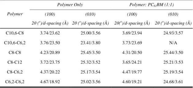
2.4 Diffraction angles and related d-spacing obtained from XRD spectra...33
3.1 Key polymer properties of four polymers.………...…………50
3.2 Representative GIWAXS results of four polymer/PC61BM blends…...……55
3.3 Photovoltaic performances of optimized devices processed in dichlorobenzene ……….…………...…..56
3.4 Calculated photovoltaic performances of four polymers in their BHJ devices ………...………...………..58
3.5 Photovoltaic performances of optimized devices processed in chlorobenzene………..68
4.1 Photovoltaic properties of devices based on undoped P3MT/ITO.………….79
4.2 Photovoltaic properties of devices based on doped P3MT/ITO, PEDOT:PSS/ITO, and bare ITO.…...….81
5.1 Fabrication parameters and photovoltaic performances of devices...….101
5.2 Work function of anode electrodes ………...….104
5.3 Photovoltaic performances of flexible devices under bending condition.….108 6.1 Photovoltaic performances of devices with optimized thickness.………….122
LIST OF FIGURES
1.1 A typical structure of “layer-by-layer” polymer solar cell ………...3 1.2 Schematic illustration of the active layer in BHJ polymer solar cell……….…4 1.3 A preventative current density-voltage (J-V) curve and key
parameters of device measurement……….………...5 1.4 Illustration of a typical conjugated polymer for the application
in organic solar cells.……… ………....6 1.5 Chemical structures of PBDT-DTBT, PBDT-4DTBT,
PBDT-3DTBT and PBDT-DTsolBT………....….9 1.6 Energy diagram electrodes and semiconductors used in ternary
blends. Curved arrows indicate allowed charge transfer reactions
in the multi-blend system………...………..17 1.7 Schematic structure of polymer tandem cells.……….18 2.1 The chemical structures of the six polymers based on the
PNDT-DTBT backbone ……….……….23 2.2 Normalized absorption spectra of polymer solutions in
trichlorobenzene at a) 140 ºC and b) room temperature..………....24 2.3 Cyclic voltammograms of the oxidation and reduction
behavior of thin films .……….………...…….25 2.4 Schematic nanomorphology of active layer in BHJ devices...31 2.5 AFM phase images of C10,6-C8:PC61BM film (left) and
C10,6-C6,2:PC61BM film (right)...32
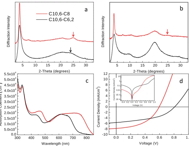
2.6 a) XRD spectra of the C10,6-C8 and C10,6-C6,2 polymers in thin films (arrows indicating (010) peaks). b) XRD spectra of C10,6-C8:PC61BM (1:1) and C10,6-C6,2:PC61BM (1:1) blends
in thin films (arrows indicating (010) peaks). c) Absorption spectra of C10,6-C8:PC61BM (1:1) and C10,6-C6,2:PC61BM
(1:1) blends in thin films. d) Current density vs. voltage characteristics in the dark (inset) and illumination under 1 sun, AM1.5 conditions for C10,6-C8 and C10,6-C6,2 polymer based
BHJ solar cells...35 2.7 a) XRD spectra of the C8-C8, C8-C12, and C8-C6,2 polymers
in thin films (arrows indicating (010) peaks). b) XRD spectra of C8-C8:PC61BM (1:1), C8-C12:PC61BM (1:1), and C8-C6,2:
PC61BM (1:1) blends in thin films (arrows indicating (010)
peaks). c) Absorption spectra of C8-C8: PC61BM (1:1), C8-C12:
PC61BM (1:1), and C8-C6,2:PC61BM (1:1) blends in thin films.
d) Current density vs. voltage characteristics in the dark (inset) and illumination under 1 sun, AM1.5 conditions for C8-C8,
C8-C12, and C8-C6,2 polymers based BHJ solar cells...37 2.8 AFM images of C8-C8:PC61BM film in a 1:1 ratio blend.
(left: height image; right: phase image)...38 2.9 a) XRD spectra of the C10,6-C6,2, C8-C6,2, and C6,2-C6,2
polymers in thin films (arrows indicating (010) peaks). b) XRD spectra of C10,6-C6,2:PC61BM (1:1), C8-C6,2:
PC61BM (1:1), and C6,2-C6,2:PC61BM (1:1) blends in thin
films (arrows indicating (010) peaks). c) Absorption spectra of C10,6-C6,2:PC61BM (1:1), C8-C6,2:PC61BM (1:1), and
C6,2-C6,2:PC61BM (1:1) blends in thin films. d) Current
density vs. voltage characteristics in the dark (inset) and illumination under 1 sun, AM1.5 conditions for C10,6-C6,2,
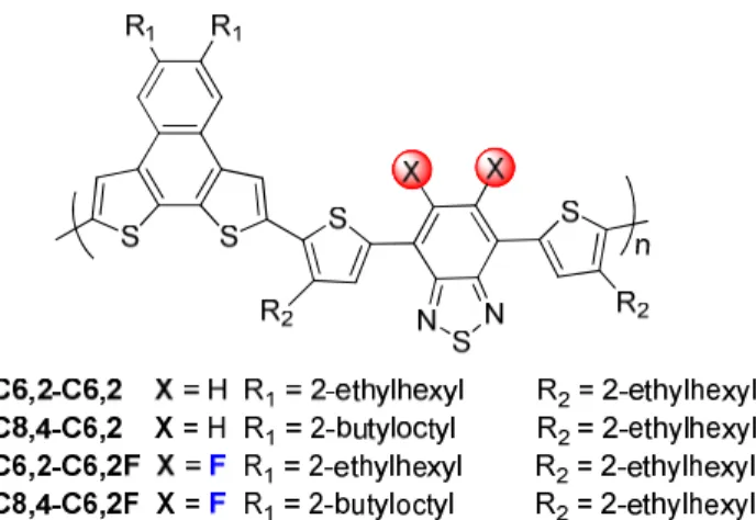
C8-C6,2, and C6,2-C6,2 polymers based BHJ solar cells……...41 3.1 The chemical structures of four polymers based on
the PNDT-DTBT backbone.………...……….46 3.2 Normalized absorption spectra of four polymers in
dichlorobenzene at a) 140 ºC and b) room temperature.………..…49 3.3 AFM phase images (2 × 2 µm) of a) C6,2-C6,2, b) C8,4-C6,2,
c) C6,2-C6,2F and d) C8,4-C6,2F-based BHJ devices processed
with dichlorobenzene………...51 3.4 GI-WAXS data of a) C6,2-C6,2, (b) C8,4-C6,2, (c) C6,2-C6,2F
and d) C8,4-C6,2F-based polymer:PC61BM BHJ films processed
with dichlorobenzene. e) The corresponding sector averages in plane (qy) and out of plane (qz) along with f) a zoom-in comparison
of the (010) peaks.………..…..53 3.5 a) Light current density vs. voltage characteristics of
optimized BHJ solar cells processed in dichlorobenzene under 1 Sun condition (100 mW/cm2). b) Absorption
coefficient of polymer/PC61BM thin films processed in dichlorobenzene..…55
layer thickness for each polymer blend processed from DCB………...……61 3.7 a) Photo current density vs. effective voltage and b)
charge separation probability vs. applied voltage curves of optimized BHJ solar cells processed in dichlorobenzene
under 1 Sun condition (100 mW/cm2)………..………...…62 3.8 a) Current density vs. voltage characteristics of optimized
BHJ solar cells processed in chlorobenzene under 1 Sun condition (100 mW/cm2). b) Absorption coefficient of
polymer/PC61BM thin films spun coated with chlorobenzene.………...67
3.9 The GI-WAXS sector averages of C8,4-C6,2-based
polymer:PC61BM BHJ films processed with different solvent………69
3.10 AFM height images of a) C6,2-C6,2, b) C8,4-C6,2, c) C6,2-C6,2F and d) C8,4-C6,2F based BHJ devices
processed with chlorobenzene.………….………..…….70 4.1 The device structure of the BHJ polymer solar cell based
P3MT interfacial layer. The P3MT interfacial layer is covalently bound to ITO surfaces by surface-initiated Kumada
catalyst-transfer polycondensation (SI-KCTP) using surface bound (aryl)Ni(II)-Br Initiators, preventing
delamination during processing of additional layers………...74 4.2 Transmission spectra for a) 40 nm PEDOT:PSS reference
and a series of undoped P3MT layers with different thicknesses,
and b) P3MT layer before and after doping...….………..77 4.3 Characteristic J-V curves of the BHJ solar cell devices based
on a) P3HT and b) PBnDT-DTffBT under one Sun condition
(100 mW/cm2).………...78
4.4 Optical properties of P3HT and PBnDT-DTffBT.……….……..80 4.5 Characteristic J-V curves of the BHJ solar cell devices
based on reused P3MT/ITO substrates under one Sun
condition (100 mW/cm2).………...………….….83 5.1 a) Energy-level diagram showing the highest occupied
molecular orbital (HOMO) and lowest unoccupied molecular orbital (LUMO) energies and work functions of each of the component materials. b) The device structure of the
5.2 SEM images of Ag NW network a) before and b) after PEDOT:PSS coating; AFM images (10 × 10 µm; inset 2 × 2 µm) of the Ag NW network b) before and c) after
PEDOT:PSS coating………...……….92 5.3 a) Transmission spectra for ITO reference, Ag NW films on
glass and on PET; Photographs of highly transparent Ag NW
films transferred onto b) glass and c) PET..………….………93 5.4 Sheet resistance of the pure Ag NW and PEDOT:PSS coated
Ag NW films on PET substrates under different bending conditions. Inset shows the experimental setup of the
two-probe electrical measurement. Direct contact of alligator clips to copper tape electrodes on Ag NW films was used
in order to ensure good electrical contact during bending....………...94 5.5 Chemical structures of P3HT, PBnDT-FTAZ, and PBnDT-DTffBT...…...96 5.6 Cross-sectional SEM images of Ag NW-based devices made
5.7 with a) P3HT, b) PBnDT-FTAZ, and c) PBnDT-DTffBT;
d) ITO-based reference device based on PBnDT-DTffBT………..98 5.8 Characteristic J-V curves of the BHJ solar cell devices based
on a) P3HT, c) PBnDT-FTAZ, and e) PBnDT-DTffBT under one Sun condition (100 mW/cm2); EQE and absorption of the BHJ solar cell devices based on b) P3HT, d) PBnDT-FTAZ,
and f) PBnDT-DTffBT...….99 5.9 a) The experimental setup used for measuring the J-V curves
of flexible devices. b) Direct contact of alligator clips to copper tape on the Ag NW anode was used in order to ensure
good electrical contact during the bending……….…..….105 5.10 Characteristic J-V curves of flexible devices during bending..……….106 6.1 Schematic structure of different types of polymer tandem cells..…………..112 6.2 Schematic structure and energy diagram of PBHJ devices.………..114 6.3 Chemical structures and band gaps of TAZ, DTBT, DTffBT and DTPyT...116 6.4 Absorption of the PBHJ devices and their sub-cells based
on a) TAZ/DTBT and d) DTffBT/DTPyT; EQE of the PBHJ devices and their sub-cells based on b) TAZ/DTBT and e) DTffBT/DTPyT; Characteristic J-V curves of the PBHJ devices
and their sub-cells based on c) TAZ/DTBT and f) DTffBT/DTPyT……….118 6.5 Characteristic J-V curves of the PBHJ devices and single
BHJ cells with optimum thickness based on a) TAZ/DTBT
and d) DTffBT/DTPyT..………....119 6.6 EQE of the PBHJ devices with different composition of a)
TAZ/DTBT and b) DTffBT/DTPyT; Jsc and Voc of the PBHJ
devices as a function of the amount of c) TAZ in DTBT and
LIST OF SYMBOLS AND ABBREVIATIONS
AFM atomic force microscope (microscopy) Ag NWs silver nanowires BHJ bulk heterojunction BnDT benzo[1,2-b:4,5-b′]dithiophene C10,6 2-hexyldecyl C12 dodecyl C6,2 2-ethylhexyl C8 octyl C8,4 2-butylcotyl CB chlorobenzene CV cyclic voltammetry DCB dichlorobenzene DTBT 4,7-di(thiophen-2-yl)benzothiadiazole DTffBT fluorinated 4,7-di(thiophen-2-yl)benzothiadiazole
Eg difference between HOMO and LUMO of organic semiconductor
EQE external quantum efficiency
F fluorine
FF fill factor
FTAZ fluorinated 2-alkyl-benzo[d][1,2,3]triazoles FWHM full width at half maximum
G exciton generation rate
η power conversion efficiency HOMO highest occupied molecular orbital HTL hole transport layer
IP in-plane
IQE internal quantum efficiency ITO indium tin oxide
Jph photocurrent density
Js reverse saturation current density
Jsat saturated photocurrent density
Jsc Short circuit current density
k Boltzmann constant
LUMO lowest unoccupied molecular orbital Mn number average molecular weight Mw molecular weight
MWNT multiwall-carbon nanotubes n diode ideality factor
NDT naphtho[2,1-b:3,4-b']dithiophene OOP out-of-plane
OPV organic photovoltaic
P charge separation probability P3HT poly(3-hexylthiophene) P3MT poly(3-methylthiophene) PBHJ parallel bulk heterojunction
PC71BM phenyl-C71-butyric acid methyl ester
PC61BM phenyl-C61-butyric acid methyl ester
PCE power conversion efficiency PDI polydispersity index
PEDOT:PSS poly(3,4-ethylenedioxythiophene):poly(styrenesulfonate) PET polyethylene terephthalate
PV photovoltaic
q elementary charge
Rsh shunt resistance
Rs series resistance
SAM self-assembled monolayer SCLC space charge limited current
SEM scanning electron microscope (microscopy) SWNT single-wall carbon nanotube
TAZ 2-alkyl-benzo[d][1,2,3]triazoles TCB trichlorobenzene
TEM transmission electron microscope (microscopy) UPS ultraviolet photoelectron spectroscopy
UV-Vis ultraviolet–visible spectroscopy
V Volt
V0 compensation voltage
Vapp applied voltage
XRD X-ray diffraction
∆EDA difference between HOMO of donor and LUMO of acceptor
CHAPTER 1
INTRODUCTION 1.1. Why Polymer Solar Cells
With the world energy demand increasing, the search for alternative energy sources is a growing academic and industrial pursuit. The limited reserve of carbon-based fuels and increased emissions of greenhouse gases (e.g. CO2) has placed a greater demand on the
renewable and clean energy, such as hydropower, geothermal, wind, and solar. Compared with other renewable energy sources, harvesting energy directly from the Sun via photovoltaic (PV) technologies is increasingly being recognized as one of the most promising long-term solutions – or maybe the ultimate solution – to a sustainable future. Since the 1950s, the power conversion efficiency (PCE) of these devices has steadily improved. Currently, crystalline silicon crystalline silicon based cells and multi-junction solar cells can achieve up to 25%1 and 35% PCE2, respectively. Furthermore, in a multi-junction device, where two or more sub-cells are stacked to absorb different regions of the solar spectrum, PCE over 40% have been achieved.3 However, the high cost of single crystal growth and the complicated manufacturing process compared to fossil fuels limit their wide applications. In order to lower the cost, other types of solar cells such as such as amorphous silicon, cadmium telluride, dye sensitized solar cells, and organic solar cells have been developed. Among them, polymer solar cells are considered promising low-cost alternatives to existing silicon photovoltaics, because of the low weight, the
tenable electronic and optical properties of conjugated polymers and the potential for low-cost roll-to-roll manufacturing.4
1.2. Bulk Heterojunction Polymer Solar Cells
In 1959,the first organic solar cell was made by Kallman et al. based on a single crystal of anthracene5 with a power efficiency of 0.02%. The low efficiency is partly due to organic materials with high dielectric constant, which lead to strongly bound electron-hole pairs, and therefore poor charge separation. In 1986 Tang reported an efficiency of 0.95% and FF of 65% by using thin-film double-layer photovoltaic cells of copper phtalocyanine (CPc) and a perylene tetracarboxylic (PT) derivative6. It was found that excitons can easily be dissociated into electrons and holes at the interface of CPc and the PT layer due to their differences in energy levels. The success of this electron donor/acceptor concept largely stimulated research in the field of organic photovoltaics. The seminal discovery of rapid photoinduced electron transfer from a conjugated polymer to the buckminsterfullerene molecule in 1992,7 led to the first demonstration of an efficient polymer solar cell based on poly[2-methoxy-5-(2’-ethylhexyloxy)-1,4-phenylenevinylene] (MEH-PPV) and a soluble version of the fullerene, [6,6]-phenyl-C61-butyric acid methyl ester (PC61BM) in 1995.8 Since then, the new concept, coined
as “Donor-Acceptor Bulk Heterojunction (BHJ)” solar cell, has remained as one of the most active research fields in the past two decades. 9
1.2.1 Device Configuration and Mechanism
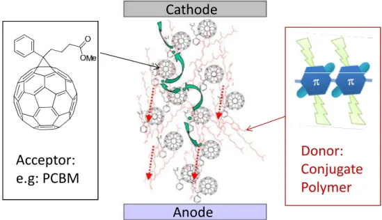
A typical polymer solar cell has a “sandwich” structure (Fig. 1.1) and it is fabricated layer-by-layer, whose four layers, from bottom to top, are the anode, the
poly(3,4-ethylenedioxythiophene) poly(styrenesulfonate) (PEDOT:PSS) layer, the active layer, and the cathode. The anode is usually a plastic or glass substrate coated with a transparent Indium Tin Oxide (ITO) layer. The conductive PEDOT:PSS is used to adjust the energy level and provide a smooth surface to improve the electrical contact between the ITO and the active layer.10 The organic active layer is used for light absorption and charge separation. The cathode is usually made of a low work function metal such as Aluminum or Calcium.
Figure 1.1. A typical structure of “layer-by-layer” polymer solar cell
The fundamental operating principle of a polymer solar cell is based on the cooperative interaction of molecular or polymeric electron donors and acceptors. Typically, photoexcitation of the donor generates excitons (bound electron-hole pairs), as opposed to free charges in the inorganic solar cells, due to the low dielectric constant of organics. These excitons will only find sufficient energetic driving force for dissociation into free charges at the interface with an electron acceptor of suitably high electron affinity. Excitons must therefore diffuse through the donor in order to reach an acceptor site where charges can be generated and then finally be transported through the donor phase (holes) and the acceptor phase (electrons). It is this necessity of having two distinct and interacting species that is the defining characteristic of the organic solar cell. Despite this common attribute, many different types of organic solar cells exist, which can be
Cathode
grouped in two general categories distinguished by the architecture of the active layer, with either a donor-acceptor bilayer or a bicontinuous donor-acceptor composite, known as a bulk-heterojunction (BHJ). In contrast to the double layer structure, the success of the bulk hetreojunction solar cell can be attributed to the interpenetrated network between the donor and acceptor (Fig. 1.2). The interpenetrated network of BHJ offers two advantages: (a) it minimizes the travelling distance of excitons (electron-hole pair generated upon light absorption) to the donor/acceptor (D/A) interface, and concurrently maximizes the D/A interfacial area, thereby ensuring the exciton dissociation at the D/A interface to generate maximum free charge carriers; and (b) it offers charge transport pathways to facilitate the charge collection at electrodes, completing the conversion of the photon energy to electrical energy (i.e., photovoltaic effect).
Figure 1.2. Schematic illustration of the active layer in BHJ polymer solar cell
1.2.2 Important Parameters of Organic Solar Cells
The single most important performance parameter of a solar cell is the power conversion efficiency (PCE or η), which can be defined as the ratio of maximum power
Cathode
Anode
Acceptor:
e.g: PCBM
Donor:
Conjugate
Polymer
out (the blue area shown in Fig. 1.3) to power in. When illuminated with light and placed under short circuit (i.e. applied voltage = 0 V), photocurrent is produced in the external circuit. This point is labeled as the short-circuit current (Jsc) on the standard current
density vs. voltage (J-V) measurement (Fig. 1.3). On the other hand, under open circuit (i.e. J = 0 A/m2), the value of applied voltage is named as the open circuit voltage (Voc).
The fill factor (FF) is defined as the ratio of maximum power divided by Jsc × Voc. Therefore, the PCE is proportional to the product of Jsc, Voc, and FF as shown in the
equation: oc sc in V J FF PCE P × × = .
Figure 1.3. A preventative current density-voltage (J-V) curve and key parameters of device measurement.
1.3. Conjugated Polymers for Polymer Solar Cells
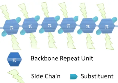
The development of new materials has always been the driving force to reach higher efficiency values, with significant contribution from the careful control of the morphology of the Donor-Acceptor blend. A typical conjugated polymer used as the electron donor in polymer solar cells is illustrated in Fig. 1.4. Generally, a conjugated
C
u
rr
e
n
t
D
e
n
si
ty
(
J)
Short Circuit Current (J
sc)
Open Circuit Voltage (V
oc)
Maximum
Power Out
polymer can be arbitrarily divided into three constituting components: backbone, the side chains and
Figure 1.4. Illustration of a typical conjugated polymer for the application in organic solar cells
3.1.1. Development of Conjugated The conjugated backbone
the polymer solar cell-related physical energy levels, band gap and
have been reported so far
poly(phenylenevinylene) (PPV) based polymers, such as MEH methoxy-5-(3’-7’-dimethyloctyloxy)
of MDMO-PPV based BHJ solar cells reached over 3% employing chlorinated solvents to control the morphology band gap (over 2 eV) of PPV based polymers signifi by BHJ solar cells. A new polymer
narrower band gap (1.9 eV) and thereby higher achievable intensive studies. By the careful control of
polymer can be arbitrarily divided into three constituting components: the conjugated and the substituents.
Illustration of a typical conjugated polymer for the application in organic
onjugated Backbone
The conjugated backbone is the most important component because it dictates most of related physical properties of the conjugated polymer
energy levels, band gap and molecular interactions. Hundreds of different backbones have been reported so far.11-13 For example, early studies had been focused on poly(phenylenevinylene) (PPV) based polymers, such as MEH-PPV and
dimethyloctyloxy)-1,4-phenylenevinylene] (MDMO-PPV
based BHJ solar cells reached over 3% – with a high Voc of 0.82 V
employing chlorinated solvents to control the morphology.14,15 Unfortunately, the large band gap (over 2 eV) of PPV based polymers significantly limited the current achievable
new polymer, regioregular poly(3-hexylthiophene) (P3HT)
) and thereby higher achievable Jsc became the new focus of
intensive studies. By the careful control of the morphology of the Donor
the conjugated
Illustration of a typical conjugated polymer for the application in organic
dictates most of the conjugated polymer, such as Hundreds of different backbones s had been focused on PPV and
poly[2-PPV). The PCE of 0.82 V – by Unfortunately, the large cantly limited the current achievable hexylthiophene) (P3HT), with a became the new focus of Donor-Acceptor
blended thin films via thermal16 or solvent annealing,17 the efficiency of P3HT based BHJ devices was able to reach over 5%.18,19 Recognizing that a smaller band gap polymer can absorb more light with potentially much higher efficiency, the focus of new materials development has been shifted to conjugated polymers of smaller band gaps. The heavy investment in the research of small band gap polymers has paid off quite well: a number of new polymers have shown over 7% PCE in BHJ solar cells (Table 1.1),12,20-28 with over 9% being reported in the press.29
Table 1.1. Best performing polymers for BHJ solar cells
Polymer HOMO (eV) Egap (eV) Voc (V) Jsc (mA/cm2) FF b η (%) Ref. – 5.15 1.6 0.74 14.50 0.69 7.4 (C70) 8.4 (C70) 21 20 – 5.5 1.88 0.88 10.6 0.66 6.1 (C70) 7.2 (C70) 23 24 – 5.60 1.69 0.85 12.6 0.68 7.3 (C70) 25 – 5.57 1.73 0.88 12.2 0.68 7.3 (C70) 26 – 5.56 1.82 0.92 13.1 0.61 7.3 (C70) 27 – 5.54 1.7 0.89 12.8 0.62 7.2 a 30 – 5.36 2.0 0.79 12.45 0.72 7.1 a 28
a. No additives were added. PC61BM was used. b. FF: fill factor
1.3.2 Side Chains Are NOT Trivial
It is well-known that decorating the polymer backbone with side chains can effectively improve the solubility of the polymer, which is a crucial prerequisite toward achieving high molecular weight of the resulting conjugated polymer. However, substituting the small hydrogen atoms on these aromatic units with rather big alkyl or
Si S S S n N O O R2 R1 R1 PBnDT-DTffBT n S S R2 R2 F F N SN S S R1 R1
alkoxy chains often result in significant steric hindrance between these aromatic units on the conjugated backbone. For example, a computational simulation revealed that severe steric hindrance introduced by these alkyl/alkoxy chains on the 4,7-di(thiophen-2-yl)benzothiadiazole (DTBT) lead to a twisted conjugated backbone in polymers incorporating the substituted DTBT.31 Therefore the hole mobilities of the polymers incorporating such substituted DTBT were noticeably lower than that of the polymer with un-substituted DTBT, which accounted for a smaller Jsc in the former case.31 In an earlier
study, the homopolymers of alkylated DTBT were prepared by Jayakannan et al. by varying alkyl chains on either 3 or 4 positions of the thienyl groups.32 Though relatively high molecular weight polymers were obtained, the steric hindrance introduced by these alkyl chains in these polymers led to much larger band gaps than that of the homopolymer of un-substituted DTBT.33 Later, Wang et al. synthesized a series of internal donor-acceptor type of copolymers containing benzothiadiazole (BT) and four thiophenes incorporating side chains on different position.34 Despite indentical alkyl side chains, the positions where these alkyl side chains are attached to different thiophene rings have significant influence on the physical properties and photovoltaic performance of resulting polymers. Positioning these alkyl chains close to the fluorene renders large steric hindrance during polymerization, which results in a significantly lower molecular weight in PFO-M2 and consequently a poor performance of 0.74% compared with 1.82% in PFO-M1 and 2.63% in PFO-M3.
Most recently, You and co-workers systematically investigated what effect the side chain positions had on the optical, electrochemical, and photovoltaic properties of conjugated polymers using PBDT-DTBT as the model polymer (Fig. 1.5).35 Not
surprisingly, attaching alkyl chains greatly improved the solubility of resulting polymers; however, the anchoring positions significantly impacted the photovoltaic properties in BHJ solar cells. As discussed earlier, anchoring solubilizing chains at the inner core of DTBT introduces significant steric hindrance along the conjugated backbone, leading to anincrease in the band gap. Moreover, the electron density of HOMO energy levels of PBDT-3DTBT and PBDT-DTsolBT are essentially localized on the BDT unit, indicating a lack of delocalization. Therefore low efficiencies were observed for both PBDT-3DTBT (0.21 %) and PBDT-DTsolBT (0.01 %). On the other hand, shifting alkyl chains to the 4 positions of the flanking thienyl groups (PBDT-4DTBT) has a minimal impact on the band gap and energy levels when compared with PBDT-DTBT. Due to its increased solubility, PBDT-4DTBT possesses a higher molecular weight (Mn: 27 kg/mol) and shows enhanced intermixing with PC61BM, without the severe aggregation of polymers observed with PBDT-DTBT. Therefore, PBDT-4DTBT based solar cells result in an overall efficiency of 1.83%, which is significantly higher than that of the PBDT-DTBT based devices (0.72 %). These results present a good example of how the positioning side chains does in fact matter.
Figure 1.5. Chemical structures of PBDT-DTBT, PBDT-4DTBT, PBDT-3DTBT and PBDT-DTsolBT.
Even when the side chains are “properly” anchored on the conjugated backbone, the length and shape of these side chains also have a noticeable (sometimes substantial) impact on the properties of resulting conjugated polymers. Gadisa et al. completed a comparative investigation on the photovoltaic properties of BHJ devices based on a series of poly(3-alkylthiophene)s of butyl (P3BT), pentyl (P3PT) and hexyl (P3HT).36 The longer side-chains facilitate the clustering of PC61BM molecules and establish fast
electron-percolation pathways, leading to improved electron mobility. Since holes and electrons exhibit well-balanced mobilities in the case of P3HT: PC61BM, a better fill
factor was observed. In another study, Egbe et al. grafted different side chains to the backbone of a series of anthracene-containing poly(p-phenylene-ethynylene)-alt-poly(p-phenylene-vinylene)s (PPE-PPV) copolymers to tune the π–π stacking ability of the materials.37 An increase of the open circuit voltage from ∼0.65 V to ∼0.90 V was observed with decreasing side chain density. It is because high density side chains dilute the concentration of the absorbing conjugated species per volume unit and reduce the interfacial area between donor polymer and PC61BM leading to strong phase separation
and concomitant poor photovoltaic performance. 1.3.3. Importance of Substituent
Though the energy levels and band gap of a conjugated polymer is mainly determined by the selection of conjugated aromatic units, substituents can be used to further tune energy levels, band gaps, molecular interaction and even morphology.
Using archetypical poly(p-phenylene-vinylene) (PPV) as the model polymer, the substituent effect on conjugated polymers was systematically studied by Bredas and Heeger with the valence effective Hamiltonian (VEH) method.38 Attaching electron
donating methoxy groups to the benzene unit of the PPV would raise the highest occupied molecular orbital (HOMO) energy level when compared with the original PPV (with similar lowest unoccupied molecular orbital (LUMO) level). This effect was also observed experimentally.39 When switching to the electron withdrawing group (such as cyano), stabilization on both HOMO and LUMO levels would be expected. However, calculations found that the band gaps of the cyano PPVs would be larger than that of PPV, because of the asymmetry in the stabilization of the HOMO and LUMO levels by the cyano substituent. Furthermore, the position of the cyano (either on the phenylene or on the vinylene) affects the energy levels and band gap. When cyano was added on the vinylene, the calculated LUMO level was noticeably lower than that of the analog with cyano on the phenylene, with less difference on the HOMO energy levels. The authors attributed this effect to the different number of π electrons on the vinylene and phenylene. Since vinylene unit only has two π electrons whereas phenylene unit has six, substitution on the vinylene would introduce a relatively larger perturbation to the conjugated backbone, further lowering the LUMO level. All these results presented above indicate that electron donating substituents (such as methoxy) would have a more significant impact on the HOMO level, while electron withdrawing ones (such as cyano) would affect more strongly on the LUMO level.
Another interesting substituent is the fluorine. Fluorine is the smallest electron withdrawing group with a van der Waals radius of 1.35 Å and a Paul electronegativity of 4.0. Fluorinated organic molecules exhibit a series of unique features such as great thermal and oxidative stability,40 elevated resistance to degradation,41 enhanced hydrophobicity and high lipophobicity in perfluorinated substances.42 In addition, these
fluorine atoms often have a great influence on inter- and intramolecular interactions via C-F···H, F···S and C-F···πF interactions.41,43 Applying fluorine substitution in the D-A
polymers was investigated by You and co-workers in two recent studies.28,30 In one report, they added two fluorine atoms to the commonly employed benzothiadiazole (BT), converting BT into fluorinated benzothiadiazole (ffBT).30 The ffBT based polymer showed decreased HOMO and LUMO levels but a similar band gap when compared with those of its non-fluorinated analog. Preliminary PV tests on BHJ devices demonstrated both increased Voc (0.91 V) and Jsc (12.9 mA/cm2). Together with an also enhanced fill
factor of 0.61, an impressive PCE of 7.2% was thus obtained without special treatments. In another related study, BnDT based copolymers (PBnDT-FTAZ) with 5,6-difluoro-2H-benzo[d][1,2,3]triazole (FTAZ) as the acceptor unit was synthesized.28 This polymer exhibited a medium band gap of 2.0 eV compared with that of the DTBT based polymer due to the weaker electron affinity of FTAZ. Surprisingly, in spite of a band gap of ~ 2.0 eV, the current of PBnDT-FTAZ could be larger than 12 mA/cm2 (depending upon the thickness of the active layer), which can be explained by its high molecular weight and large hole mobility. The BHJ devices based on PBnDT-FTAZ consistently showed a higher FF and Jsc than those of devices based on the polymers without fluorine
substituents at comparable thicknesses. A peak PCE of 7.1% was obtained in BHJ devices of PBnDT-FTAZ:PC61BM without annealing and any additives. Remarkably,
PBnDT-FTAZ:PC61BM solar cells can still achieve over 6% efficiency even at an
unprecedented thickness of 1 µm (of the active layer), which makes PBnDT-FTAZ an excellent polymer for tandem solar cells.
1.4. Hole Transport Layers (HTL) in BHJ Polymer Solar Cells
The electrical properties at the interfaces are critical for governing solar cell performances, because the contact resistance between the organic photoactive layer and the electrode can strongly impact the charge collection, which is one of the fundamental steps of energy conversion in BHJ solar cells. In addition, anode/cathode interfacial layers are used as charge selective contacts between the BHJ active layer and the electrodes. Typically, a thin layer of PEDOT:PSS is applied in between the ITO and the
active layer to improve the electrical contact between the ITO and the active layer and to adjust energy levels.10 However, a number of drawbacks exist with this approach that limits the application of polymer solar cells: the acidic nature of PEDOT:PSS can corrode the ITO electrode,44,45 leading to a chemical instability at the interface,46 and PEDOT:PSS does not have sufficient electron blocking capability,45 which could render electron leakage at anode to reduce the Jsc.
The research community has proposed several new interfacial layers as viable replacements for PEDOT:PSS for polymer solar cells applications.24,27,47-54 For example, a self-doped, grafted conductive copolymer (PSSA-g-PANI), has been reported for photovoltaic applications. The conductivity and acidity of this copolymer can be easily tuned by varying the PSSA and PANI molar ratio.55 Most importantly, OPV devices based on optimized PSSA-g-PANI film exhibited better thermal stability and efficiency than those of the PEDOT:PSS-based control device. PSSA-g-PANI can also be doped by introducing perfluorinated ionomer (PFI). Devices based on the PFI-doped PSSA-g-PANI showed a more than 30-fold increase in lifetime compared to the PEDOT:PSS based device. In addition to conductive polymers, p-Type transition metal oxides such as
vanadium oxides (V2O5)56, nickel oxides (NiOx)57, and molybdenum oxide (MoO3)24,47
have also been used as another class of hole transport layer for OPVs. Compared with PEDOT:PSS, these large bandgap metal oxides possess better optical transparency in the visible and near infrared regions. In addition, the conduction band of these p-type semiconducting oxides is sufficiently higher than the LUMO of acceptor materials, which can effectively work as electron blocking layer, leading to small electron leakage through the anode. However, most of the p-type metal oxide films required vacuum deposition processes, which are incompatible with the high throughput printing processes. Recently, low temperature and solution-based NiOx films were prepared by a sol–gel method with
thermal annealing at moderate temperatures, followed by O2 plasma treatment. The
NiOx films successfully worked as HSL in the polymer BHJ devices,58,59 with a very promising high PCE (6.7%). The NiOx-based devices have better stability than those
PEDOT:PSS-based devices due to improved hole selectivity and contact. As discussed above, interface layer plays a very important role for improving the efficiency and stability of OPVs. Therefore, design of interfacial materials is an important research topic.
1.5. Transparent Conductive Electrode for BHJ Polymer Solar Cells
The conventional anode of choice for organic solar cells has been indium tin oxide (ITO) due to its excellent transparency and conductivity. However, ITO has several longstanding disadvantages. First, the cost of ITO thin films is very high, primarily because ITO thin films must be vapor-deposited at rates orders of magnitude slower than solution-based coating processes. Second, indium is a relatively scarce element. Third, the brittleness of ITO renders it susceptible to mechanical damage, making it unsuitable
for use with mobile, flexible electronic systems.60 Therefore, a critical roadblock to the commercialization of OPVs is the transparent conductive electrode.
Since 2004, steady improvements have been made in the research and development of transparent electrodes based on nanoscale carbon-based materials including single-wall carbon nanotubes (SWNT), multiwall-carbon nanotubes (MWNT), and grapheme.61-68 A sheet resistance of several hundred Ω/□ at 80% optical transmittance in the visible range, achievable in these multiwall-carbon nanotubes (MWNT) and grapheme electrodes, is used in solar cells, ending up with a relative low efficiency.64,68 Great progress of the SWNT films have been developed have transmittance of 85% in the visible and sheet resistance of 200 Ω/□ with achieved power efficiency of 2.5 %, a printing method was required to transfer carbon-based materials to transparent substrates, which complicates the processing procedures and potentially increases the cost of OPVs. More recently, metal nanogrids based on copper and silver have been developed as high transparent electrode with pretty low sheet resistance.69,70 More recently, a high-performance transparent electrode (90 % at 50 Ω/□) based on electrospun copper nanofiber networks was developed.71 Organic solar cells using these copper nanowire networks as transparent electrodes have reached power efficiencies of 3.0 %, comparable to control devices made with ITO electrodes. The solution processed silver nanowire (Ag NW) networks have been developed with low sheet resistance of 10-20 Ω/□ at 80 % transmittance recently.72-74 With a very low processing and materials cost, and a relative high work function around 4.6 eV, Ag NW transparent electrode is a promising alternative to replace ITO anode for large area applications and roll-to-roll processing. The solution-processed Ag NW transparent electrodes have been used recently as cathode
electrode on top of BHJ devices75 and anode electrode on top of invert cells.76 And, it was successfully developed as anode electrode underneath a vacuum deposited bilayer solar cells.72
1.6. Tandem and Multi-blend Solar Cells
The first prerequisite to achieving high efficiency in any types of solar cells is that the solar radiation is absorbed efficiently by the active layer. In a typical BHJ polymer solar cell which employs a conjugated polymer as a p-type semiconductor and a fullerene derivative as the n-type semiconductor, the polymer is the major light absorber. However, the intrinsic narrow absorption width of these conjugated polymers, usually with a full width at half maximum (FWHM) on the order of 200 nm,77 can only overlap with a small fraction of the solar spectrum. This in-efficient light absorption leads to noticeably low current (usually around 10 mA/cm2) when compared with other types of high efficiency solar cells (e.g., over 40 mA/cm2 in crystalline Si solar cell), which limits the further improvement on the efficiency of polymer solar cells. One simple approach to increase the absorption breadth of a polymer solar cell is to blend multiple donor components of different absorption features (ideally complementary), into a BHJ with phenyl-C61
-butyric acid methyl ester (PC61BM) as the electron acceptor. Recently, this simple
method has been successfully demonstrated by the addition of a small fraction (1 – 20%) of dye molecules or a small band gap polymer into the archetypical poly(3-hexylthiophene) (P3HT)/PC61BM BHJ cells.78,79 In these ternary or even quaternary
blend systems, both the dye molecules and the small band gap polymer act as the “guest” sensitizer to improve the light absorption of the “host” P3HT based BHJ. It was believed
that additional excitons generated by these sensitizers would dissociate with PC61BM,
and these extra charge carriers (holes) were able to transport to the anode via the dominant P3HT phase. This requires these “guest” sensitizers to have their HOMO and LUMO levels in between the corresponding energy levels of the P3HT and those of the PC61BM (Fig. 1.6). Such a cascade energy level alignment is necessary to prevent the
possible energy transfer among components in the BHJ blend, and to ensure efficient exciton splitting and charge transport to the electrodes.
Figure 1.6. Energy diagram electrodes and semiconductors used in ternary blends. Curved arrows indicate allowed charge transfer reactions in the multi-blend system.
Compared with the multi-blend system, tandem cells offer a more effective approach to broaden the light absorption and enhance its utilization.80 This is because tandem cells stack multiple sub-cells in either series or parallel connection such that each sub-cell incorporating a polymer absorbing specific range of the solar spectrum (Fig. 1.7).81-83 Each sub-cell works individually without any energy or charge transfer between each other, significantly reducing the thermalization losses in the multi-blend system.79 Further, this important feature of tandem cells – independent working sub-cells – essentially lifts the restrictions on the design and selection of materials in the multi-blend system, allowing versatile materials selections and device designs. Specifically, a serially
A
cc
ep
to
r
P
3
H
T
S
en
si
ti
ze
r
E
n
er
g
y
(
eV
)
connected tandem cell benefits from a significantly higher Voc, which is the sum of those
from each sub-cell; however, the Jsc of such a device is pinned to the smallest Jsc among
those individual Jsc from sub-cells.84 On the other hand, the Jsc in a parallel connected
tandem cell combines those from each sub-cell, whereas the Voc is in between those of
single sub-cells.85-88
Figure 1.7. Schematic structure of polymer tandem cells.
1.7. Challenges and Objectives
It is generally agreed that further increases in efficiency will be required before these polymer solar cells can become competitive with their thin film inorganic counterparts. Several research groups have tried to predict the maximum attainable efficiency that can be achieved with polymer/fullerene BHJ solar cells,12,20-28,30 although different methods have been used, most estimates are between 10 and 11%. A specific route toward such efficiencies is not well-defined, although it does appear that development of new polymer and fullerene derivatives will be required. Such development must be based on a new set of more detailed design principles that can only be established through the rigorous
-ITO Cathode PEDOT:PSS Polymer1:PCBM Polymer2:PCBM + + ITO ITO -Tandem cell Series Circuit Parallel Circuit
elucidation of the fundamental physical principles that govern the photovoltaic process. In addition to higher efficiency of polymer solar cells, long lifetime and large scale roll-to-roll manufacturing for polymer solar cell are also critical for commercialization of polymer solar cells in near future. Therefore, design of device structure and interfacial layer for polymer solar cells is required to meet the solution-processed roll-to-roll manufacturing and to improve the stability of polymer solar cells.
The creative design and synthesis of conjugated backbones has received the greatest amount of attention and has driven the efficiency of BHJ solar cells to record highs, however, the investigate on side chains and the substituents are quite empirical. Since both side chains and the substituents are key constituting components of conjugated polymer, optimization of side chains and the substituents can maximize the energy harvesting potential of a given conjugated backbone in its BHJ devices. In Chapter 2 and 3, we will quantitatively analyse the influence of side chains and fluorine substituents on the photovoltaic performance of polymer solar cells. Moreover, interfacial layer of PEDOT:PSS is commonly applied in between the ITO and the active layer to improve the electrical contact between the ITO and the active layer and to adjust energy levels, however, the acidic nature of PEDOT:PSS tends to corrode the ITO electrode, leading to a chemical instability at the interface. In order to extend the lifetime of polymer solar cells, we will try to replace PEDOT:PSS with a much more stable hole transport layer in Chapter 4. Another critical roadblock that stands in the way of commercialization in OPVs is the ITO anode electrode which is expensive and does not have required flexibility8 for low-cost roll-to-roll manufacturing. Therefore, we will focus on promising alternative to ITO as the anode electrode in Chapter 5. In addition to the typical single
junction solar cells, tandem cells that stack multiple conjugated polymers can effectively harvesting the solar energy than the single junction cells.81-83 However, the concomitant issues with tandem cells such as device complexity and increased cost of fabrication89-91 significantly impair the commercial viability of this technology. In Chapter 6, we will demonstrate a conceptually new approach which maintains the simple device configuration and low cost processing of single junction BHJ cells while inherits the major benefit of incorporating multiple polymers in tandem cells.
CHAPTER 2
QUANTITATIVELY ANALYZING THE INFLUENCE OF SIDE CHAINS OF CONJUGATED DONOR POLYMERS ON THE PERFORMANCE OF
PHOTOVOLTAIC ∗ 2.1. Introduction
The efficiency of all solar cells is determined by the simple equation:
sc oc input
J
V
FF
P
η
=
×
×
. To the first degree of approximation, Jsc is dictated by the bandgap of the light-absorbing materials in the solar cell, while Voc is closely related to the
energetics (i.e., energy levels) of the materials used. The third parameter, FF, is determined by the shunt and series resistance of the solar cell92. In the prevailing bulk heterojunction (BHJ) configuration for organic solar cells, typically consisting of a polymer and a fullerene derivative, the Jsc and Voc are decided by the band gap and the
HOMO energy level of the conjugated polymer93. Therefore, engineering the band gap and energy levels of conjugated polymers has been an extremely active research direction under intense scrutiny. Within this area, impressive progress has been achieved; for example, the record high efficiency for organic solar cells has been constantly updated12,14,16,17,21,23,94, and the ever-increasing database of polymers for BHJ solar cells has led to a reasonably organized design rationale95-97. However, most of these structure/property correlations are rather qualitative and empirical93; whereas the more
∗
Adapted with permission from Journal of Physical Chemistry C, 2010, 114 (39), 16793–16800, by Liqiang Yang, Huaxing Zhou, and Wei You
respected, rigorous and quantitative analyses of these structure/property relationships rarely appear in the literature98,99.
Conventional wisdom dictates that the band gap and energy levels of a conjugated polymer are determined by the molecular structure of the conjugated backbone, while the solubilizing alkyl chains – if engineered properly – should have a negligible impact on these properties35. Therefore, the side chains should have minimal impact on the observed Jsc and Voc in polymer based BHJ solar cells36,100. Contrary to the “conventional
wisdom”, we report here that the side chain plays a significant role in modulating the Voc
and Jsc of BHJ solar cells fabricated from polymers containing an identical conjugated
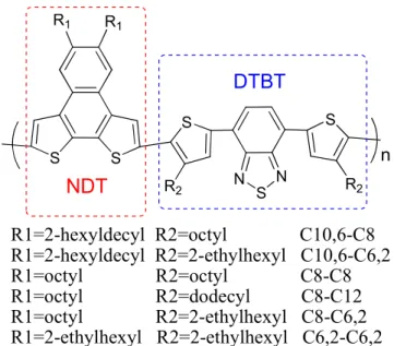
backbone. The conjugated backbone of these polymers (PNDT-DTBT) is constructed following the weak donor-strong acceptor strategy35,96,97, by alternating naphtho[2,1-b:3,4-b']dithiophene (NDT) and 4,7-di(thiophen-2-yl)benzothiadiazole (DTBT) (Fig. 2.1). The alkyl chains are attached to the 4th position of these thienyl groups on DTBT to minimize the steric hindrance to the polymer backbone and hence to maintain near identical band gap and energy levels (as decided by the conjugated backbone)35. Surprisingly, the observed Voc and Jsc of these PNDT-DTBT based BHJ devices vary as
much as 100%, depending upon the length and shape of the alkyl side chains. Consequently, the overall efficiency of PNDT-DTBT polymers/PC61BM based solar cells
has shown a significant variation as much as 2.5 fold (from 1.20% to 3.36%). More importantly, the observed difference in Voc and Jsc has been quantitatively correlated with
a pre-exponential dark current term, Jso, which accounts for the intermolecular
experimental values within 10% error, which clearly demonstrate the predictive power of this quantitative analysis.
Figure 2.1. The chemical structures of the six polymers based on the PNDT-DTBT backbone.
2.2. Experimental Section
Glass substrates coated with patterned indium-doped tin oxide (ITO) were purchased from Thin Film Devices, Inc. The 150 nm sputtered ITO pattern had a resistivity of 15Ω/□. Prior to use, the substrates were ultrasonicated for 20 minutes in acetone followed by deionized water and then 2-propanol. The substrates were dried under a stream of nitrogen and subjected to the treatment of UV-Ozone over 30 minutes. A filtered dispersion of PEDOT:PSS in water (Baytron PH500) was then spun cast onto clean ITO substrates at 4000 rpm for 60 seconds and then baked at 140 °C for 10 minutes to give a thin film with a thickness of 40 nm. A blend of polymer and PC61BM (1:1 w/w,
10 mg/mL for polymers) was dissolved in chlorobenzene with heating at 100 °C for 6 hours. All the solutions were spun cast at 1100 rpm for 60 seconds onto PEDOT:PSS
S S N S N S S n R1 R1 R2 R2 R1=2-hexyldecyl R2=octyl C10,6-C8 R1=2-hexyldecyl R2=2-ethylhexyl C10,6-C6,2 R1=octyl R2=octyl C8-C8 R1=octyl R2=dodecyl C8-C12 R1=octyl R2=2-ethylhexyl C8-C6,2 R1=2-ethylhexyl R2=2-ethylhexyl C6,2-C6,2 NDT DTBT
layer. The substrates were then dried at room temperature in the glovebox under nitrogen atmosphere for 12 hours. The devices were finished for measurement after thermal deposition of a 30 nm film of calcium and a 70 nm aluminum film as the cathode at a pressure of ~ 1×10⁻⁶ mbar. There are 8 devices per substrate, with an active area of 12 mm2 per device. Device characterization was carried out under AM 1.5G irradiation with the intensity of 100 mW/cm2 (Oriel 91160, 300 W) calibrated by a NREL certified standard silicon cell. Current versus potential (I-V) curves were recorded with a Keithley 2400 digital source meter. EQE were detected under monochromatic illumination (Oriel Cornerstone 260 ¼ m monochromator equipped with Oriel 70613NS QTH lamp) and the calibration of the incident light was performed with a monocrystalline silicon diode. All fabrication steps after adding the PEDOT:PSS layer onto ITO substrate, and characterizations were performed in gloveboxes under nitrogen atmosphere. For more experimental details about reagents, instrumentation, electrochemistry, and spectroscopy please check Appendix A.
2.3. Optical and Electrochemical Properties of Polymers
Figure 2.2. Normalized absorption spectra of polymer solutions in trichlorobenzene at a) 140 ºC and b) room temperature.
300 400 500 600 700 800 0.0 0.2 0.4 0.6 0.8 1.0 1.2 N o rm a liz e d A b s o rp ti o n ( a .u .) Wavelength (nm) C10,6-C8 C10,6-C6,2 C8-C8 C8-C12 C8-C6,2 C6,2-C6,2 300 400 500 600 700 800 0.0 0.2 0.4 0.6 0.8 1.0 1.2 1.4 C10,6-C8 C10,6-C6,2 C8-C8 C8-C12 C8-C6,2 C6,2-C6,2 N o rm a liz e d A b s o rp ti o n ( a .u .) Wavelength (nm)
a
b
At high temperature and in good solvent, the effect of solubilizing chains on conjugated polymers has little impact on the optical properties since the polymers are adequately solvated. Thus all absorption spectra of these polymers collapse together, indicative of the identical PNDT-DTBT backbone (Fig. 2.2a). However, dramatic effects were observed on the optical properties of polymer, when these polymer solutions of identical concentration are cooled to room temperature. For example, polymer C8-C8 with short straight side chains exhibits much stronger aggregation when compared with C10,6-C6,2, as indicated by a pronounced absorption increase at longer wavelengths from about 700 nm to almost 800 nm. The observed differences on the optical properties of polymer with different size of side chains will be further discussed in the following sections.
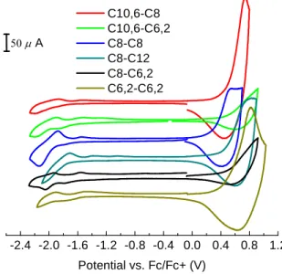
Figure 2.3. Cyclic voltammograms of the oxidation and reduction behavior of thin films
The polymerization results of all polymers are listed in Table 2.1. The synthesis of all six polymers was controlled to get a similar molecular weight in order to minimize the effect of molecular weight on the photovoltaic performances. Probing this library of polymers with identical conjugated backbone via cyclic voltammetry provides direct evidence on how the difference in shape and length of these alkyl chains affects the
-2.4 -2.0 -1.6 -1.2 -0.8 -0.4 0.0 0.4 0.8 1.2 50 µ A Potential vs. Fc/Fc+ (V) C10,6-C8 C10,6-C6,2 C8-C8 C8-C12 C8-C6,2 C6,2-C6,2
energy levels of these related polymers (Fig. 2.3). Table 2.1 summarizes the energy levels of LUMO and HOMO observed from cyclic voltammetry and computational study (see Appendix B Fig. B.1). The calculated values of the HOMO and LUMO exhibit similar trend to the corresponding experimental data, a clear indication of the viability and effectiveness of these electrochemical data. Interestingly, the shape and length of attached solubilizing alkyl chains on the DTBT unit seemingly has little impact on the electrochemical properties of related polymers, due to the limited steric hindrance introduced by the side chain on 4th position of the polymer backbone.35
Table 2.1. Calculated and measured electrochemical data of all polymers.
Polymer Mn (Kg/mol) PDI HOMO(eV) Cal HOMO (eV) Exp LOMO (eV) Cal LOMO (eV) Exp C10,6-C8 11.9 1.83 -5.15 -5.32 -2.85 -3.12 C10,6-C6,2 10.6 1.77 -5.16 -5.33 -2.89 -3.20 C8-C8 12.4 2.23 -5.04 -5.13 -2.86 -3.19 C8-C12 15.4 3.03 -5.02 -5.27 -2.84 -3.12 C8-C6,2 5.24 1.91 -5.16 -5.30 -2.88 -3.21 C6,2-C6,2 6.76 2.07 -5.17 -5.34 -2.90 -3.26
2.4. Measured and Calculated Photovoltaic Properties of All Devices
The generalized Shockley equation (equation (2.1))101,102 can be used to describe the current density (J) vs. voltage (V) characteristics of organic solar cells:
(
)
exp
1
( )
p s s ph s p pR
q V
JR
V
J
J
J
V
R
R
nkT
R
−
=
−
+
−
+
(2.1)Here, Rp is the parallel resistance, Rs is the series resistance, Js is the saturation current