© 2016, IRJET | Impact Factor value: 4.45 | ISO 9001:2008 Certified Journal | Page 379
POWER QUALITY IMPROVEMENT USING AC- DC BOOST CONVERTER
Ankita A. Yeotikar
1, Swapnil B. Mohod
21
PG Student, Electrical and Electronics Engg., PRMCEAM Badnera, Maharashtra, India
2Asst. Professor, Electrical and Electronics Engg. Deptt., PRMCEAM Badnera, Maharashtra, India
---***---Abstract:
Power factor correction (PFC) is a mandatoryfunctionality of electronic products in the industrial and commercial market in order to mitigate grid harmonics to improve power quality. Since the load characteristics of most PFC applications such as home appliances, battery chargers, switched mode power supplies and other digital products support unidirectional power flow, the general ac-dc boost converter is considered a popular topology. It is one of the low cost, simple methodologies and their performance is well-proven. Maintaining dc-link voltage constantly inside the system in order to feed loads at different power ratings is the main task. Active power filters (APF) is another approach capable of improving grid power quality to control input current with a pure sinusoidal waveform in phase with input voltage. Unlike PFC circuits, the APF is a system in itself which provides compensation of harmonics and reactive power in order to reduce undesirable effects from non-linear loads and uncontrolled passive loads in power systems. The paper introduces a versatile method for mitigating grid power quality using unidirectional ac – dc boost converter. The additional focus of this paper is to measure the quantity of input current distortions by the unidirectional ac – dc boost converter used for supplying active power to the load and reactive power. By using this method, the amount of reactive power injected due to input current distortion from an individual converter to the grid should be restricted.
Key Words: Active power filter (APF), cusp distortion,
harmonic current compensation (HCC), power factor correction (PFC), reactive power compensation (RPC), unidirectional ac - dc boost converter.
1. INTRODUCTION
Reactive power compensation is important not only for power system stability but also efficient use of the power transmitted through the electric grid [2]. Although many power electronics based technologies such as flexible alternating current transmission systems and active power filters have emerged to overcome the shortcomings of traditional passive shunt compensation methods, they may not be the best solution for improvement of power quality of an entire power system due to high capital and operating costs, as well as additional inherent power losses.
In this paper, reactive power capabilities of existing aggregated unidirectional converters is investigated and a cost effective solution for reactive power compensation through control and integration strategies for unidirectional in residential distributed power systems is proposed [9]. Usually, unidirectional power factor correction converters are utilized in many commercial applications such as laundry machines, air conditioners, and battery chargers as front end circuitry in order to minimize the effects of harmonic distortion and poor power factor caused by their respective nonlinear loads. Since these converters are found everywhere, they have great potential as reactive power resources in distribution level power systems if they possess reactive power compensation functionality. Ultimately, residential power systems will possess the ability to act as large reactive power compensators, resulting in more efficient and stable electric power distribution system.
Traditional reactive power compensation methods include rotating synchronous condensers and fixed or mechanically switched capacitors or inductors [12]. However, there are limitations in both dynamic and steady-state performance, because these methods use mechanical devices with little or no high-speed controllability. In addition, these mechanical devices cannot be switched frequently due to their low durability. To overcome the demerits of traditional technologies, several power electronics based technologies have been developed to enhance the controllability and power transfer capability in transmission and distribution systems.
© 2016, IRJET | Impact Factor value: 4.45 | ISO 9001:2008 Certified Journal | Page 380
costs related to space and installation, as well as additionalinherent power losses. Moreover, a local supply of reactive power from distribution systems or micro grids in response to local voltage signals is more desirable and economical rather than remote VAR transmission methods, because local reactive power supply can significantly reduce feeder losses [14].
To find better economical solutions, the demands of power quality mitigation have continuously encouraged power electronics engineers to include HCC and RPC capabilities in power converters typically used for renewable energy conversion systems such as wind turbines, photovoltaic (PV) and fuel cell systems. These may have HCC and RPC functionalities as ancillary services, usually typical of converters capable of bidirectional power flow. As power converters for renewable energy sources become more popular in ac power systems, the potential for HCC and RPC will greatly increase, as these control schemes can be employed in existing topologies without hardware changes, while simultaneously sending generated energy back to the grid [6]. Despite the increased utility and cost savings, the number of renewable power converters capable of fulfilling these functions is still limited.
Alternatively, vehicle-to-grid (V2G) technology has recently emerged for incorporation of electric vehicles into the electric grid as energy storages which can mitigate power quality as an ancillary service [7]. This will result in enhanced reliability and performance of the power system. However, V2G require a bidirectional power converter, which increases system cost and complexity compared to that of a unidirectional power converter. For this reason, a unidirectional topology is a preferable configuration for level 1 battery chargers in electric vehicle (EV) and plug-in electric vehicle (PHEV) applications, meant for residential interconnections, whereas V2G utilizing bidirectional converters is more applicable for level 2 battery chargers.
Power factor correction (PFC) converters are embedded in the commercial products such as home appliances, EV/PHEV battery chargers, and switched mode power supplies to regulate the input current to be sinusoidal waveform in phase with the grid voltage in unidirectional power flow capability. Since numerous unidirectional converters are connected with ac power systems, if we can utilize the reactive power capacity of PFC circuits, then existing unidirectional ac-dc boost converters have great potential to improve substantially the stability of ac power systems. In recent years, few papers have detailed HCC and RPC functionalities using unidirectional PFC converters in. In[7] battery charger topologies used for EV/PHEV applications have been reviewed for providing reactive power support to the grid, but the RPC capability in unidirectional converters was mentioned briefly.
2. CONTROL ALGORITHM
© 2016, IRJET | Impact Factor value: 4.45 | ISO 9001:2008 Certified Journal | Page 381
Fig. 1: Proposed system connected to linear and nonlinearloads.
The dual boost PFC converter is one of the most popular unidirectional ac–dc boost converters. Fig. 1 shows a prevalent application of unidirectional ac–dc boost converters. Conventional PFC converters consider the input current to be a purely sinusoidal waveform, which is completely in phase with the input voltage. The proposed control method can improve harmonic current and reactive power for improved grid power quality, as well as regulation of dc-bus voltage. The proposed versatile control of unidirectional ac–dc boost converter has three modes of operation, i.e., PFC, HCC, and RPC. Also, both HCC and RPC can operate simultaneously to improve the distortion and the displacement factors of the grid current.
2.1. PFC Control
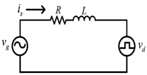
PFC control methods are very common in the related literature, especially those utilizing feedback and feedforward controllers as shown in Fig. 2. Fig. 3 depicts a simple circuit diagram of unidirectional ac–dc boost converters with an input inductor L and its parasitic resistor R. Kirchhoff’s voltage law with the source voltage vg, the
switch voltage vd, and the input line current yields to
vg = Ris + L*dis/dt + vd (1)
Where, vg is the instantaneous value of the source voltage
expressed as Vgsin(ωt). The switch voltage is always a major
factor in determining the waveform of the input current. In other words, when producing a sinusoidal input current, the switch voltage has to emulate the source voltage identically, with the exact phase difference due to input impedance. The average switch voltage over a switching cycle in continuous conduction mode can be expressed as
vd = (1−d) * vdc (2)
where, d is the average on-time duty ratio of the switches and vdc is the dc output voltage. When the source voltage is
in the negative half period, the sign of the input current and switch voltage will be opposite. Therefore, the source voltage can be considered as a rectified voltage , which can be expressed by the absolute sign. Combining (1) and (2), and rearranging in terms of d, the duty ratio equation can be obtained as
(3)
In order to classify the duty ratio d of the system in (3), the feedback duty ratio dFB and the feed forward duty
ratio dFF can be considered separately. dFB produces the exact
phase difference between the source voltage and the average switch voltage. dFF produces the inverse of the source voltage
[image:3.595.329.536.328.422.2]waveform as the average switch voltage. Hence, the input current tracking is improved and the frequency range for which input admittance acts purely as a resistance can be extended to higher frequencies due to feedforward control.
Fig. 2: Conventional control algorithm for unidirectional ac–dc boosts converters.
Fig. 3: Simple circuit diagram during a positive half period of the source voltage.
2.2. Harmonic Current Compensation
Generally, the distorted load current inon can be
written in terms of its fundamental ifn and harmonic ihn
components as
inon = I1 sin (ω1t + θ1) + (4)
where, ω1 is the line angular frequency and θn is the phase
difference between the source voltage and input current. Assume that the input current from the unidirectional ac–dc boost converter operating in PFC mode is a purely sinusoidal waveform. The grid current ig includes ihn from a nonlinear
[image:3.595.358.509.465.542.2]© 2016, IRJET | Impact Factor value: 4.45 | ISO 9001:2008 Certified Journal | Page 382
generate the harmonic current capable of canceling theharmonics of the non linear load, the grid current will be comprised of only fundamental components of the converter current and load current. Therefore, the new current reference for the current controller of the converter can be expressed as
is* = Is* sin (ωt) – ihn (5)
where, Is* is the magnitude reference provided by the dc-bus
voltage controller.
2.3 Reactive Power Compensation
Unlike nonlinear loads, the current waveform of a linear load is sinusoidal at the frequency of the power system, but the power factor can be significantly exacerbated when the load is capacitive or inductive. As a result, the grid power factor at the PCC can be improved by injecting reactive power from the converter [2]. However, it should be considered that the input current of the unidirectional converter becomes distorted due to the natural commutation of diodes; thus, the amount of reactive power generated by an individual converter should be restricted. The phase angle reference to the input converter current needs to be generated by employing a proportional integral compensator as
Ø = Kpc (Q* - Q) + Kic (6)
is* = Is* sin (ωt + Ø) (7)
where, Kpc and Kic are proportional gain and integral gain of
the reactive power compensator, respectively, and φ is the desired phase to be adjusted from the original current reference. It should be noted in (7) that the current magnitude reference Is* will be adjusted through the dc-bus
voltage controller to feed active power to the dc load. The reactive power will be adjusted by changing the phase angle φ.
2.4. Control Strategy for APF Functionality
The proposed control strategy of the unidirectional ac – dc converter including a feedforward controller, HCC, and RPC is shown in Fig. 4 [9]. Two control blocks for HCC and RPC have been added to the conventional control algorithm in Fig.2.Thus, the final current reference for a versatile control strategy based on (5) and (7) can be expressed as
[image:4.595.316.555.95.240.2]is* = Is* sin (ωt + Ø) - ihn (8)
Fig. 4: Proposed HCC and RPC control block diagram.
3. SIMULATION RESULT
Simulation results shows that input power quality is improved through the proposed IIC feedforward control using ac-dc boost converter. In addition, the proposed IIC feedforward method can be utilized easily with simple modification of the existing voltage feedforward equation. Consequently, these features make the proposed IIC feedforward method extremely fit for digital implementation in ac-dc boost converters with limited bandwidth.
[image:4.595.316.550.407.530.2]
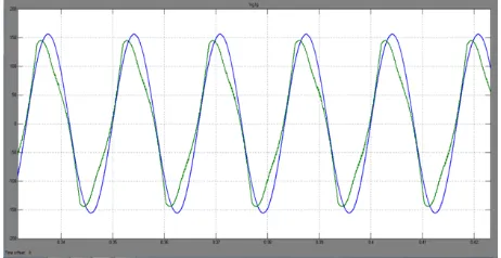
Fig.5: Input grid voltage without ac – dc boost converter
[image:4.595.318.549.568.687.2]© 2016, IRJET | Impact Factor value: 4.45 | ISO 9001:2008 Certified Journal | Page 383
Fig. 7: Power factor nearer to unityFig. 8: THD without ac – dc boost converter
Fig. 9: THD with ac – dc boost converter
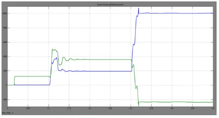
Fig. 10: Active and reactive power
4. CONCLUSION
Since unidirectional ac-dc boost converters are ubiquitously connected with ac power systems, possess the ability to improve substantially the stability of ac power systems by maximizing functionalities of aggregated unidirectional ac-dc boost converters. A versatile control methods for the unidirectional ac-dc boost converter have been presented to enhance grid power quality through the combination of HCC and RPC, which can be a more economical solution for future smart grid applications. In addition, the framework for evaluation of the current distortion levels in unidirectional ac-dc boost converters when they are employed for RPC has been presented. Simulation results shows improved power factor and total harmonic distortion of the grid. At the same time, it should be noted that due to the inherent limitations of the unidirectional ac-dc boost converter, the grid current will be distorted unintentionally when operating in RPC mode where the THD of capacitive current is worse than that of the inductive current due to extended cusp distortions. Hence, the amount of reactive power injected from an individual converter to the grid should be restricted. Although, combined operation of these aggregated converters, each restricted in RPC, can meet the reactive power demand while still effectively compensating for generated harmonics.
REFERENCES:
[1]. B. Singh, K. Al-Haddad, and A. Chandra, “A review of active filters for power quality improvement,” IEEE Trans. Ind. Electron., vol. 46, no. 5, pp. 960–971, Oct. 1999.
[2]. J. Dixon, L. Moran, J. Rodriguez, and R. Domke, “Reactive power compensation technologies: State-of-the-art review,” Proc. IEEE, vol. 93, no. 12, pp. 1244– 1264, Dec. 2005.
[3]. L. Gyugyi, “Power electronics in electric utilities: Static VAR compensators,” Proc. IEEE, vol. 76, no. 4, pp. 483– 494, Apr. 1988.
[4]. M. El-Habrouk, M. K. Darwish, and P. Mehta, “Active power filters: A review,” Proc. Inst. Elect. Eng.—Electr. Power Appl., vol. 147, no. 5, pp. 403–413, Sep. 2000. [5]. M. M. Jovanovicand, Y. Jang,“State-of-the-art, single -
phase, active power factor - correction techniques for high - power applications—An overview,” IEEE Trans. Ind. Electron., vol. 52, no. 3, pp. 701–708, Jun. 2005. [6]. M. Singh, V. Khadkikar, A. Chandra, R. Varma, “Grid
interconnection of renewable energy sources at the distribution level with power quality improvement features,” IEEE Trans. on power delivery, vol. 26, no. 1, january 2011.
[image:5.595.51.275.428.579.2] [image:5.595.49.275.610.732.2]© 2016, IRJET | Impact Factor value: 4.45 | ISO 9001:2008 Certified Journal | Page 384
[8]. P. Acuna, L. Moran, M. Rivera, J. Dixon, and J. Rodriguez,“Improved active power filter performance for renewable power generation systems,” IEEE Trans. Power Electron., vol. 29, no. 2, pp. 687–694, Feb. 2014. [9]. Park and park, “Versatile control of unidirectional ac–
dc boost converters for power quality mitigation,” IEEE Trans. Power Electron., vol. 30, no. 9, Sept. 2015. [10]. P. S. Sensarma, K. R. Padiyar, and V. Ramanarayanan,
“Analysis and performance evaluation of a distribution STATCOM for compensating voltage fluctuations,” IEEE Trans. Power Del., vol. 16, no. 2, pp. 259– 264, Apr. 2001.
[11]. R. Majumder, “Reactive power compensation in single-phase operation of microgrid,” IEEE Trans. Ind. Electron., vol. 60, no. 4, pp. 1403–1416, Apr. 2013. [12]. R. Shilpa, P. S. Puttaswamy, “A review on power quality
issues in power systems,” International Journal of Industrial Electronics and Electrical Engineering, ISSN: 2347-6982, vol. 2, Issue-10, Oct. 2014.
[13]. S. Arunraj, “Novel trends on unidirectional ac–dc boost converters using fuzzy logics for power quality mitigation,” International Journal On Engineering
Technology and Sciences ISSN (P) : 2349-3968, ISSN (O): 2349-3976 vol. II, Issue X, Oct. 2015.
[14]. Y. Dubey, T. Gajpal, “Applications of smart grid through harmonic current & reactive power compensation,” IJMTS, ISSN: 2455-3778, vol. 2, Issue- 05, May 2016.