© 2017, IRJET | Impact Factor value: 5.181 | ISO 9001:2008 Certified Journal | Page 1568
Design & Thermal Analysis of I.C. Engine Poppet Valves using Solidworks and FEA
Ch. Mani Kumar
1P. Rajendra Babu
21,2
Asst. Professor, Dept. of Mechanical Engineering, Sasi Institute of Technology and Engineering, AP, India
---***---Abstract -
Intake and exhaust valves in I.C. enginesare called as poppet valves. These valves are operated by valve mechanism. When these valves are exposed to the heat thermal stresses are developed so that thermal analysis is very important to predicting and preventing failures in valves. This paper aims to model and simulates the thermal analysis on poppet valves applications of 99.3cc. Modeling of the valves was done in the solidworks and thermal analysis was carried
out in the ANSYS. In thermal analysis determined directional
heat flux, total heat flux and temperature. Here used three materials for each valves and suggested best material for each valves on basis of thermal point of view.
Keywords
:
Inlet valve, Exhaust valve, Composite materials, Ceramics, Solidworks, and FEA.I.
INTRODUCTION
The valves used in internal combustion engines are of the three types
1. Poppet or mushroom valve 2. Rotary valve
3. Sleeve valve
Out of these three valves, poppet valve is very frequently used. It possesses certain advantages over the other valve types because of which it is extensively used in the automotive engines. The advantages are;
1. Simplicity of construction 2. Self-centering.
3. Free to rotate about the stem to the new position. 4. Maintenance of sealing efficiency is relatively easier.
Sanoj.T et al (2014) analyzed the stress induced in a valve due to high thermal gradient and high pressure inside the combustion chamber. In the first stage of analysis the temperature distribution across the valve was determined. In the second stage found displacement [1].
Deepak Bhargav et al (2016) they evaluated for uncoated and coated engine valve with and without the application of bond coat. From the results decrease in heat flux, mechanical stress and total deformation the with coated engine valve with bond coat while increased in stress were observed. Bond coat gave better wear and corrosion resistance [2].
Sagar.S Deshpande
, et al (2014) Analyzed the effect ofvaried materials and geometric parameters on mechanical properties of poppet engine valve to improve its performance over life and fatigue life using Ansys software [1].
B Seshagiri Rao et al (2014) they had designed the exhaust valve for four wheeler petrol engine using theoretical calculations. 3D model and transient thermal analysis is to be done on the exhaust valve when valve is open and closed. Study state condition is attained at 5000 cycles at the time of when valve is closed is 127.651 seconds valve is opened 127.659 seconds. The material was used for exhaust valve is EN52 steel [3].
Karan Soni et al (2015) they conclude valve design can be optimized to reduce its weight, without affecting permissible stress and deformation values. Due to reduction in strength improves the valve strength [4]
.
II. DESIGN CONSIDERATIONS
II.I Specifications Engine specification:
1 Make TVS
2 Model Luna
3 Displacement 97.22 cc 4 Bore &stroke 50 x 49.5 mm 5 Compression ratio 8.8 : 1
6 Swept Volume 97193.02272 mm³ 7 Clearance Volume 12460.64394 mm³ 8 Theoretical Efficiency 58.1
Exhaust valve dimensions Diameter of the valve= 10.4mm
Distance between the groove= 9.8mm Base diameter= 23.2mm
Diameter above the base=9.8mm Total length of the valve=66.4mm
Length of the stem=47.2mm Thickness of valve disc=2.4mm
© 2017, IRJET | Impact Factor value: 5.181 | ISO 9001:2008 Certified Journal | Page 1569 Distance between the groove= 9.8mm
Base diameter= 20mm
Diameter above the base=9.6mm Total length of the valve=67mm
Length of the stem=42mm Thickness of valve disc=2mm
II.2. 2D Model
Fig.1. Inlet valve Fig.2. Exhaust valve
II.3. 3D model
Fig.3. Inlet valve Fig.4. Exhaust valve
II.4. Methodology
Fig. 5. Thermal analysis process flow chart for poppet valves
II.5. Modeling
The 3-D modeling was done by using Solidworks software.
II.6. Meshing
The components were meshed by using ANSYS software.
II.7. FEM analysis
Fig.6. Proposed meshing (Tetrahedral element) of Inlet Valve
© 2017, IRJET | Impact Factor value: 5.181 | ISO 9001:2008 Certified Journal | Page 1570 The, temperature, total heat flux and directional heat flux are
very important for poppet valve. To meet these requirements to perform thermal analysis on stainless steel and ceramic composite materials of poppet valves. The finite element analysis was carried out by using Ansys software. This thermal analysis was performed based on the following assumptions.
In thermal analysis the max temperature is 900 and mini. Temperature is 300 for exhaust valve and 60 and 750 mini and max temperatures for inlet valve respectively.
III. MATERIAL
III.1. Inlet valve
Steel
1 Density in (kg/cm³) 7.6 2 Young’s modulus in (GPa) 190 3 Poissons ratio 0.25 4 Thermal conductivity in (W/m- K) 12-45 5 Coefficient of linear expansion in
(µm/m- °C)
11-12.5
Alumina
1 Density in (kg/cm³) 3.7- 3.97 2 Young’s modulus in (GPa) 393 3 Poissons ratio 0.27 4 Thermal conductivity in (W/m- K) 35 5 Coefficient of linear expansion in
(µm/m- °C) 8.4
Silicon
1 Density in (kg/cm³) 2.3 2 Young’s modulus in (GPa) 160 3 Poissons ratio 0.17 4 Thermal conductivity in (W/m- K) 149 5 Coefficient of linear expansion in
(µm/m- °C)
2.6
III.2. Exhaust valve Stainless steel
1 Density in (kg/cm³) 7.6 2 Young’s modulus in (GPa) 190
Poissons ratio 0.25 3 Thermal conductivity in (W/m- K) 12-45 4 Coefficient of linear expansion in
(µm/m- °C) 11-12.5
Silicon Nitride
1 Density in (kg/cm³) 3.31 2 Young’s modulus in (GPa) 317
3 Poissons ratio 0.23 4 Thermal conductivity in (W/m- K) 27 5 Coefficient of linear expansion in
(µm/m- °C) 3.4
Aluminum nitride
1 Density in (kg/cm³) 3.25 2 Young’s modulus in (GPa) 308 3 Poissons ratio 0.25 4 Thermal conductivity in (W/m- K) 82.3 - 170 5 Coefficient of linear expansion in
(µm/m- °C) 4.6- 5.7
II.8. Boundary Conditions
The boundary conditions were considered under the head and at the neck (tappets located area) portion of the both the valves in thermal. The boundary conditions are shown in the respective figures.
Fig.8. Boundary conditions
IV. Results and Discussion
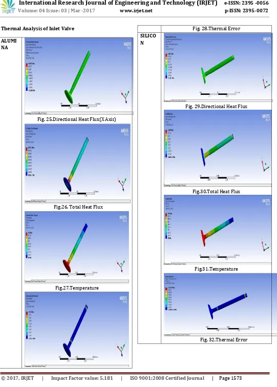
Fig10, 14 and 22 shows the total heat flux rate of three materials for exhaust valve as well as fig 26, 30 and 34 shows the amount total heat flux rate of three materials for inlet valve. The maximum heat flux of Aluminum Nitride for exhaust valve is 2.511 W/mm2 and the maximum heat flux
© 2017, IRJET | Impact Factor value: 5.181 | ISO 9001:2008 Certified Journal | Page 1571
Thermal Analysis of Exhaust Valve
ALUMINI UM NITRIDE
Fig.9. Directional heat flux(X axis)
Fig.10. Total Heat Flux
Fig.11. Temperature
Fig.12.Thermal Error
SILICON NITRIDE
Fig.13. Directional heat flux(X Axis)
Fig.14. Total heat flux
Fig.15.Temperature
© 2017, IRJET | Impact Factor value: 5.181 | ISO 9001:2008 Certified Journal | Page 1572 Fig.17.Temperature
Fig. 18.Total Heat Flux
Fig.19. Directional Heat
Fig. 20.Thermal Error
Stainless Steel
Fig.21. Directional Heat Flux
Fig.22 Total Heat Flux
Fig.23.Temperature
© 2017, IRJET | Impact Factor value: 5.181 | ISO 9001:2008 Certified Journal | Page 1573
Thermal Analysis of Inlet Valve
ALUMI NA
Fig. 25.Directional Heat Flux(X Axis)
Fig.26. Total Heat Flux
[image:6.595.34.575.50.805.2]Fig.27.Temperature
Fig. 28.Thermal Error
SILICO N
Fig. 29.Directional Heat Flux
Fig.30.Total Heat Flux
Fig.31.Temperature
© 2017, IRJET | Impact Factor value: 5.181 | ISO 9001:2008 Certified Journal | Page 1574
[image:7.595.33.303.96.678.2]STEEL
Fig.33. Directional Heat Flux(X Axis)
Fig.34. Total Heat Flux
Fig.35.Temperature
© 2017, IRJET | Impact Factor value: 5.181 | ISO 9001:2008 Certified Journal | Page 1575
Table: 1. Thermal Analysis of Inlet valve for three materials
Table: 2. Thermal Analysis of exhaust valve for three materials
VI. CONCLUSION
In this paper the 3D model of poppet valve were designed by using Solidworkssoftware. The model is meshed by using ANSYS. The FEA was done by ANSYS. The thermal analysis was successfully carried out to determine the total heat flux, directional heat flux and temperature distribution on the valves. Both the valves were analyzed with different materials. Compared and suggested best material for both the
valves.
In this study found out, in thermal analysis maximum heat flux was observed in steel (0.48813 W/mm²) for inlet valve and for exhaust valvestainless steel (0.64196 W/mm²).From the above results it was observed that the steel is the best material for inlet valve and for exhaust valve stainless steel.
REFERENCES
[1] Sanoj. T1 , S. Balamurugan “Thermo Mechanical Analysis
of Engine Valve” International Journal of Science and Research Volume 3 Issue 5, May 2014
[2] Deepak Bhargav1, Anurag Singh Rana1, Chirag
Narayana1, Nikhil Sharma1 and Amit Sethi 2Design and Performance Evaluation of Thermal Barrier Coated Engine Valve Using Finite Element AnalysisInternational Journal of Innovative Research in Science,Engineering and Technology Vol. 5, Issue 5, May 2016
[3] Sagar.S Deshpande , Vidyadhar. C. Kale , K.V. Chandratre
“Analysis Of Stress Concentration Factor For Engine Valve Designs For Improved Fatigue Strength ”
S. No
Material Temperature
in (°C)
Total Heat Flux in (W/mm²)
Directional Heat Flux in (W/mm²)
Thermal Error
Mini Max Mini Max Mini Max Mini Max
1.
Alumina 60 750 6.886e -007 0.9057 5
-0.42843 0.4267 3
1.3251e -006
165.1 2 2. Silicon 60 750 1.6026e -006 3.3878 -2.3163 2.3072 1.6807e
-006
1133. 9
3. Steel 60 750 4.7565e -007 0.4881 3
-0.15888 0.1502 1.4689e – 006
166.9 9
S. No
Material Temperatur
e in (°C)
Total Heat Flux in (W/mm²)
Directional Heat Flux in (W/mm²)
Thermal Error
Mini Max Mini Max Mini Max Mini Max
1.
Aluminum Nitride
300 900 7.2716e -008 2.5113 -1.0193 0.96596 4.7209e -009 2018. 2 2. Silicon Nitride 300 900 3.7755e -008 0.88298 -0.28035 0.27485 5.9741e -009 320.4
5
© 2017, IRJET | Impact Factor value: 5.181 | ISO 9001:2008 Certified Journal | Page 1576 International Journal of Modern Trends in Engineering
and Research, Volume 2, Issue 7, [July - 2015] Special Issue of ICRTET’2015
[4] Snehal S.Gawale , Dr.S.N.Shelke, Prof.M.A.Ahire “Design
Of Stationary Ic Engine’s Exhaust Valve and Optimization Based on Finite Element Analysis” Volume 3, Issue 4, [April 2016] Special Issue of ICRTET’2016 International Journal of Modern Trends in Engineering and Research
[5] B Seshagiri Rao* and D Gopi Chandu “PETROL ENGINE
EXHAUST VALVE DESIGN, ANALYSIS AND MANUFACTURING PROCESSES “International journal of Mechanical and Robotics Researchh, Vol. 3, No. 4, October, 2014 © 2014 IJMERR.
[6] Karan Soni* , S. M. Bhatt**, Ravi Dayatar***, Kashyap