© 2017, IRJET | Impact Factor value: 5.181 | ISO 9001:2008 Certified Journal
| Page 1467
ANALYTICAL STUDY OF CONVENTIONAL SLAB AND BUBBLE DECK SLAB
UNDER VARIOUS SUPPORT AND LOADING CONDITIONS USING ANSYS
WORKBENCH 14.0
Sameer Ali
1, Manoj Kumar
21
PG Student, Structural Engineering, Integral University, Uttar Pradesh, India
2
Assistant professor, Department Of Civil Engineering, Integral University, Uttar Pradesh, India
---***---Abstract
- The objective of this study is to perform thebehavioral analysis of conventional slab and bubble deck slab using ansys workbench 14.0. This comparative study includes the study of normal slab and slab with HDPE spherical ball at center to form voids. Normally the Bubble Deck framework consolidates the advantages of production line made components in controlled conditions alongside on location site with reduced quantity of concrete. High Density polyethylene (HDPE) empty sphere replaces the ineffective concrete at neutral axis of the slab section, in this way diminishing the dead weight. Simply supported End conditions are assumed for both slabs under Static (udl) loads. The analysis result showed the total deflection ,Von-mises Stress of both slab under uniformaly distributed load for different end conditions. This paper moreover displays a review on the properties and preferences of Bubble Deck section over conventional slab.
Key Words: Bubble Deck Slab, Finite Element Method , Voided slab , Structural behaviour , HDPE sphere balls.
1. INTRODUCTION
The finite element method is a numerical techniques ever devised for solving differential as well as integral equation of initial and different boundary value problems in a very geometrically complicated conditions .some factors that cannot be ignored when analysing an element by the finite element method. This data is to define the domain and the boundary and initial condition and also the physical properties of specimen. After knowing this data, if the analysis is done carefully, it will give the satisfactory result. It can also be said that the finite element analysis is very methodical and that it is why is so popular, because that makes it easier to apply. In finite element analysis problem is systematically divided into a set of logical steps that can be implemented on a digital computer and can be utilized to solve a wide range of problems by merely changing the data input to the software.
The finite element analysis is used for one, two and three-dimensional problems. Sometimes the easier problems are including one and two dimensions problems and can be
solved without software if they are handled with care, an exact result can be achieved. But if the analysis requires three-dimensional tools, then it would be a lot more complicated, because it will involve a lot of equation that are very difficult to solve without having an errors.
Because of this software have developed that can perform these analyses by computer, making everything easier. This software can make analysis of one, two and three dimensional problems with a very good accuracy.
A basic fundamental of finite element works is that it divides the whole element into a finite number of small elements. The domain of the problem is viewed as a collection of nonintersecting simple sub domains, called finite element. The subdivision of a domain into elements is termed finite element discretization. The collection of the elements is called the finite element mesh of the domain. The benefit of dividing a big element into small ones is that it allows that every small element has a simpler shape, which leads to a good approximation for the analysis. Another advantage is that at every node (the intersection of the boundaries) arises an interplant polynomial, which allows an accurate result at a specific point.
The invention of bubble deck slab was a breakthrough at the turn of 20th and 21st centuries. During the 1st decade there have been many studies on the feasibility of using the bubble deck technology.
In any structure, slabs are the essential individuals utilized for berthing reason and furthermore used to transmit the stacking and loading to other basic individuals structural members. According to the reviews played out, the concrete at mid of the section is not completely used. The concrete that is set in tension zone is expected to convey no load and thus unused. The unused concrete may impart up to 80% of the total volume of concrete. This unused concrete can't be completely expelled as it decreases the Load carrying capacity at conveying limit and furthermore increases the deflection. So an incomplete volume of this unused concrete can be supplanted by conceivable method of providing void formers which merely create voids.
© 2017, IRJET | Impact Factor value: 5.181 | ISO 9001:2008 Certified Journal
| Page 1468
and it ends in increased column and foundation size. Thus, itmakes structure consume more concrete and steel.
Now, this innovative technology has been applied to only few residential or high rise buildings, and industrial floor slab due to limited understandings. For this investigation, the structural behavior of Bubble Deck under various loading conditions will be analysed in order to gain understanding on this technique and to compare it to the current slab system.
2. TYPES OF BUBBLE DECK
All of the Bubble Deck versions come in three forms- Filigree elements, reinforcement modules, and finished planks.
For all types of Bubble Deck, the maximum element size for transportation reasons is 3 m. Once the sections are connected on site however, there is no difference in the capacity.
Type A- Filigree Elements
Bubble Deck Type A is a combination of constructed and unconstructed elements. A 60 mm thick concrete layer that acts as both the formwork and part of the finished depth is precast and brought on site with the bubbles and steel reinforcement unattached. The bubbles are then supported by temporary stands on top of the precast layer and held in place by a honeycomb of interconnected steel mesh. Additional steel may be inserted according to the reinforcement requirements of the design. The full depth of the slab is reached by common concreting techniques and finished as necessary. This type of Bubble Deck is optimal for new construction projects where the designer can determine the bubble positions and steel mesh layout.
Type B- Reinforcement Modules
Bubble Deck Type B is a reinforcement module that consists of a pre-assembled sandwich of steel mesh and plastic bubbles, or "bubble lattice". These components are brought to the site, laid on traditional formwork, connected with any additional reinforcement, and then concreted inplace by traditional methods. This category of Bubble Deck is optimal for construction areas with tight spaces since these modules can be stacked on top of one another for storage until needed.
Type C- Finished Planks
Bubble Deck Type C is a shop-fabricated module that includes the plastic spheres, Reinforcement mesh and concrete in its finished form. The module is manufactured to the final depth in the form of a plank and is delivered on site. Unlike Type A and B, it is a one-way spanning design that requires the use of support beams or load bearing walls. This class of Bubble Deck is best for shorter spans and limited construction schedules.
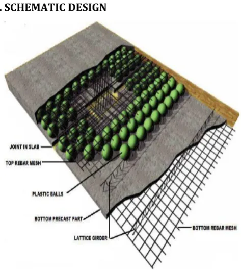
3. SCHEMATIC DESIGN
Fig -1: Cut-through Section of Bubble Deck
4. MATERIALS
Bubble Deck is composed of three main materials- reinforcement steel, plastic spheres and concrete.
4.1 Reinforcement Steel
High grade steel of Fe 550 or Fe 500 is generally used. Top and bottom steel reinforcement used with same grade of steel . Here 10mm diameter steel bar is used for main reinforcement and 8mm diameter steel bar is used for distributor reinforcement. Reinforcement provided in both transverse and longitudinal direction in the form of mesh. 4.2 Concrete
Standard Portland cement is commonly used. No plasticizer is used. On the basis of grade used, design mix procedure takes place. Common concrete or Self compacting concrete used for the precast layer . Minimum grade of concrete should not be less than M30. The depth of the slab is about 130mm.
4.3 Recycled Balls
[image:2.595.318.555.99.364.2]© 2017, IRJET | Impact Factor value: 5.181 | ISO 9001:2008 Certified Journal
| Page 1469
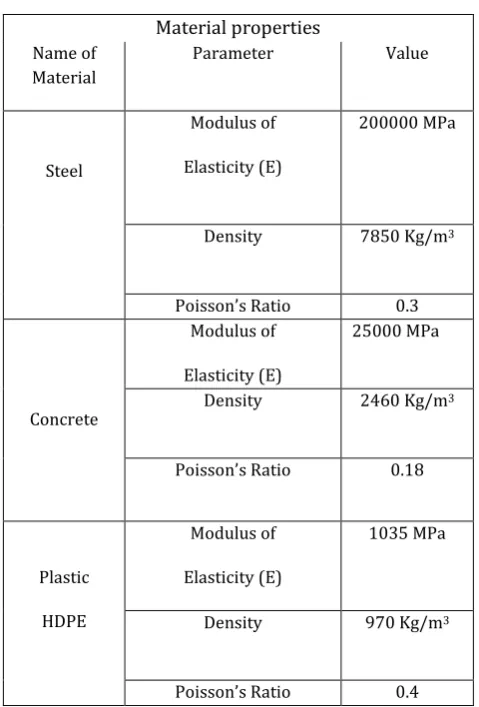
Table -1Material properties Name of
Material
Parameter Value
Steel
Modulus of
Elasticity (E)
200000 MPa
Density 7850 Kg/m3
Poisson’s Ratio 0.3
Concrete
Modulus of
Elasticity (E)
25000 MPa
Density 2460 Kg/m3
Poisson’s Ratio 0.18
Plastic
HDPE
Modulus of
Elasticity (E)
1035 MPa
Density 970 Kg/m3
Poisson’s Ratio 0.4
5. ADVANTAGES OF BUBBLE DECK
Material And Weight Reduction
The prevailing beneficial of a Bubble Deck slab is that it uses 30-50% less concrete than normal solid slabs. The HDPE bubbles replace the non-serviceable concrete
in the core of the section, thus reducing the dead load of the structure.
Decreased concrete material and weight also leads to less structural steel since the need for reinforcement diminishes.
The building foundations can be designed for smaller dead loads as well.
Overall, due to the lighter floor slabs, the several downstream components can be engineered for lower loads and thus save additional material.Structural Properties
Due to the lower dead weight of the slab and its two-way spanning action, load-bearing walls become unnecessary.
Bubble Deck is also designed as a flat slab, which eliminates the need for support beams and girder members.
As a result, these features decrease some of the structural requirements for the columns and foundations.
Additionally, Bubble Deck slabs can be designed and analyzed as a standard concrete flat slab according to research performed on its strength and ductility. Construction And Time Savings On site construction time can be shortened since Bubble Deck slabs can be precast.
This type of slab would eliminate the need for on site erection of formwork, thus significantly cutting down construction time.
Similar to modern precast concrete flooring modules, Bubble Deck can be fully shop fabricated and transported on site for installation as well.
Time savings can also be achieved through the faster erection of walls, columns and due to the lack of support beams and load bearing walls for this innovative flat slab.Cost Savings
In relation to the savings in material and time, cost reductions are also typical with the BubbleDeck system. The decreased weight and materials mean lower
transportation costs, and would by more economical to lift the components.
With less on-site construction from the full and semi-precast modules, labor costs will decrease as well. In addition, money can be saved downstream in the
design and construction of the building frame elements (columns and walls) for lower loads.
There is a slight rise in production costs for the Bubble Deck slab due to the manufacturing and assembly of the HDPE spheres.
© 2017, IRJET | Impact Factor value: 5.181 | ISO 9001:2008 Certified Journal
| Page 1470
Green Design The number of owners, designers and engineers who desire green alternatives is growing exponentially. Bubble Deck is a fitting solution for lowering the
embodied carbon in new buildings.
Accordingly 1 kg of recycled plastic replaces 100 kg of concrete.
By using less concrete, designers can save up to 40% on embodied carbon in the slab, resulting in significant savings downstream in the design of other structural members.
Carbon emissions from transportation and equipment usage will also decrease with the use of fewer materials.
Additionally, the HDPE bubbles can be salvaged andreused for other projects, or can be recycled.
Generally, for every 5,000 m2 of Bubble Deck floor slab, the owner can save:
1,000 m2 of on-site concrete and 278 tonnes of CO2
emission.
166 concrete truck trips.
1,798 tonnes of foundation load, or 19 less piles.
1,745 GJ of energy used in concrete production andtransportation.
6. STRUCTURAL PROPERTIES AND DESIGN
A number of researches have been performed at various institutions in Denmark, Germany and India etc. on the mechanical and structural behavior of Voided slab. These Studies include bending strength, deflection, shear strength, punching shear, fire resistance, and sound testing.
This paper moreover focuses on stiffness and shear resistance. Here all of the available research on Bubble Deck is based on ACI 318-11.
6.1 Bending Stiffness and Deflection
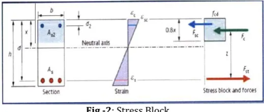
We all know that Only the top compressive portion, the "stress block", and the bottom reinforcement steel of a concrete slab contribute to its flexural stiffness in bending. Bubble Deck removes the ineffective concrete from the center of a flexural slab and replaces it with hollow HDPE spheres. The slab is designed in accordance with ACI 318-11 so that the bubble zone is placed between concrete layers of approximately of the same stress block depth as in the case of solid slab. If the slab goes with high stresses, the stress block may enter to the bubble zone. However, previous analysis has shown that anything up to a 20% intrusion has a inconsequential effect on the performance of the Bubble Deck.
Fig -2: Stress Block
One the basis of approved research the results verified with the theoretical analysis and with the physical tests . On account of same strength, Bubble Deck has 87% of the bending stiffness to that of similar solid slab but having only 66% of the concrete volume due to the area occupied by the HDPE balls.
As a result, deflection was slightly higher than that of a solid slab. However, the significant decrease in dead weight of solid slab compensated with the slightly reduced stiffness and therefore provides Bubble Deck a higher carrying capacity.
6.2 Shear strength
Due to the introduction of hollow HDPE bubbles, the shear resistance of a Bubble Deck slab is greatly reduced compared to a solid slab.
As we all know that Shear strength of any concrete slab is mainly dependent on the effective mass of concrete. From theoretical studies the shear strength of the voided slab was determined to be 60-80% of a solid slab having same depth. Hence, a reduction factor of 0.6 is needed to be applied to the shear capacity of all Bubble Deck slabs. During design of solid slabs shear is also a major concern for which several groups have performed tests on the shear capacity of Bubble Deck slabs in various situations.
In case of all flat plate systems, the floor to column connection is a area of high shear. Hence it become necessary for the designer to first determine whether the applied shear is greater or less than the shear capacity of the Bubble Deck. If shear is less, no further checks are needed. if it is greater, the designer shall remove the balls surrounding near the column and then check the shear in the newly solid section. Then If the shear resistance of the solid concrete portion is below the applied, shear reinforcement is then required ultimately.
[image:4.595.308.568.113.223.2]© 2017, IRJET | Impact Factor value: 5.181 | ISO 9001:2008 Certified Journal
| Page 1471
6.3 Punching Shear
Due to the localized forces the failure at extreme condition is associated with the term of Punching Shear or Hogging Phenomenon. As a highly concentrated reaction comes from the column onto the slab this become a common concern for flat plate floor systems.
Approved research verified that the crack pattern was similar to that of a solid slab. The punching shear was 90% of the same solid slab and local punching failure did not occur within the given load cases.
7. APPLICATION TO PEDESTRIAN BRIDGE DECKS
From the previous investigation it was clear that the shear capacity of a Bubble Deck slab is significantly less than a solid slab hence a pedestrian bridge was chosen over a vehicular bridge.
As clearly seen from current study the design of Bubble Deck cannot economically accommodate high shear resistance hence the type of loading that bridge decks experiences is a major design requirement.
Punching shear is another significant concern for a bridge deck filled with HDPE bubbles.
In the way of floor slabs, if the shear forces are too high near a column, spheres may be remove out and that area filled with solid concrete. But this is not possible in this case beacuse the high loads are constantly varying on deck slab based on time and position, so that the shear resistance needed to be great enough to support this movement. The wheels of a vehicle are point loads that travel along the deck at varying speeds and locations instead of being stationary, distributed loads as in a building. Therefore, the current structural design of a Bubble Deck slab is most likely inadequate for vehicular bridges.
However, this new floor system may be applicable for pedestrian bridges due to the lower live loads and minimized shear forces.
8. CONCLUSIONS
This paper presented a brief overall review on the conventional slab suitability and bubble deck slab suitability at different places as a different component (office slab , bridge deck slab etc.).
Office slab test provides the results of prior research, proving that the Bubble Deck slab performed better than a traditional solid concrete, biaxial slab. The maximum stresses and internal forces in the voided deck about to 40% less than the solid slab due to the decreased dead load from the use of HDPE spheres in place of concrete.
The deflection of the Bubble Deck slab was slightly higher but the stiffness decreased due to the presence of the bubbles but this situation will be overcome by the reduced
overall stress in the slab. This paper demonstrate that this type of biaxial deck will give better results under long-term and a more durable floor slab under a dominant gravity and uniform load.
This detailed investigation has proven that the Bubble Deck concept is more efficient than a conventional concrete slab in all aspects. The finite element analysis of models of the slabs also verified the prior analysis and experiments.
Upon the brief study of the bridge deck slab shows that it don’t follows the office slab of the models which was created with the same general parameters.
However, the performance of the voided slab is not recommendable in a pedestrian bridge deck. So it requires further studies on a variety of bridge layouts to fully determine the feasibility of bubble deck slab in a bridge deck.
9. ACKNOWLEDGEMENT
We wish to express our sincere gratitude to our H.O.D. Mr. Jishan Raza khan (Civil Engineering Department, Integral University, Lucknow) for providing the facilities to carry out the project work.
We are also thankful to all staff members of Civil Department, without whom the completion of this report would have been impossible.
This entire journey would not have been possible without the efforts put in by our guides, Mr. Manoj Kumar. He has been a constant source of encouragement and guidance through the entire semester.
This acknowledgment would indeed be incomplete without rendering our sincere gratitude to our family. They have always been a pillar of strength and support in our past and current endeavors.
10. REFERENCES
[1] M.Surendar et. al.“Numerical and Experimental Study
on Bubble Deck Slab” Department of Civil Engineering,Dr. Mahalingam College of Engineering and technology, Coimbatore, India (2016)
[2] L. V. HAI et. al. “The experimental analysis of bubble
deck slab using Modified elliptical balls” Department of Civil and Environmental Engineering, National University of Singapore, Singapor (2012)
[3] Neeraj Tiwari et. al. “Behaviour of Bubble Deck Slabs
and Its Application” Madan Mohan Malviya University of Technology, Gorakhpur (2000)
[4] Mrinank Pandey et. al.“Analysis of Bubble Deck Slab
Design by Finite Element Method” Department of Civil Engineering Madan Mohan Malaviya University of Technology, Gorakhpur (2014)
[5] Rinku John et. al. “A study on behaviour of bubble deck
© 2017, IRJET | Impact Factor value: 5.181 | ISO 9001:2008 Certified Journal
| Page 1472
[6] Reshma Mathew et. al. “Shear Strength Development of
Bubble deck Slab Using GFRP Stirrups” IOSR Journal of Mechanical and Civil Engineering (IOSR-JMCE) e-ISSN: 2278-1684,p-ISSN: 2320-334X, PP 01-06) (2006)
[7] Bhagyashri G. Bhade et. al. “An Experimental Study On
Two Way Bubble Deck Slab With Spherical Hollow Balls” International Journal of Recent Scientific Research Vol. 7, Issue, 6, pp. 11621-11626, June, 2016
[8] Saifee Bhagat et. al. “Parametric Study of R.C.C Voided
and Solid Flat Plate Slab” IOSR Journal of Mechanical and Civil Engineering (IOSR-JMCE) (2014)
[9] Tina Lai et. al. “Structural Behaviour of Bubble Deck
Slabs And Their Application to Lightweight Bridge Decks” (IJISET - International Journal of Innovative Science, Engineering & Technology, Vol. 1 Issue 25, November 2012 )
[10] Arati shetkara et. al. “An Experimental Study On Bubble
Deck Slab System With Elliptical Balls” (Indian J.Sci.Res. 12(1):021-027, 2015)
[11] Subramanian K et. al. “Finite Element Analysis of Voided
Slab with High Density Polypropylene Void Formers” (International Journal of ChemTech Research CODEN (USA): IJCRGG ISSN: 0974- 4290) (2014)
[12] Dr. lng. Ralf Avak et. al. (2001) “Bubble Deck-a New
Type of Hollow-Body Ceiling” Institute of Concrete, Denmark, 2001, pp. 6-9.
[13] Joo-Hong Chung et. al “An Experimental Study for Bond
Characteristics of Deformed Bar” Journal of the Korea Concrete Institute Vol. 25 . (2013)
[14] Seocho-dong et. al. “New Eco-friendly Two-way Void
Slab” TVS Forum co., Ltd., 1511-12, Seoul, Korea, 137-871 (2012)
[15] S.M Barelikar et. al. “AN Experimental Study on Two
Way Bubble Deck SLAB With Spherical Hollow Balls” (IJISET - International Journal of Innovative Science, Engineering & Technology) (2015)
[16] Amer M. Ibrahim et. al. “Bubble Deck Slab vs.
Conventional Slab” International Journal of Recent Scientific Research Research Vol. 7, Issue, 6, pp. 11621-11626 (2006)
[17] Nawir Rasidi et. al. “Crack Width Prediction in Precast
Deck Slab Concrete Structure” (International Journal of Engineering and Technology Volume 3 No. 1, January, 2013 ISSN: 2049-3444 IJET Publications )
[18] Park et. al. “Reinforced Concrete Members with Cyclic
Loading” Journal of the Structural Division, Proceeding of the ASCE, vol. 98, no. ST7 (1972)
[19] Ajdukiewicz A. et al. “Experimental study on
effectiveness of interaction between pretensioned hollow core slabs and concrete topping” ACCE, No. 1, (2008)
[20] Girhammar U.A et. al. “Tests and analysis on shear
strength of composite slabs of hollow core units and concrete topping” Malaysian JCE, Vol. 22, (2008)
[21] Kim et. al. “Performance of bridge deck link slab
designed with ductile engineered cementations composite” (ACI Structure Journal. 101(6), 792–801) (2004).
[22] Martina Schnellen et. al. “Punching behaviour of biaxial
hollow slabs" Cement and Concrete Composites” (Volume 24,Issue 6, Pages 551-556, December 2002 )
[23] Izni Syahrizal Ibrahim et. al. “Shear capacity of
composite slab reinforced with steel fiber concrete topping” Malaysian Journal of Civil Engineering 23(1) :1-23 (2011)
[24] Boskey Vishal Bahoria et. al. “Analysis and Design of RCC
and Post-tensioned Flat Slabs Considering Seismic Effect” IACSIT International Journal of Engineering and Technology, Vol. 5, No. 1, February 2013
[25] Vidya Jose et. al. “Hollow Core Slabs in Construction
Industry” International Conference On Innovations & Advances In Science, Engineering And Technology ISSN (Online) : 2319 – 8753 (2014)
[26] P.C.J. Hoogenboom et. al. “Analysis of hollow-core slab
floors” University of Technology, Faculty of Civil Engineering and Geosciences, Delft, The Netherlands (2013)
[27] S.suriya prakash et. al.“Performance of prestressed