© 2017, IRJET | Impact Factor value: 6.171 | ISO 9001:2008 Certified Journal
| Page 1775
A Concept of Using Local Materials in Road Construction
Anjani Kumar Shukla
1, Shivam Singh Patel
21
M-Tech Scholar in Maharishi University of Information Technology, Lucknow
2
Asst. Professor, High way Engineering in Maharishi University of Information Technology, Lucknow.
---***---Abstract -- Roads are the backbone for the development ofany country. Now days good quality of roads like Expressway, National highway, state highway etc has been constructing in our country. These networks of roads are providing speed in development. Nowadays new technologies has been developed and implemented for construction of good quality of roads. To construct the best quality of roads the knowledge of advance construction materials are very essential for highway engineers. The knowledge of local available highway construction materials are very essential for highway engineer to achieve economy in construction of roads. In this presentation it is being focused on the local available material (silt) using for the construction of road and try to achieve economy in construction of road by the mixing of silt with stone dust in granular sub base with keeping in mind and also without compromising in quality and characteristics of road. Million tons of silt removed from canals and rivers every year is almost useless. I have utilized these material (canal silt) for the construction of road. Utilization of canal silt reduces the construction cost of road as well as it protect the environment also.
INTRODUCTION –
Government of India considers road network as critical to the country development,social integration and security needs. The national highways are the backbone of the road infrastructure and the major roads in the country. They carries India’s most freight and passengers traffic. State highways and major district roads constitutes the secondary and inter connecting roads in India. Pradhan Mantry Gram Sarak Yojna roads are developing our rural areas road network. There are four major modes of transport i.e. Highways, Railways, Waterways, Airways.
Construction of road pavement, its drainage system, development, planning, alignment, geometric design, highway traffic operation and its control, pavement design, construction and maintenance materials, economic consideration finance and admin systems are deals within the highway engineering. Indian Road Congress has divided the roads in different categories like village road, Major district road ,Other district road, State highway, National highway and express way. IRC –SP 72 Clause 5.2 presents the guidelines for construction of roads with locally available materials like selected granular soil for
sub grade, stabilization of local soil, bricks and over burnt brick metal, industrial waste, stone metal, naturally occurring softer metals like kankar, mooram etc.
Sub grade Soil Strength-- The soil sub grade is the layer of natural soil prepared to receive the layer of pavement materials placed over it. The loads of the pavement are ultimately received by the soil sub grade for dispersion to earth mass. It is essential that at no time soil sub grade overstressed i.e. pressure transmitted to the top of the sub grade is within the allowable limit. It is necessary to evaluate the strength properties of the soil sub grade. Therefore the sub grade soil should have proper strength to resist the load coming on it. Factor on which the strength characteristic of soil depends are:
Soil type
Moisture Content Dry density
Internal structure of soil
Type and mode of stress application
Evaluation of Soil Strength-- Strength of soil may be evaluated by following three methods Shear tests, Bearing test, Penetration tests, Shear Tests are carried out in laboratory by small soil samples in laboratory. Some commonly known shear tests are Direct shear tests, Tri axial compression shear test and Unconfined compression tests. Vane shear tests may be carried out either on a soil sample or in situ soil in the field.
Bearing Test-- These are loading tests carried out on sub grade soil in situ with a load bearing . The results of the bearing tests are influenced by the variations of the soil properties within the soil mass underneath.
© 2017, IRJET | Impact Factor value: 6.171 | ISO 9001:2008 Certified Journal
| Page 1776
TABLE Standard Load Values on crushed stone for different penetration values by CBR TestPenetration
mm Standard load Kg Unit standard load kg/cm2
2.5 1370 70
5.0 2055 105
7.5 2630 134
10.0 3180 162
12.5 3600 183
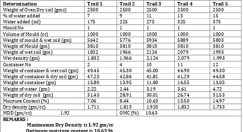
TABLE:- TestReport of soil for maximum dry density & optimum moisture content ( as per is 2720 part -8 )
Determination Trail 1 Trail 2 Trail 3 Trail 4 Trail 5
Weight of Oven Dry soil (gms) 2500 2500 2500 2500 2500
% of water added 7 9 11 13 15
Water added (ml) 175 225 275 325 375
Mould No 1 1 1 1 1
Volume of Mould (cc) 1000 1000 1000 1000 1000
Weight of mould & wet soil (gm) 5642 5776 5934 5889 5803
Weight of Mould (gm) 3810 3810 3810 3810 3810
Weight of wet soil (gm) 1832 1966 2124 2079 1993
Wet density (gm) 1.832 1.966 2.124 2.079 1.993
Container No 2 4 10 11 12
Weight of container & wet soil (gm) 49.45 45.30 45.00 44.90 49.30 Weight of container & dry soil (gm) 47.23 42.86 41.81 41.29 44.58
Weight of container (gm) 15.80 13.95 11.80 14.55 13.05
Weight of water (gm) 2.22 2.44 3.19 3.61 4.72
Weight of dry soil (gm) 31.43 28.91 30.01 26.74 31.53
Moisture Content (%) 7.06 8.44 10.63 13.50 14.97
Dry density (gm/cc) 1.711 1.813 1.920 1.832 1.733
MDD (gm/cc) 1.92 OMC (%) 10.63 REMARKS :
Maximumm Dry Density is 1.92 gm/cc Optimum moisture content is 10.63 %
STONE AGGREGATES ---
Stone aggregates are the main and prime material use in construction of pavement. Major portion of pavement structure are constructed by stone aggregates. Most of the road aggregates are prepared by crushing of natural rocks like igneous, sedimentary and metamorphic. The properties of aggregates are very important for us.
DESIRABLE PROPERTIES OF ROAD AGGREGATE –
The desirable properties of the aggregates may be summarized as follows:-
Resistance to crushing of strength Resistance to abrasion or hardness Resistance to impact or toughness Resistance to weathering or soundness
Good shape factors to avoid too flaky and elongated particles of course aggregates
Good adhesion with bituminous materials in presence of water or less stripping.
Following are the main points considerable for road aggregates:
Strength:-
Aggregates used in top layers are subjected to stress action due to traffic wheel loads.
© 2017, IRJET | Impact Factor value: 6.171 | ISO 9001:2008 Certified Journal
| Page 1777
Hardness:-The aggregate use in surface course aresubjected to constant rubbing or abrasion due to moving traffic. The aggregate should be hard enough to resist the abrasive action caused by the movements of traffic. The abrasive action is sever when steel tyre vehicle moves over the aggregates exposed at the top surface.
Toughness: Resistance of the aggregate to impact is termed as toughness .Aggregate used in the pavement should be able to resist the effect caused by the jumping of the steel tyres wheel from one particle to another at different levels caused severe impact on the aggregates.
Shape of aggregates: Aggregates which happen to fall in a particular size range may be rounded, cubical, angular, flaky or elongated particles. It is evident that the flaky and elongated particles will have less strength and durability when compared with cubical, angular or rounded particles of the same aggregates. Hence to flaky and too much elongated aggregate should be avoided as for as possible.
Adhesion with bitumen:-The aggregates use in bituminous pavements should have less affinity with water when compared with bituminous materials ,otherwise the bituminous coating on the aggregates will be stripped off in presence of water.
Durability:-The property of aggregates to withstand adverse action of weather is called soundness. The aggregates are subjected to the physical and chemical action of rain and bottom water, impurities therein and that of atmosphere, hence it is desirable that the road aggregates used in construction should be sound enough to withstand the weathering action.
[image:3.595.55.547.391.537.2]Freedom from deleterious particles:-Specifications for aggregates used in bituminous mixture usually required the aggregates to be clean tough, and durable in nature and free from excess amount of flat or elongated pieces ,dust clay balls and other objectionable materials. Simlarlly aggregate used in Portland cement concrete mixes may be clean and free from deleterious substances such as clay lumps, chert, silts and other organic impurities.
TABLE:- Physical Requirement of course aggregate as per IS Codes
Sl.no Type of construction Test for WBM Test Methods Requirements
1 Sub base Loss Angles Abrasion
Value of aggregate Impact value
IS 2386 (Pt.IV) IS 2386(Pt IV) IS 5640ᶲᶲᶲ
60% Max ᶲ50% Max
2 Base course (a) Loss Angles Abrasion Value of aggregate Impact value (b)Flakiness Index
IS 2386 (Pt.IV) IS 2386(Pt IV) IS 5640ᶲᶲᶲ IS 2386(Pt. I)
50% Max ᶲ40% Max
ᶲᶲ15% Max 3 Surface course (a)Loss Angles Abrasion Vlue or
Aggregate Impact value (b)Flakiness Index
IS 2386 (Pt.IV) IS 2386(Pt IV) IS 2386(Pt. I)
40%Max 30%Max ᶲᶲ15%Max ᶲ Aggregates may satisfy requirements are either of the rwo tests
ᶲᶲThe requirement of flakiness test index test shall be enforced only in case of crushed/broken stone and crushed slag
ᶲᶲᶲAggregate like brick metals,kankar and laterite which get softened in presence of water,shall be tested for impact value under wet conditions in accordance with IS 5640
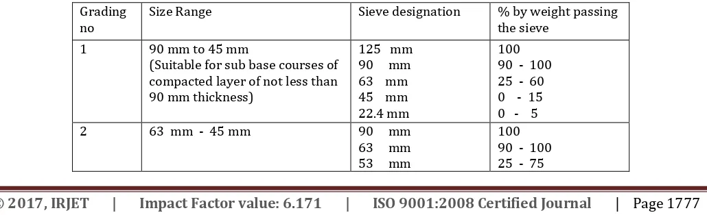
TABLE :- GRADING REQUIREMENT OF COURSE AGGREGATES FOR WBM:-AS PER CPWD SPECIFICATIO
Grading
no Size Range Sieve designation % by weight passing the sieve
1 90 mm to 45 mm
(Suitable for sub base courses of compacted layer of not less than 90 mm thickness)
125 mm 90 mm 63 mm 45 mm 22.4 mm
100 90 - 100 25 - 60 0 - 15 0 - 5
2 63 mm - 45 mm 90 mm
63 mm 53 mm
[image:3.595.42.557.628.785.2]© 2017, IRJET | Impact Factor value: 6.171 | ISO 9001:2008 Certified Journal
| Page 1778
45 mm
22.4 mm 0 - 15 0 - 5
3 53 mm - 22.4 mm 63 mm
53 mm 45 mm 22.4 mm 11.2 mm
100 95 - 100 65 - 90 0 - 10 0 - 5
TABLE :- GRADING FOR SCREENINGS AS PER CPWD SPECIFICATION
Grading
classification Size of screeners Sieve designation % by weight passing sieve
A 13.2 mm 13.2 mm
11.2 mm 5.6 mm 180 microns
100 95 -100 15-35 0 -10
B 11.2 mm 11.2 mm
5.6 mm 180 microns
[image:4.595.69.527.357.508.2]100 90 – 100 15 - 35
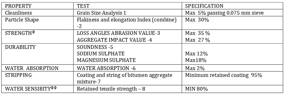
TABLE :- PHYSICAL REQUIREMENT OF COURSE AGGREGATE FOR DENSE BITUMINOUS MACADAM
PROPERTY TEST SPECIFICATION
Cleanliness Grain Size Analysis 1 Max 5% passing 0.075 mm sieve
Particle Shape Flakiness and elongation Index (combine)
-2 Max 30%
STRENGTHᶲ LOSS ANGLES ABRASION VALUE-3
AGGREGATE IMPACT VALUE -4 Max 35 % Max 27 %
DURABILITY SOUNDNESS -5
SODIUM SULPHATE
MAGNESIUM SULPHATE Max 12% Max18%
WATER ABSORPTION WATER ABSORPTION -6 Max 2%
STRIPPING Coating and string of bitumen aggregate
mixture-7 Minimum retained coating 95%
WATER SENSIBITYᶲᶲ Retained tensile strength – 8 MIN 80%
TABLE :- LIMITS OF CONTENT OF ORGANIC AND THE DELETERIOUS MATERIALS AS PER IS 2386(Pt-ii)
MATERIALS UNCRUSHED CRUSHED
Coal and lignite 1% 1%
Clay lumps 1% 1%
Material Passing through
75 micron( ISS) sieve 3% 3%
Shale 1% 1%
The sum of all the percentage of deleterious material should not exceed 5%.
TABLE :- PHYSICAL REQUIREMENT OF AGGREGATES FOR SURFACE DRESSING
SL.NO TEST TEST METHOD REQUIREMENT
1 Los Angles Abrasion
Value IS 2386(Pt -iv) 40% Max
2 Aggregate Impact
© 2017, IRJET | Impact Factor value: 6.171 | ISO 9001:2008 Certified Journal
| Page 1779
3 Flakiness Index IS 2386 (Pt-1) 25% Max
4 Stripping value IS 6241 25% Max
5 Water absorption IS 2386 (Pt iii) 1% Max
[image:5.595.56.532.208.612.2]Aggregate may satisfy requirements of either of two ests.
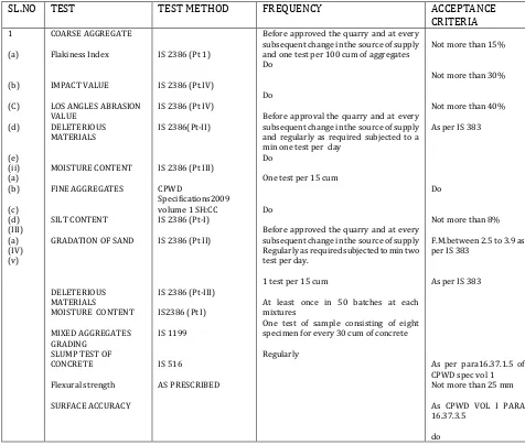
TABLE :- MATERIALS USED FOR ROAD WORK,QUALITY CONTROL, ACCEPTANCE CRITERIA ACCORDIND TO CODE AND CPWD
SL.NO TEST TEST METHOD FREQUENCY ACCEPTANCE
CRITERIA
1
(a)
(b)
(C)
(d)
(e) (ii) (a) (b)
(c) (d) (III) (a) (IV) (v)
COARSE AGGREGATE
Flakiness Index
IMPACT VALUE
LOS ANGLES ABRASION VALUE
DELETERIOUS MATERIALS
MOISTURE CONTENT
FINE AGGREGATES
SILT CONTENT
GRADATION OF SAND
DELETERIOUS MATERIALS
MOISTURE CONTENT
MIXED AGGREGATES GRADING
SLUMP TEST OF CONCRETE
Flexural strength
SURFACE ACCURACY
IS 2386 (Pt 1)
IS 2386 (Pt.IV)
IS 2386 (Pt IV)
IS 2386(Pt-II)
IS 2386 (Pt III)
CPWD
Specifications2009 volume 1 SH:CC IS 2386 (Pt-I)
IS 2386 (Pt II)
IS 2386 (Pt-III)
IS2386 (Pt I)
IS 1199
IS 516
AS PRESCRIBED
Before approved the quarry and at every subsequent change in the source of supply and one test per 100 cum of aggregates Do
Do
Before approval the quarry and at every subsequent change in the source of supply and regularly as required subjected to a min one test per day
Do
One test per 15 cum
Do
Before approved the quarry and at every subsequent change in the source of supply Regularly as required subjected to min two test per day.
1 test per 15 cum
At least once in 50 batches at each mixtures
One test of sample consisting of eight specimen for every 30 cum of concrete
Regularly
Not more than 15%
Not more than 30%
Not more than 40%
As per IS 383
Do
Not more than 8%
F.M.between 2.5 to 3.9 as per IS 383
As per IS 383
As per para16.37.1.5 of CPWD spec vol 1 Not more than 25 mm
As CPWD VOL I PARA 16.37.3.5
do
SPECIFICATION OF MATERIALS AS PER MORTH : -
The materials to be used for road work shall be natural sand crushed gravel, crushed stone, crushed slag or combination thereof depending upon the grading required. The materials should be free from organic or other
© 2017, IRJET | Impact Factor value: 6.171 | ISO 9001:2008 Certified Journal
| Page 1780
TABLE :- Grading of Granular Sub Base materials ( MORTH TABLE NO.400-I )IS EIVE
DESIGNATION
PERCENT BY WEIGHT PASSING THE IS SIEVE
Grading i
Grading ii Grading
iii
Grading
iv
Grading v Grading
vi
75.0 mm 100 - - - 100 -
53.0 mm 80-100 100 100 100 80-100 100
26.5 mm 55-90 70-100 55-75 50-80 55-90 75-80
9.50 mm 35-65 50-80 - - 35-65 55-75
4.75 mm 25-55 40-65 10-30 15-35 25-50 30-55
2.36 mm 20-40 30-50 - - 10-20 10-25
0.85 mm - - - - 2 - 10 -
0.425 mm 10-15 10-15 - - 0-5 0 - 8
0.075 mm < 5 < 5 < 5 < 5 - 0 - 3
TABLE:- PHYSICAL REQUIREMENT OF MATERIALS FOR GRANULAR SUB BASE( MORTH TABLE NO.400-2)
Aggregate Impact Value (AIV) IS 2386 PART IV or size 5640 40 Maximum
Liquide Limit IS 2720 (Part -5) 25 Maximum
Plastycity Index IS 2720 (Part -5) 6 Maximum
CBR at 98% dry density(at IS2720-Part 8)
IS 2720 (Part -5) Minimum 35 unless otherwise specified in the contract
Specification of Materials Utilized for This Thesis Work
All the materials for construction of roads are traditional except material used in Granular Sub Base .In Granular Sub Base also all the materials used are same as
discussed above but we are using locally available good quality of silt for Granular Sub Base layer.All the materials and its qualities has already been discussed in previous chapters. Laboratory test reports of Materials are attached herewith:
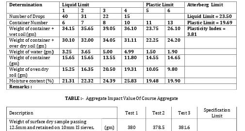
TABLE NO: - ATTERBERG LIMIT OF SOIL ( As per IS 2720 Part -5 )
Determination Liquid Limit Plastic Limit Atterberg Limit
1 2 3 4 5 6
Number of Drops 40 31 22 15 Liquid Limit = 23.50
Container Number 6 7 8 10 11 13 Plastic Limit = 19.69
Weight of container +
wet soil (gm) 34.15 35.65 39.05 36.10 23.75 26.10 Plasticity Index = 3.81 Weight of container +
over dry soil (gm) 30.10 32.00 34.05 31.11 22.25 24.20
Weight of water (gm) 3.25 3.65 5.00 4.99 1.50 1.90
Weight of container
(gm) 15.65 15.65 13.55 11.80 14.55 14.65
Weight of oven dry
soil (gm) 15.25 16.35 20.50 19.31 10.05 9.80
[image:6.595.47.552.478.748.2]Moisture content (%) 21.31 22.32 24.39 25.83 19.48 19.90 Remarks :
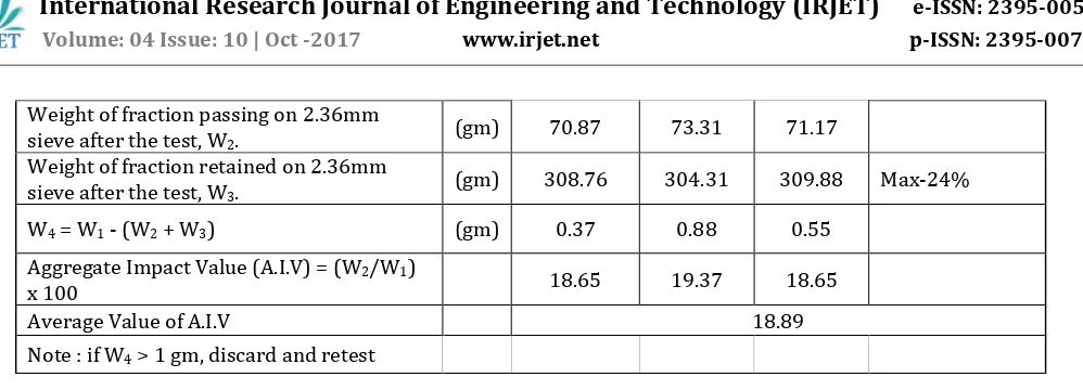
TABLE :- Aggregate Impact Value Of Course Aggregate
Description Test 1 Test 2 Test 3 Specification Limit
Weight of surface dry sample passing 12.5mm and retained on 10mm IS sieves, W1.
© 2017, IRJET | Impact Factor value: 6.171 | ISO 9001:2008 Certified Journal
| Page 1781
Weight of fraction passing on 2.36mm
sieve after the test, W2. (gm) 70.87 73.31 71.17
Weight of fraction retained on 2.36mm
sieve after the test, W3. (gm) 308.76 304.31 309.88 Max-24%
W4 = W1 - (W2 + W3) (gm) 0.37 0.88 0.55
Aggregate Impact Value (A.I.V) = (W2/W1)
x 100 18.65 19.37 18.65
Average Value of A.I.V 18.89
[image:7.595.53.552.53.233.2]Note : if W4 > 1 gm, discard and retest
TABLE : - CALIFORNIA BEARING RATIO( CBR) TEST OF SOIL (AS PER 2720 PART 16 )
Sample Material : Soil Date of Casting / soaking : 02/08/17 Static/ Dynamic : Dynamic Date of Testing : 06/08/17 Volume of Mould : 2209 cm3 Soaking Period : 96 hrs. Capacity of Proving Ring : 50 KN Calibration Factor , 1 Div : 6.21 Area of Plunger : 19.635 Cm2 OMC (%) : 10.63 MDD (gm/cc) : 1.92
SL NO Item` Moulds before soaking Moulds after soaking
1 Weight of mould + wet soil
(W1 gm ) 11872 11852 11825 11921 11911 11854
2 Weight of mould (W2 gm) 7260 7260 7200 7260 7260 7200
3 Weight of wet soil ( W3 =
W1-W2) gms 4612 4592 4625 4661 4651 4654
4 Bulk Density of soil = W3 /V
(gm/cc) 2.088 2.079 2.094 2.110 2.105 2.107
5 Container No 7 8 9 10 11 12
6 Weight of Container = w1 (gm) 15.65 13.55 13.20 11.80 14.55 13.05 7 Weight of Container + wet soil
= w2 (gm) 51.23 52.34 55.26 51.24 53.56 55.32
8 Weight of Container + oven
Dry soil =w3(gm) 47.99 48.81 51.42 47.59 50.17 51.43
9 Weight of dry soil w = w3- w1
(gm) 32.34 35.26 38.22 35.79 33.58 38.38
10 Weight of water w’=w2-w3 3.24 3.53 3.84 3.65 3.39 3.89
11 Water Content (%) =w’/w*100 10.02 10.01 10.05 10.20 10.10 10.14
12 Dry Density (gm/cc) 1.898 1.89 1.903 1.915 1.912 1.913
LOAD
Penetr ation (mm)
Mould 1 Mould 2 Mould 3 Avg
CBR Provi
ng Ring Readi ng
Load Load kg/c m2
CBR
% Proving Ring Readi ng
Load Load kg/c m2
CB R %
Provi ng Ring Readi ng
Load Loa d kg/c m2
CB R %
0.00 0 0 0 0 0 0 0 0 0
0.50 3 18.63 0.95 3.00 18.63 0.95 4.00 24.84 1.27
1.00 7 43.47 2.21 7.00 43.47 2.21 8.00 49.68 2.53
1.50 13 80.73 4.11 12.00 74.52 3.80 13.00 80.73 4.11
2.00 17 105.57 5.38 18.00 111.7
8 5.69 19.00 117.99 6.01
© 2017, IRJET | Impact Factor value: 6.171 | ISO 9001:2008 Certified Journal
| Page 1782
9 2 4 5 30
3.00 27 167.67 8.54 25.00 155.2
5 7.91 30.00 186.30 9.49
4.00 37 229.77 11.7
0 35.00 217.35 11.07 40.00 248.40 12.65
5.00 47 291.87 14.8
6 14.16 45.00 279.45 14.23 13.55 54.00 335.34 17.08 16.27 14.66
7.50 75 465.75 23.7
2 72.00 447.12 22.77 79.00 490.59 24.99
10.00 101 627.21 31.9
4 97.00 602.37 30.68 110.00 683.19 34.79
12.50 134 832.14 42.3
8 127.00 788.67 40.17 131.00 813.51 41.43 Avg CBR at 2.5mm Penetration =10.54 %
Avg CBR at 2.5mm Penetration =14.66 %
From the above test results we see that all the materials are good quality and within the limit of MORTH
standard.
Materials Consumptions for one KM of road using locally abailable material (canal silt) :-
All the materials consumptions has discussed in articles. In Granular Sub Base we are using locally available good quality of silt with stone dust in appropriate ratio. Calculation of materials are as follows Close Graded Sub Base material as per table 400-1 For grading 1 material. For taking out 225 Cum (450 MT)
53 mm to 9.5 mm @ 50 % 144 Cum
9.5 mm to 2.36 mm @ 20 % 57 Cum
2.36 mm below @ 30 % of 86.400 Cum. For thesis purpose 2.36 mm below @ 55 % stone dust of 86.40 cum ie 47.52 Cum
Good quality of silt collected from canals 45% of 86.40 cum 38.88 Cum
Water as per I.D.S.O.R 27.00 Cum
The cost of Granular Sub Base Course As per MORTH specification including labors , machineries, materials and laying with compaction comes Per Cum Rs 3619.95.
While For construction of road all the specifications are same as above but in Granular Sub Base layer as per MORTH specification 30% 2.36 mm below stone dust was used but now in this item we have mixed stone dust and silt in the ratio of 55% and 45% respectively. In the analysis of rate we can see that the cost of Granular Sub
Base course including labors ,machineries, materials and laying with compaction comes Rs 3278.20 per Cum
Conclusion:-
The construction cost of road has became very high nowadays. By using canal silt in partially replacement of 2.36 mm below stone dust in Granular Sub Base layer for construction of road we can achieve economical construction of road without compromising the quality of road .Canal or river silt is very economical as well as environment friendly also.
The result obtained for the advance construction materials are good and they are satisfying the standard uses for road construction like IS Codes, MORTH and CPWD Specifications also.
As per MORTH specification the cost of Granular Sub Base Course including labors , machineries, materials and laying with compaction comes Per Cum Rs 3619.95.
For construction of road all the specifications are same but in Granular Sub Base layer as per MORTH specification 30% 2.36 mm below stone dust was used but now in this item we have mixed stone dust and silt in the ratio of 55% and 45% respectively. In the analysis of rate we can see that the cost of Granular Sub Base course including labors ,machineries, materials and laying with compaction comes Rs 3278.20 per Cum.
© 2017, IRJET | Impact Factor value: 6.171 | ISO 9001:2008 Certified Journal
| Page 1783
With the abstract of cost it is clear that the cost of one Km road by using traditional material comes Rs 489.27 lacs per Km and when we used (stone dust 55% and canal silt45%) the cost of one Km of same road comes Rs 478.50 lacs per Km. Thus Rs 10.77 lacs are saving per Km. ie if we construct road 100 Km we can save Rs ten crores seventy seven lacs and if we consider in the reference of construction of road 1000 Km then we are saving Rs more than one hundred seven crores i.e. we are saving very huge amount.
Thus we can save large amount in the construction of road with the application of using available local materials without compromising with the quality of road.
Further if we interlink the construction of road with the de silting of canal it will provide economy in two ways. (1)The construction cost of the road is reducing considerably. (2)The few part of the expenditure cost of de silting will get back by selling the silt excavated from canal bed to the agency which is carried out for the construction of the road.