© 2018, IRJET | Impact Factor value: 6.171 | ISO 9001:2008 Certified Journal | Page 2526
Design and Performance evaluation of Wheat Crop Cutting Machine
Mohd. Shahid Hayat
1, P. N. Shende
2, P. H. Narnaware
31
Student of M-Tech Production, YCCE, Maharashtra, India
2Professor of Mechanical Department, YCCE, Maharashtra, India
3Professor of Applied Chemistry Department, DBACER,
Maharashtra, India
---***---Abstract -
This machine targets the small scale farmer who are not affordable the high cost machine or on the rented bases, so that the idea is to prepare a machine which work like similar operation as actual machine but in modification of their system. This work describes the constructions of a crop cutting machine. The machine consists of four main parts, name as cutter blades, slider crank mechanism, Rack and pinion, and Crop reel system. The machine run on motor of 24V DC motor, this power from motor is provided to the slider crank mechanism through cutter. A collecting mechanism are provided which bend the crops and easily allow the crop to cut, after cutting these crops fall into the rack and pinion mechanism which collect and force the crops at one side. The design of reel includes determination of the rotational speed of reel. On the basis of their design is to determine minimum grain losses. The test was conducted to study the performance of our machine for that, testing was done at farm. After the testing machine performance was evaluated on the basis of their parameter like the forward speed (km/hr) field capacity (ha/hr), field efficiency (%).Key Words: Slider Crank Mechanism, Collecting system, Performance testing
1. INTRODUCTION
The Farming is most widely followed profession in India. Agricultural products contribute a major portion to our economy. The crop cutting is important stage in agriculture field. Crop harvesting is the last stage in farming which takes maximum time of farmer among all farming process .Crop harvesting is a process of cutting the crops closed to the ground or pulling the plants when they are ripped out. It includes cutting the stems of coral crops like wheat and rice etc, closed to the ground. In our country it is done by sharp sickle. Engineering science has brought tremendous changes in traditional crop cutting methods. Farming in India is not only limited to growing of crops but is also associated with the economic growth of farmers and labor. Farmers in Vidarbha have been experiencing a problem of lack of skilled and cheap labor which has ultimately forced them to adopt the use of machine.
The status of mechanization in agriculture varies for different activities, although the overall level of mechanization is still less than 50%, as compared to 90% in developed countries.62 The highest level of mechanization (60%-70%) is observed in harvesting and threshing activities and irrigation (37%).To increase productivity, farm equipment which is durable, light-weight and low cost, and
also specific to different crops and regions should be made available for small and marginal farmers. Some challenges faced by farm mechanization include different soil and climatic zones which require customized farm machinery, and small land holdings with lack of access to resources. Mechanization should aim to increase agricultural efficiency by reducing the time and labor requirement, minimizing wastage and reducing costs of labor.
The alarming rate of growth in population has now made it necessary to fasten the rate of production of agricultural products using mechanized system. These machines are available in market for purchase or are made available on hourly basis on rent by agricultural organizations but small scale farmers do not require such full/extra featured combined harvesters. Thus there is a need for the development of a compact and a comparatively cheap machine which will be affordable to the small scale farmers. The focus of the project is to create a portable, compact and user friendly low cost and mini collector machine which will simultaneously perform both jobs of cutting and collecting the crops. This machine is cost effective, easy to maintain and can be simply manufactured as it comprises of locally available spare parts.
The low productivity in India is a result of the following factors:
Adoption of modern agricultural practices and use of technology is inadequate, hampered by ignorance of such practices, high costs and impracticality in the case of small land holdings.
Small size and scattered holdings of the farmers stand in the way of mechanization. As a result of this, farm machinery generally remains underutilized.
Majority of small cultivators are poor who are not in a position to purchase the costly machinery like tractors, combine harvesters etc.
Lack of proper knowledge of farmer to purchase farm machinery, operate and maintain it properly leads to wrong choice, makes it uneconomical and risky too.
© 2018, IRJET | Impact Factor value: 6.171 | ISO 9001:2008 Certified Journal | Page 2527
The lack of repair and replacement facilities especially in the remote rural areas is another hindrance in efficient small farm mechanization.
Illiteracy, general socio-economic backwardness, slow progress in implementing land reforms and inadequate or inefficient finance and marketing services for farm produce.
2. METHODOLOGY AND STUDY OF DIFFERENT
MECHANISM
As being stated in the statement of the problem in order to develop the machine which solve the specified problem, So that the theoretical analysis of the method applied to a study. The aim was to fabricate affordable machine with locally available parts for economy growth of farmers. To achieve this aim, it was decided following steps.
Interact with local small scale farmers to obtain a basic idea of traditional techniques used for harvesting.
Studying the present mechanisms.
Consulting agricultural machines manufacturers. To get information about different operation.
Reviewing different literature review and Gathering raw data and interpreting it.
Design of crop cutting machine Cero model.
Calculation
Performance Evaluation
Result and conclusion
2.1 Studying Different types of mechanism
Concept 1: (Single Circular Rotating Cutter)
This mechanism works on the single circular blade which is rotate in one direction. The power is directly given by shaft to bevel gear agreements to the cutter. The reason for dropping this concept because of less cutting surface area and second is crops may fall on either side of machine.
Concept 2: (Using two Circular Blades)
This mechanism of crop cutting work on the two same circular saw cutter which is rotates in opposite directions. Reason for dropping this concept, collection mechanism was absent, making the crop to fall on either sides creating problem for farmer to collect the cut crop.
Concept 3: (Scotch yoke mechanism)
It is the one of the good alternative to the above two concepts. This mechanism converts the rotating
motion to the reciprocating motion which gives the cutting active to the cutter. Reason to dropping this concept due to low transmission of cutting force, friction on rotating yoke and this mechanism may fail when the bunch of crops gathers on the reciprocating cutter. Because of this critical mechanism it may creates a problem during the cutting of crops.
2.3 Final Proposed Design
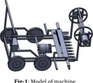
[image:2.595.358.515.344.484.2]In this concept it is a thought of making some changes in the existing machine, keeping in mind to design a machine with more effective as well as cost effective. The motor power of this machine is 250W, which transmitted to the cutter with the help of slider crank mechanism. This mechanism converts the rotary motion of disc into reciprocating motion. A cutter assembly consists of two sets of cutter one set of cutter attached with the slider crank mechanism. And another cutter is fixed with chassis. The cutters used are of straight shape. This sliding motion of cutter gives the scissoring action responsible for cutting the crops.
Fig-1: Model of machine
Collecting mechanism consist of the cylindrical section which consist of three blades, the crops are guided towards backside by means of the cylindrical collecting mechanism system. The purpose of this system to hold the crop against the cutting mechanism, to clear the cut stalks from the cutter and to deliver cut material to other units of the machine. Its effectiveness is dependent upon how closer they pass to the cutter, better the clearing of cut material and the more constant the feed rate. The optimum position of this system is determined by the crop height, amount of straw cut and condition of the straw. Note (Peripheral rotating collecting speed should be slightly faster than ground speed for good result.
3. DESIGN CALCULATION
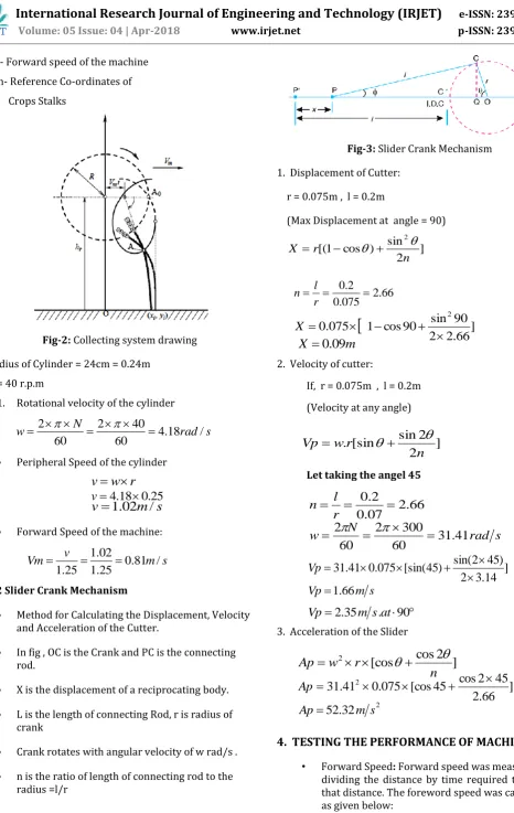
3.1 Collecting Systems Ao - Initial Position
© 2018, IRJET | Impact Factor value: 6.171 | ISO 9001:2008 Certified Journal | Page 2528 Vm - Forward speed of the machine
[image:3.595.57.524.29.767.2]Xn,Yn- Reference Co-ordinates of Crops Stalks
Fig-2: Collecting system drawing Radius of Cylinder = 24cm = 0.24m
N = 40 r.p.m
1. Rotational velocity of the cylinder
Peripheral Speed of the cylinder
Forward Speed of the machine:
3.2 Slider Crank Mechanism
Method for Calculating the Displacement, Velocity and Acceleration of the Cutter.
In fig , OC is the Crank and PC is the connecting rod.
X is the displacement of a reciprocating body.
L is the length of connecting Rod, r is radius of crank
Crank rotates with angular velocity of w rad/s .
n is the ratio of length of connecting rod to the radius =l/r
Fig-3: Slider Crank Mechanism 1. Displacement of Cutter:
r = 0.075m , l = 0.2m
(Max Displacement at angle = 90)
2. Velocity of cutter:
If, r = 0.075m , l = 0.2m
(Velocity at any angle)
Let taking the angel 45
3. Acceleration of the Slider
4. TESTING THE PERFORMANCE OF MACHINE
• Forward Speed: Forward speed was measured by dividing the distance by time required to travel that distance. The foreword speed was calculated as given below:
s
rad
N
w
4
.
18
/
60
40
2
60
2
r
w
v
25
.
0
18
.
4
v
s
m
v
1
.
02
/
s
m
v
Vm
0
.
81
/
25
.
1
02
.
1
25
.
1
]
2
sin
)
cos
1
[(
2n
r
X
66
.
2
075
.
0
2
.
0
r
l
n
]
66
.
2
2
90
sin
90
cos
1
075
.
0
2
X
m
X
0
.
09
]
2
2
sin
[sin
.
n
r
w
Vp
66
.
2
07
.
0
2
.
0
r
l
n
s
rad
N
w
31
.
41
60
300
2
60
2
]
14
.
3
2
)
45
2
sin(
)
45
[sin(
075
.
0
41
.
31
Vp
s
m
Vp
1
.
66
2
.
35
m
s
.
at
90
Vp
]
2
cos
[cos
2n
r
w
Ap
]
66
.
2
45
2
cos
45
[cos
075
.
0
41
.
31
2
Ap
2
32
.
52
m
s
[image:3.595.75.240.122.324.2]© 2018, IRJET | Impact Factor value: 6.171 | ISO 9001:2008 Certified Journal | Page 2529 Forward Speed (S) km/hr =
Where
D = distance, m T = time, s
S = forward speed
Distance = 12 ft=3.6m , Time = 40 sec
= 0.09 m/s = 0.32 km/hr
• Theoretical Field Capacity (TFC): Theoretical field capacity of machine is the rate of crop cutting that would be obtained if the machine were performing its function 100% of the time at rated forward speed and always covered 100% of its cutting width.
TFC =
Where,
S = rated forward speed, m/s
w = cutting width, m
• Effective Field Capacity or Actual Field Capacity: The effective or actual field capacity of a farm machine is defined as the actual area covered by the machine per unite time or the area covered divided by the total time is EFC.
EFC =
Time during the cutting = 62sec = 0.0172 hr Width of cutter = 2.7ft = 0.82m
Actual cutting area = Distance cover * width of cutter A= 3.6 *0.82 = 3m2 =0.0003 ha
• Field efficiency: The field efficiency was determined by the ratio of effective field capacity to the theoretical field capacity.
Field Efficiency =
Where,
EFC= Effective Field Capacity
TFC = Theoretical Field Capacity
5. RESULT AND DISCUSSION
The results about peripheral reel speed indicated that when the peripheral reel speed was increased, the losses tended to decrease initially. However, as the peripheral reel speed was increased, more losses occurring ascension ally. Very low peripheral reel speed created more losses because the fingers could not collect all the crops towards the chamber. On the other hand, when the reel speed was high or moved too quickly, the fingers would beat the head violently resulting in the greater loss
The field capacity and efficiency are very important parameter which should be taken into consideration when we evaluate machine performance. The actual field capacity is affected by many factors such as machine forward speed, height of cutter bar and crop collecting system. The data collected during field evaluation trails were analyzed to determine the forward speed (km/hr) field capacity (ha/hr), field efficiency (%),
6. CONCLUSION
An experiment was conducted to study the performance of our machine for that, testing was done at 4 different farms. After the each testing machine performance war evaluated on the basis of their parameter like field capacity, cutter design and adjusting collecting system of this machine . On the bases of result suitable modification was done and rechecking their performance. The effective cutting width of the harvester was 0.82m. The average forward speed of combine was 0.32 km/hr. Theoretical field capacity and the effective field capacity were 0.025 ha/hr. and 0.0172 ha/hr and 0.91 ha/hr respectively. The field efficiencies were 68.8% for wheat.
REFERENCES
[1] Ephrem Zeleke Kassa, Dr. Ing Zewdu Abdi, “Design and Modification of Appropriate Reel Mechanism to Harvest Tef Crop”, International Journal of Research in Mechanical Engineering Volume-2, Issue-1, January-February, 2014, pp. 15-25, © IASTER 2014. )
( ) ( T Time
D Disance
h
ha
W
S
10
hr
ha
time
Total
area
cutting
Actual
.
.
.
100
.
.
.
.
C
F
T
C
F
E
) (
) ( T Time
D Disance
S
40 6 . 3
10
81
.
0
32
.
0
hr ha 025 . 0
hr
ha
0174
.
0
0172
.
0
0003
.
0
100
025
.
0
0174
.
0
© 2018, IRJET | Impact Factor value: 6.171 | ISO 9001:2008 Certified Journal | Page 2530 [2] Y. Hirai; E. Inoue; K. Mori; K. Hashiguchi,
“Investigation of Mechanical Interaction between a Combine Harvester Reel and Crop Stalks”, 2002 Silsoe Research Institute Published by Elsevier Sci ence Ltd.
[3] Moheb M. A. El-Sharabasy, “Construction And Manufacture A Self propelled Machine Suits For Cutting Some grain Crops To Minimize Losses And Maximize efficiency”, FARM MACHINERY AND POWER, Misr J. Ag. Eng., 23(3): 509- 531.
[4] Tesfaye Olana Terefe, “Design And Development Of Manually Operated Reaper Machine”, International Journal of Advanced Research and Publications (IJARP) ISSN: 2456-9992, Volume 1 Issue 2, Aug 2017. U.G.
[5] Chandrajitha*, D.M.C.C. Gunathilakea, B.D.M.P. Bandaraa, D.P.C. Swarnasiria, “Effects of combine harvesting on head rice yield and chaff content of long and short grain paddy harvest in Sri Lanka”, International Conference of Sabaragamuwa University of Sri Lanka 2015 (ICSUSL 2015), Published by Elsevier.
[6] Vilas S. Gadhave, Praveen K. Mali, “Design, Development and fabrication of Multi Crop Cutter Powered by Electric Motor”,International Journal of Application or Innovation in Engineering & Management (IJAIEM), Volume 6, Issue 5, May 2017.
[7] A R Bhabad, G S Puranik, I S Sonawane, A.R.Mali, “Design and Fabrication of Agricultural Crops Reaper”, International Journal For Research In Applied Science & Engineering Technology (IJRASET), Volume 5 Issue IV, April 2017.
[8] Aravind C, Shivashankar V, Vikas R, Vikas V, “ Design & Development of Mini Paddy Harvester”, International Journal for Scientific Research & Development| Vol. 3, Issue 05, 2015.
[9] Handaka and Joko Pitoyo, “Modification Of A Grass
Cutter Into A Small Rice Harvester”, Indonesian Journal of Agriculture 4(1), 2011: 40-45.
[10] Laukik P. Raut Vishal Dhandare, “Design, Development and Fabrication of a Compact Harvester”, International Journal for Scientific Research & Development| Vol. 2, Issue 10, 2014.
[11] Dr.U.V.Kongre, Anand Patil,” Multi Crop Cutter: A Review”, International Journal of Research in Advent Technology, Vol.4, No.5, May 2016 ,E-ISSN: 2321-9637.
[12] Samira Zareei*, Shamsollah Abdollah Pour,
“Optimum setting of combine header for wheat harvesting using Taguchi method”, Res. on Crops 13 (3) : 1142-1146 (2012).
[13] Ku. Shalini P. Shivankar1, Prof. Ashish. M. Wankhade2, “Design And Fabrication Of Crop Reaper”, international journal for engineering applications and technology, ISSN: 2321-8134.