An Accurate Fault Detection and Classification
Algorithm for Double Circuit Transmission Lines
Using Artificial Neural Network
Ankush Kohale 1, Mr. Lumesh Kumar Sahu 2
1,2 Electrical Department, Kalinga University, Raipur, Chhattisgarh, INDIA
Abstract: This paper presents a new and accurate fault detection and classification strategy for double circuit transmission lines based on artificial neural network. The mutual coupling effect in double circuit transmission lines causes problems to the conventional protection relays. The nonlinearity of this effect can be solved by artificial neural networks by identifying different impressions of the fault current signals. The proposed protection method uses only the post fault current signals amplitudes from the sending end of line for the detection and classification of all types of the faults. The proposed protection method is evaluated under several fault conditions such as the fault inception angle, the fault resistance and the fault location. Thus, simulations under MATLAB environment were made on a 220KV double circuit transmission line and the simulation results show that the suggested method is able to detect and classify all possible faults to know phase-ground, phase-phase, phase-phase-ground and three-phase with a high accuracy degree under varying system conditions.
Keywords: Double circuit transmission line, Discrete Fourier transform (DFT), Artificial neural network (ANN), Fault detection (FD), Fault classification (FC), Fault inception angle (FIA).
I. INTRODUCTION
Doubles circuit transmission lines are being most widely because it has enhanced power transmission capability and it increases the reliability of the system. Various types of faults known as phase-ground, phase-phase, phase-phase-ground and three-phase faults occurs in Double circuit Transmission lines. Due to parallel transmission line the numbers of fault cases are twenty and hence a very accurate and fast detection and classification of these faults are necessary under various system fault situations for the service restoration and reliability. In parallel transmission lines, faulty phase(s) of one circuit has an effect on the healthy phase(s) of the parallel circuit due to mutual coupling effect which cause difficulty in the classification of faults using traditional methods.
Many fault detection and classification approaches for double circuit transmission lines were proposed in the literature. Most of these approaches are principally based on the voltage and current signals amplitudes which are measured from the relay location. Presently, in the new protection approaches the artificial intelligence tools like artificial neural networks (ANN), fuzzy logic system (FLS), and adaptative network based fuzzy inference system (ANFIS) are being used, which are promising alternatives compared to the conventional techniques. The authors in paper [1] have proposed a fault classification method only for the LG faults and LLG faults but the suggested technique did not specify the phase affected. The authors in paper [2] have presented an ANN based fault classification method for double end fed parallel transmission lines in which the voltage and current signals available at only the sending end of line was used, but this reported method classifies only line-to-line fault. Other works [3]-[5] were based on application of ANN which proves to be accurate in the detection and the classification of fault types.
An artificial neural network based fault detection and fault classification algorithm has been developed in this presented work. This protection algorithm is an accurate method for fault detection and classification of double circuit transmission lines which uses only amplitude of current signals from sending end side considering the effects of variation in fault resistance, fault location, and fault inception angle. Different offline fault cases have been simulated to investigate its performance in terms of accuracy and robustness.
II. POWER SYSTEM NETWORK SIMULATION
A. The System Studied
FD Y1 = [Fault/No Fault] [Fault Detection ]
Sending End Source
Relaying point
CB CT
PT
FC Y2=[A1 B1 C1 A2 B2 C2 G]
[Fault Classification]
Receiving End Source
CB CT Circuit-1
Circuit-2
[image:3.612.158.492.79.261.2]Fault
[image:3.612.121.492.307.491.2]Figure 1: Single line diagram of simulated power system network
Table 1: Parameters of Double Circuit Transmission Line
B. Typical Primary System Waveforms
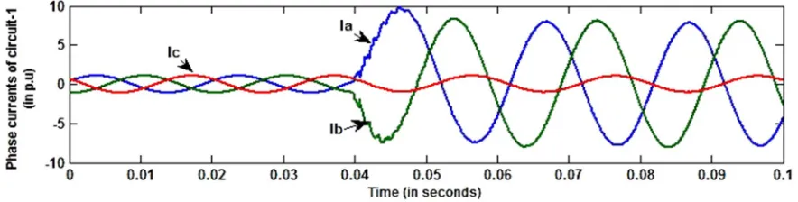
The waveforms of three phase current signals under the occurrence of “A1B1G” fault which is 10 km away from the sending end
bus with fault resistance of Rf = 1Ω and fault inception angle of Φi = 0º are shown in Fig. 2 and 3. It is very clear from Fig. 2 that
after occurrence of “A1B1G” fault there is significant change in magnitude of current signals of A phase and B phase of faulty circuit
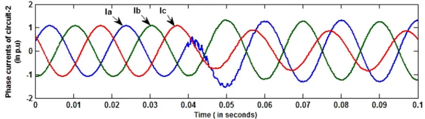
As expected, there is a change in magnitude of A and B phases of healthy circuit 2 due to the mutual coupling effect between these two circuit as shown in Fig. 3.
Figure 2: Waveforms of current signals of faulty circuit 1 on A1B1G fault at 10 km with Rf = 1Ω and Φi = 0º
Components Parameters
Three phase source
Voltage (kV) 220 Frequency(Hz) 50 Short circuit capacity (GVA) 1.25
X/R ratio 10
Transmission line
Line length (km) 100 Line voltage (kV) 220 Sequence impedance
(Ω/km)
Positive 0.0181 + j0.292 Zero 0.2188 + j1.031 Zero sequence mutual 0.20052 + j0.6535 Sequence
capacitance (nF/km)
[image:3.612.82.524.586.698.2]Figure 3: Waveforms of current signals of healthy circuit 2 on A1B1G fault at 10 km with Rf = 1Ω and Φi = 0º
III. ANN STRUCTURES FOR FAULT DETECTOR AND FAULT CLASSIFICATION
A. Inputs and Outputs
To detect the occurrence of fault in the line an ANN based fault detector is designed. The magnitudes of each fundamental current signals recorded at the relay location are evaluated by using discrete Fourier transform and the magnitudes of these current signals are used to calculate the characteristic features which will be the input for ANN. The characteristic features are calculated in terms of∆1, ∆2, ∆3 for circuit 1 and ∆11, ∆22, ∆33 for circuit 2, which are calculated as described below. First of all, from the post-fault current samples the ratios r1, r2 and r3 for circuit 1 and r11, r22, and r33 for circuit 2 are calculated as follows:
r1 = max {abs (Ia1)} / max {abs (Ib1)} r11 = max {abs (Ia2)} / max {abs (Ib2)} r2 = max {abs (Ib1)} / max {abs (Ic1)} r22 = max {abs (Ib2)} / max {abs (Ic2)} r3 = max {abs (Ic1)} / max {abs (Ia1)} r33 = max {abs (Ic2)} / max {abs (Ia2)
where Ia1, Ib1, Ic1 are the post-fault samples of the three phase currents of circuit 1 and Ia2, Ib2, Ic2 are the post-fault samples of the three phase currents of circuit 2.Next, the normalized values of r1, r2, r3, r11, r22 and r33 are found out as follows:
r1n = r1 / max (r1, r2, r3) r11n = r11 / max (r11, r22, r33)
r2n = r2 / max (r1, r2, r3) r22n = r22 / max (r11, r22, r33)
r3n = r3 / max (r1, r2, r3) r33n = r33 / max (r11, r22, r33) Finally, the differences of these normalized values are found out as follows.
Δ1 = r1n −r2n Δ2 = r2n −r3n Δ3 = r3n −r1n
Δ11 = r11n – r22n Δ22 = r22n −r33n Δ33 = r33n −r11n
These six features Δ1, Δ2, Δ3, Δ11, Δ22, Δ33 are used as the input information to train the proposed neural network. The fault detector function is to detect whether fault is present in the line or not, hence neural network for fault detector gives only one output either ‘0’ or ‘1’ where ‘0’ represents no fault case and ‘1’ represents fault case. Hence the input vector for neural network of fault detector is given by XF-det and the output of neural network of proposed fault detector is given by YF-det.
X F-det = [Δ1, Δ2, Δ3, Δ11,Δ22, Δ33] YF-det = [Fault/No fault]
similarly, the fault classifier function is to identify the faulty phase(s), hence seven outputs (six for different phases of parallel circuits and one for detection of presence of ground ) are taken as neural network outputs for fault classifier. Hence the ANN input vector X F-classand ANN output vector YF-classfor the fault classification are given as:
X F-class = [Δ1, Δ2, Δ3, Δ11,Δ22, Δ33] YF-class = [A1, B1, C1, A2, B2, C2, G]
B. Design process
The number of inputs and outputs in the ANN of fault detector and classifier was decided then the number of layers and the number of neurons in each layer was to be considered. After analyzing different neural networks with combinations of activation functions, it was decided to use a four layers neural network with 6 neurons in the input layer, 12 neurons in the first hidden layer and 8 neurons in the second hidden layer and 1 neuron in the output layer (6-12-8-1) for fault detection as shown in Fig. 4. After analyzing different transfer functions ‘logsig’ transfer function was used for both hidden layer and for output layer ‘purelin’ transfer function was used in neural network of fault detection task.
5.‘Logsig’ transfer function was used for both hidden layers and for output layer ‘purelin’ transfer function was used in neural network of fault classifcation task.
[image:5.612.132.454.241.326.2]Figure 4: Architecture of ANN Based Fault Detector
Figure 5: Architecture of ANN Based Fault Classification
C. Training process
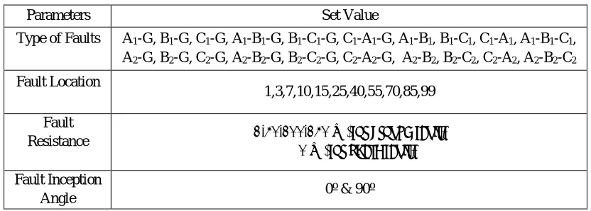
The Training data set is necessary for appropriate training of ANN hence the training data set for fault detection and classification task were generated for all possible faults types such as phase-ground, phase-phase, phase-phase-ground and three-phase under varying system conditions that is at different fault locations, fault inception angles and fault resistance. The types of fault, fault locations, fault resistances and fault inception angle used for preparing training data set are shown in table 2.
Table 2: Training Data Pattern Generation
Hence the total numbers of fault cases simulated for phase(s) to ground fault are 12 x 11 x 4 x 2= 1056 and the total numbers of fault cases simulated for phase(s) to phase fault are 8 x 11 x 1 x 2= 176. Therefore the total number of training patterns generated for fault detection task is 1232(fault cases) + 1(no fault case) = 1233 and 1232 for fault classification task. Levenberg– Marquardt (LM) training algorithm was used for training of neural networks of both fault detector and fault classifier. This learning method converges very quickly and hence the mean squared error (mse) decreases to 4.36e-09 in 31 epochs for fault detector as shown in figure 6 and for fault classifier the mse decreases to 9.34e-05 in 168 epochs as shown in figure 7.
Parameters Set Value
Type of Faults A1-G, B1-G, C1-G, A1-B1-G, B1-C1-G, C1-A1-G, A1-B1, B1-C1, C1-A1, A1-B1-C1,
A2-G, B2-G, C2-G, A2-B2-G, B2-C2-G, C2-A2-G, A2-B2, B2-C2, C2-A2, A2-B2-C2
Fault Location
1,3,7,10,15,25,40,55,70,85,99 Fault
Resistance 1,50,100,150 Ω (for ground fault)
& 0 Ω (for phase fault)
Fault Inception
Angle 0º & 90º
[image:5.612.98.514.452.601.2]Figure 6: MSE performance for fault detector Figure 7: MSE performance for fault classifier IV. RESULTS OF ANN BASED FAULT DETECTOR AND FAULT CLASSIFIER
After finishing the training process, the accuracy of the trained neural network was extensively tested using independent test data sets which consisting of different fault scenarios that had not been used previously in training process. Test data sets were generated for different fault types by varying fault resistance Rf, fault inception angles Φi and fault location Lf for investigating the effect these
parameters on the performance of the proposed protection technique. The neural network was extensively tested and validated by providing different fault scenarios by varying fault resistance Rf (0-145 Ω), fault locations Lf (0-99 km) and fault inception angles Φi (0-360°).
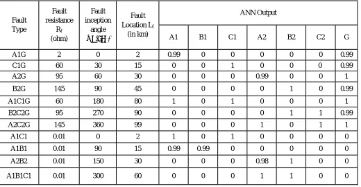
Table 3: ANN based Fault Detector & Classifier test results
From the test results given in Table 3, it is clear that the developed ANN based Fault Detector and Classifier is able to detect and classify the fault rapidly and accurately. Thus, even the extreme fault cases of high fault resistance near the far end of the line was detected and classified rapidly by the developed ANN based Fault Detector and Classifier.
Fault Type
Fault resistance
Rf
(ohm)
Fault inception
angle
Φi (deg)
Fault Location Lf
(in km)
ANN Output
A1 B1 C1 A2 B2 C2 G
A1G 2 0 2 0.99 0 0 0 0 0 0.99 C1G 60 30 15 0 0 1 0 0 0 0.99 A2G 95 60 30 0 0 0 0.99 0 0 1 B2G 145 90 45 0 0 0 0 1 0 0.99 A1C1G 60 180 80 1 0 1 0 0 0 1 B2C2G 95 270 90 0 0 0 0 1 1 0.99 A2C2G 145 360 99 0 0 0 1 0 1 1
[image:6.612.37.557.383.653.2]V. CONCLUSIONS
An accurate fault detection and classification technique using ANN has been proposed, which can be implemented for the digital protection of the double circuit power transmission line. The protection algorithm employs the three phase current signals of both the circuit-1 and circuit-2 as input for the corresponding neural network for fault detector and fault classifier. The proposed protection algorithm effectively eliminated variations in fault resistance, fault location and fault inception angle. The performance of the proposed scheme was tested for large numbers of offline test cases in which all possible types of faults with variations in fault resistance Rf (0-145 Ω), fault location Lf (0-99 km) and fault inception angle Φi (0-360°) were considered . The simulation test
results concludes that the proposed ANN based Fault Detector and Fault Classifier can be implemented to support a new generation of protective relay systems at faster speed with high accuracy.
VI. ACKNOWLEDGMENT
I would like to sincerely thank Mr. Lumesh Kumar Sahu, Assistant Professor (Dept. of Electrical Engg.) who provided expertise that greatly assisted the research work.
REFERENCES
[1] A. Ferrero, S. Sangiovanni, and E. Zapitelli, “A fuzzy set approach to fault type identification in digital relaying,” IEEE Trans. on Power Delivery, vol. 10, pp. 169–175, Jan. 1995.
[2] Anamika Jain, A.S.Thoke and Ebha Koley, “Fault Classification and Fault Distance Location of Double Circuit Transmission Lines for Phase to Phase Faults using only One Terminal Data”, Third International Conference on Power Systems, Kharagpur, 2009.
[3] Sanaye-Pasand, M.; Khorashadi-Zadeh; "An extended ANN-based high speed accurate distance protection algorithm," Electrical Power and Energy Systems, pp. 387–395, 2006.
[4] J.Gracia, A. J. Mazon, and I. Zamora, “Best ANN structures for fault location in single and double-circuit transmission line”, IEEE Trans. On Power Delivery, vol. 20, no. 4, pp. 2389-2395, Oct.2005
[5] R.N. Mahanty, P.B. Dutta Gupta, “Application of RBF neural network to fault classification and location in transmission lines”, IEE Proc. Gen. Trans. Dist. 151 (2) (2004) 201–212.
[6] Carlo Cecati, Kaveh Razi,” Fuzzy-Logic-Based High Accurate Fault Classification of Single and Double-Circuit Power Transmission Lines”, International Symposium on Power Electronics, Electrical Drives, Automation and Motion, 2012.
[7] Moez Ben Hessine, Houda Jouini and Souad Chebbi, “A New and Accurate Fault Classification Algorithm for Transmission Lines using Fuzzy Logic System ”, Wulfenia journal . Vol 20, No. 3;Mar 2013.
[8] Javad Sadeh, Hamid Afradi,” A new and accurate fault location algorithm for combined transmission lines using Adaptive Network-Based Fuzzy Inference System”,Electrical Power System Research, 79 (2009) 1538–1545.
[9] P. K. Dash, A. K. Pradhan, and G. Panda, “A Novel Fuzzy Neural Network Based Distance Relaying Scheme,” IEEE Trans. on Power Delivery, vol. 15, no. 3, July 2000.
[10] Biswarup Das, and J. Vittal Reddy, “Fuzzy-logic-based fault classification scheme for digital distance protection,” IEEE Trans. On Power Delivery, vol. 20, no. 2, pp. 609-616, April 2005.
[11] Omar A.S. Youssef,” A novel fuzzy-logic-based phase selection technique for power system relaying”, Electrical Power System Research, 68 (2004) 175–184. [12] Biswarup Das, and J. Vittal Reddy, “Fuzzy-logic-based fault classification scheme for digital distance protection,” IEEE Trans. On Power Delivery, vol. 20, no.
2, pp. 609-616, April 2005.
[13] A.H. Osman,T. Abdelazim, O.P. Malik, Transmission line distance relaying using on line trained neural networks, IEEE Trans. Power Deliv. 20 (2) (2005) 1257–1264.