Evaluation of Different Multilevel Inverter
Topologies for Harmonics and Power Losses
Arun Kumar M1, Sanjay Lakshminarayanan2
1
Department of EEE, New Horizon College of Engineering, Bangalore.
2
Department of EEE, BMS Institute of Technology and Management, Bangalore.
Abstract: With the emission norms becoming more stringent and escalating cost of hydrocarbon fuels automotive companies are developing Electric Vehicles (EV), Hybrid Electric Vehicles (HEVs), and Plug-in Hybrid Electric Vehicles (PHEV). All this vehicles need a traction motor and a power converter to drive the traction motor. The requirements for the power converters include high peak power, optimum consumption of energy, low output harmonics and inexpensive circuit. One of the promising technologies that can be made to meet these requirements is Multilevel Inverters (MLI). This paper discusses the three types MLI namely of diode clamped, cascaded H-bridge, and reduced switch multilevel inverters (MLI). This paper focuses on evaluation of harmonics and power losses in the above inverter topologies. Based on the simulation results obtained it is found that Total Harmonic Distortion (THD) of MLI is less compared to H-Bridge inverter where as power loss in H-Bridge inverter is less compared to MLI.
Keywords: Multilevel inverter, Total Harmonic Distortion, Traction Motors.
I. INTRODUCTION
Power electronic converters which use semiconductor devices are becoming more and more popular for various industrial applications, especially dc/ac PWM inverters. This type of inverters have been extending their range of use in industry because they provide reduced energy consumption, better system efficiency, improved quality of product, good maintenance, and so on. At the same time the semiconductor devices used as switches have certain limitation especially at high power applications.
To overcome these limitations series and parallel connection of switches is often considered an effective solution. In addition, stepped waveform in the output of inverter has better harmonic spectrum than 2-level inverter and can be operated at switching frequencies. As a result, a multilevel power converter structure has been introduced as an alternative in high power and medium voltage situations [1–3].
The principal function of MLI is to synthesize a desired ac voltage from several separate dc sources, which may be obtained from batteries, fuel cells, or solar cells [1].
The desired output voltage waveform can be synthesized from the multiple voltage levels. With an increasing number of dc sources, the inverter output voltage waveform approaches a nearly sinusoidal waveform. The small output voltage step results in high quality output voltage, reduction of voltage stresses on power switching devices, lower switching losses and higher efficiency.
A. The use of MLI to drive the main traction drives in electrical vehicles has the following advantages [2-4]: 1) They are suitable for large VA-rated motor drives, and traditional 230 V or 460 V motors can be used.
2) Higher efficiency is expected for these multilevel converter systems because higher voltages can be utilized and the switching frequency of the devices is at a minimum.
3) Low voltage switching devices can be used.
4) No electromagnetic interference (EMI) problem or common-mode voltage/current problem exists. 5) No charge unbalance problem results from either charge mode or drive mode.
The major drawback associated with MLI is the use of great number of power switches. With increase number of power switches there is considerable voltage drop across the power switches putting a limitation on the available output voltage and efficiency of the inverter. Thus it becomes imperative to study the performance these MLIs with respect to power loss in the converter circuits and advantages it provides in case of THD with increase use of power switches.
II. MULTILEVELINVERTERTOPOLOGIES
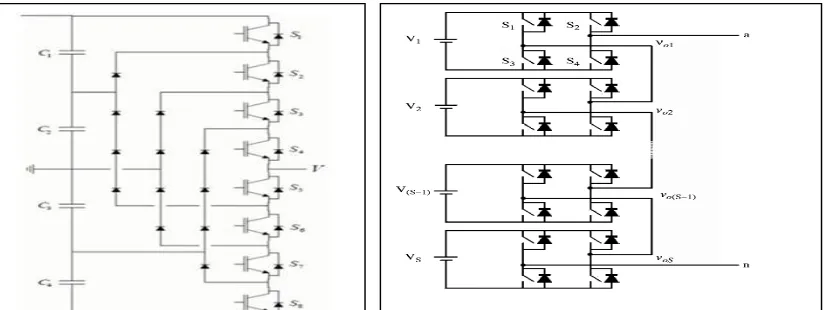
A. Diode Clamped Multilevel Inverter
A five-level diode-clamped inverter is shown in Fig 1. Each of the three phases of the inverter shares a common dc bus, which has been subdivided by four capacitors into five levels. The voltage across each capacitor is Vdc, and the voltage stress across each
switching device is limited to Vdc through the clamping diodes. Table 1 lists the output voltage levels possible for one phase of the
inverter with the negative dc rail voltage V0 as a reference. State condition 1 means the switch is on, and 0 means the switch is off.
Each phase has five complementary switch pairs such that turning on one of the switches of the pair require that the other complementary switch be turned off. The complementary switch pairs for phase leg A are (S4, S8), (S3, S7), (S2, S6) and (S1, S5). For a
Five-level inverter, a set of five switches is on at any given time.
TABLE 1.DIODE CLAMPED VOLTAGE LEVELS AND THEIR SWITCH STATES
Output Va0
Switch States
S1 S2 S3 S4 S5 S6 S7 S8
V5=Vdc 1 1 1 1 0 0 0 0
V4=3Vd
c/4
0 1 1 1 1 0 0 0
V3=Vdc/
2 0 0 1 1 1 1 0 0 V2=Vdc/
4 0 0 0 1 1 1 1 0 V1=0 0 0 0 0 1 1 1 1
The configuration in Fig 1 can be modified by replacing each capacitor with batteries that can be used for EVs.
B. The main advantages and disadvantages of multilevel diode-clamped converters are as follows [1-3]. 1) Advantages
a)All of the phases share a common dc bus, which minimizes the capacitance requirements of the converter. b)The capacitors can be pre-charged as a group.
c)The control method is simple.
d)Inverter efficiency is high because all devices are switched at the fundamental frequency.
2) Disadvantages
a) Excessive clamping diodes are required when the number of levels is high.
b)It is difficult to control the real power flow of the individual converter in multi-converter systems. c)Cascaded Multilevel Inverter
[image:3.612.81.493.549.704.2]A single-phase structure of an m-level cascaded MLI is shown in Fig 2. It consists of separate dc source connected to a H-bridge inverter. Each inverter level can generate three different voltage outputs, +Vdc, 0, and -Vdc by connecting the dc source to the ac output by different combinations of the four switches, S1, S2, S3, and S4. To obtain +Vdc, switches S1 and S4 are turned on, whereas -Vdc can be obtained by turning on switches S2 and S3. By turning on S1 and S2 or S3 and S4, the output voltage is 0. The ac outputs of each of the different H-bridge inverter levels are connected in series such that the synthesized voltage waveform is the sum of the inverter outputs. The number of output phase voltage levels m in a cascade inverter is defined by m = 2s+1, where s is the number of separate dc sources. The phase voltage Van = Vo1 + Vo2 + Vo3 +Vo4 +Vo5.
C. The main advantages and disadvantages of multilevel cascaded H-bridge converters are as follows [8, 9]. 1) Advantages
a) The number of possible output voltage levels is more than twice the number of dc sources (m = 2s + 1). b)The series of H-bridges makes for optimized circuit layout and packaging, resulting in reduced cost. c)Soft-switching techniques can be used to reduce switching losses and device stresses.
2) Disadvantages
a) Excessive clamping diodes are required when the number of levels is high.
It is difficult to control the real power flow of the individual converter in multi-converter systems.
D. Reduced Switch Multilevel inverter
A simple 5-level MLI configuration with reduced number of switches is shown in Fig 3. It consists of four switches S1 to S4 which generates stepped waveform based on given gate drive. When all the four switches i.e., S1 to S4 are off the output voltage is zero. Table 1 gives the switch state and output voltage level for each state. Switches S5,S6 and S7, S8 are made to conduct for π interval alternatively with overall time period of 2π.
Fig 3. Reduced Switch Multilevel Inverter
V4
V3
V2
V1
S8
S7
S6 S5
S4
S3
S2
S1
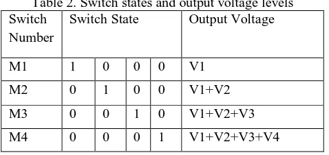
Table 2. Switch states and output voltage levels Switch
Number
Switch State Output Voltage
M1 1 0 0 0 V1
M2 0 1 0 0 V1+V2
M3 0 0 1 0 V1+V2+V3
M4 0 0 0 1 V1+V2+V3+V4
Switch state – 1 indicates the switch is on and switch state – 0 indicates the switch is off.
E. The main advantages and disadvantages of Reduced Switch Multilevel converters are as follows. 1) Advantages
a) As the number of voltage levels increases the number of conducting devices remains the same. b)All of the phases share a common dc bus.
c)The control method is simple.
d)Inverter efficiency is high because all devices are switched at the fundamental frequency. 2) Disadvantages
a) As the number of voltage levels increases the voltage stress on the device also increases. b)It needs separate DC source for each level hence limiting its application.
III.SWITCHINGMETHODOLOGY
The switching angles for switches are calculated in such ways that lower dominant harmonics are eliminated. For this purpose Fourier analysis need to be done to determine the frequency spectra of the output waveform.
The Fourier series of n-step output waveform is given by
( ) = ∑ ∑ cos (ℎ ) (ℎ )
ℎ ℎ
∞ (1)
where, Vdc:Voltage of voltage sources for each cell that is unity, θi:the switching angle, h:the harmonic order, K:Number of voltage levels. For eliminating 3rd, 5th, and 7th harmonics following equation are used which is obtained from equation (1). ℎ =3 (cos( ) + (cos( ) + (cos( ) (2)
ℎ =3 (cos(3 ) + (cos(3 ) + (cos(3 ) (3)
ℎ =3 (cos(5 ) + (cos(5 ) + (cos(5 ) (4)
ℎ =3 (cos(7 ) + (cos(7 ) + (cos(7 ) (5)
Equations (2) to (5) are for the harmonics that should be eliminated, so (3) to (5) should be equated to zero for eliminating the 3rd, 5th and 7th harmonics. The resulting equations are: 4= 3 (cos( ) + (cos( ) + (cos( ) (6)
0 =3 (cos(3 ) + (cos(3 ) + (cos(3 ) (7)
0 =3 (cos(5 ) + (cos(5 ) + (cos(5 ) (8)
0 =3 (cos(7 ) + (cos(7 ) + (cos(7 ) (9)
IV.MOSFETLOSSCOMPUTATIONMODEL
The metal-oxide semiconductor field-effect transistor (MOSFET) is a semiconductor device consisting of three terminals namely drain, source and gate. Gate is the control terminal. MOSFET conducts when (g < 0) and does not conduct when (g = 0). The MOSFET is connected in parallel with an internal diode that turns on when the MOSFET is reverse biased (Vds < 0) and no gate signal is applied (g=0). The model is simulated by an ideal switch controlled by a logical signal (g > 0 or g = 0), with a diode connected in parallel. Figure 3 gives MOSFET model, Ron is internal resistance of MOSFET when it is conducting. Rd is the internal
diode resistance of MOSFET when it not conducting and Vf is the forward voltage drop of internal diode. The drain to source voltage,
Vds of MOSFET is defined as
A. = ∗ when MOSFET is on B. = ∗ − when is MOSFET is off
For computing losses in MOSFET current through it and voltage across it is measured and multiplied and mean for one time period is taken, which gives the total loss taking place in the MOSFET.
V. MLIPOWERLOSSANALYSIS
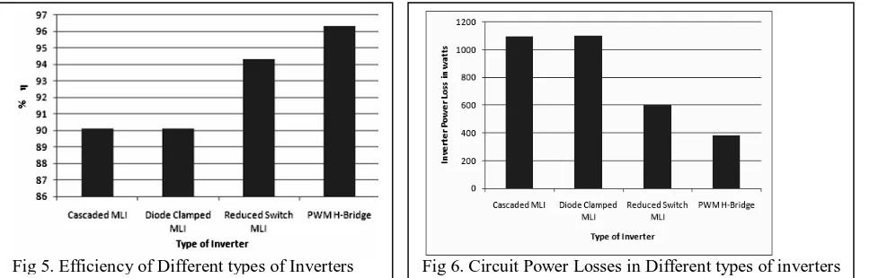
In this section Power loss analysis on three different types of MLIs namely Diode clamped, Cascaded, Reduced switch and PWM H-Bridge inverter is discussed. The inverters should give RMS output voltage of 230V single phase, frequency of operation is 50Hz, and number of levels in case of MLIs is seven for a purely resistive load of 10KWs. Figure 5 gives the plot of efficiency of different types of inverter. It is observed from plot that PWM-Bridge inverter has the efficiency of 96%, Reduced switch MLI is 94% and cascaded and Diode clamped MLI has efficiency of around 90%. Figure 6 gives the plot of power losses in the different types of inverter circuits.
[image:6.612.137.389.207.331.2]From the plot it is observed that Cascaded and Diode clamped MLI have circuit power loss of 1100 watts where as PWM H-Bridge inverter has circuit power loss of around 380 watts and that of reduced switch MLI has circuit power loss of 600 watts. The increased power loss in Cascaded and Diode clamped MLI can be attributed to the fact that the conducting devices are more. In case of the PWM Bridge inverter the number of conducting devices is less and Reduced switch MLI it is one device more than the PWM H-Bridge inverter. This is one of the reason for reduced efficiency in case of Cascaded and Diode clamped MLI as can be observed in figure 5.
[image:6.612.42.526.473.628.2]Fig 4. MOSFET model
VI. MLIHARMONICANALYSIS
The output waveform for 7-level inverters is shown in figure 7. The output waveforms obtained for diode clamped, cascaded and reduced switch MLIs are same and is shown in figure 7 and figure 8 gives the output waveforms for PWM H-Bridge inverter.
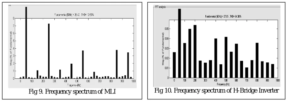
[image:7.612.44.517.117.255.2]The FFT analysis of the waveform is shown in Figure 9. It is seen that 3rd, 5th, and 7th components are considerably reduced with the use MLI and THD is found to be 12.55% as shown in figure 9. THD in case of PWM H-Bridge Inverter is 64.36% has can be seen in figure 10.
VII. CONCLUSIONS
In this paper power loss and harmonic analysis of three different types of MLI is carried out and compared with the 2-level inverter. It is observed that the efficiency of two level inverter with sinusoidal pulse width modulation is highest but THD is very poor. Reduction of the power loss and improved harmonic spectrum in comparison other topology is the main advantage of the reduced switch MLI. The proposed topology can be a good solution for applications that require high power quality, or applications that have considerable numbers of dc voltage sources like electric vehicles.
REFERENCES
[1] J. Rodriguez, J. S. Lai and F. Z. Peng, “Multilevel inverters: Survey of topologies, controls, and applications,” IEEE Trans. Ind. Applicat., vol. 49, no. 4, pp. 724-738, Aug. 2002.
[2] J. S. Lai and F. Z. Peng, “Multilevel converters–A new breed of power converters,” IEEE Trans. Ind. Applicat., vol. 32, pp. 509–517, May/June 1996.
[3] L. M. Tolbert, F.-Z. Peng, and T. Habetler, “Multilevel converters for large electric drives,” IEEE Trans. Ind. Applicat., vol. 35, pp. 36–44, Jan./Feb. 1999.
[4] L. M. Tolbert and F.Z. Peng, “Multilevel Converters as a Utility Interface for Renewable Energy System”, IEEE Proceedings-Power Eng. Soc. Summer Meeting, Seattle, WA, 2000, pp. 1271-1274.
[5] L. M. Tolbert, F. Z. Peng, T. Cunnyngham and J. N. Chi-asson, “Charge Balance Control Schemes for Cascade Multilevel Converter in Hybrid Electric Vehicles,” IEEE Transactions on Industrial Electronics, Vol. 49, No. 5, 2002, pp. 1058-1064.
[6] A. Emadi, S. S. Williamson and A. Khaligh, “Power Electronics Intensive Solution for Advanced Electric, Hybrid Electric, and Fuel Cell Vehicular Power Sys-tems,” IEEE Transactions on Power Electronics, Vol. 21, No. 3, 2006, pp. 567-577.
[1] J. Dixon, J. Pereda, C. Castillo and S. Bosch, “Asymmetrical Multilevel Inverter for Traction Drives Using Only One DC Supply,” IEEE Transactions on Vehicular Technology, Vol. 59, No. 8, 2010, pp. 3736-3743.
Fig 7. Multilevel inverter output waveform.
Fig 9. Frequency spectrum of MLI
Fig 8. PWM H-Bridge Inverter Output Waveform
[image:7.612.54.511.305.466.2]