Intelligent Traction System
G Jeevitha
[1], N Magadevi
[2], T Bharathi
[3], V Gowtham
[4], M Sivaramaganesh
[5]P.G Scholar, Embedded System Technologies, S.A Engineering College, Chennai[1][3][4][5].
Ph.D. Scholar, Anna University, Chennai[2].
Abstract — A new kind of approaches are exhibited to ensure the railway safety and thereby assuring a secured travel. This project mainly performs the detection of faults that occurs due to cracks on tracks, obstacle and explosives. For better and safe travel, the cracks on rails are periodically checked, for this, left and right alignment are said to be performed using IR sensors and added Ultra Sonic crack detection can also be performed for effective and better results. Metal(proximity)sensor and obstacle sensor check is carried out in order to avoid the running train either get collided or hit by an obstacle. Communication between the driver and control room can be done using radio-based operation. Promisingly, a safe and secured travel can be assured for the passengers using this transportation system.
Keywords –Wireless technology, Ultra-Sonic crack detection, sensors, buzzer system.
I. INTRODUCTION
Railway transportation system is one among the commonly used economical transportation system in India. Almost nearly 24 million passengers use the railway system on a daily basis. Railway authorities had made an analysis of the recent accidents and customer complaints to provide a safe and secured system which can be widely used throughout the railway connecting system. The major reason which is being analysed for the cause of the railway accidents is the Signalling System which is being done manually either by a telephonic intercom call or by a walkie talky, were the signal information is being sent from a station to the next upcoming station, and with this receiving information signal for the trains are said to be operated throughout the network. In Jammu & Kashmir, due to extreme cold weather conditions, the Loco-Pilots find it difficult to have an accurate view of the Signal. Hence, a complete networking system can be implemented, were an automatic signalling can be done. The trains can be
controlled which would provide a better traffic control system as well as the monitoring can be done.
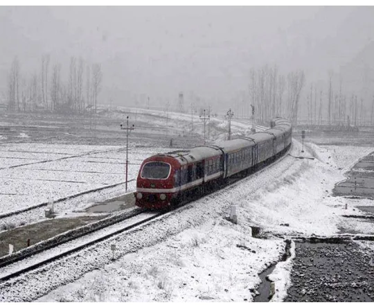
With the increased usage of railway system, the transportation system continue to upgrade at a remarkable note to maintain the efficiency, reliability, safety and security. The lack of safety and security is caused mainly due to fact that a periodic/random fault identification is not properly done. Recent advances concentrates in vehicle health monitoring system, [7] E-BMA(Bit Map Assisted) protocol concentrates on developing better energy efficiency and to monitor the dynamic behaviour of railway wagons. Indian railways have planned for a trail check for the avoidance of the above discussed factors in the DEMU(figure 1) train which is a recent technology train being introduced in the Sub-Urban & Rural places across India were the people density is less. DEMU(Diesel Electric Multiple Units) is a self-propelled train consisting of Driving Power Car and Trailer Cars which would run at a speed of 110 km/h.
super-are measured using a surveying system [10]LVDT(Linear Variable Differential Transformers). And the importance of train detection in railway signalling, control systems and its highlights are discussed [3]. A new approach to railway traffic analysis is to reconstruct the speed profile and its energy consumption [6]. The analytical model and simulation of the traction system are developed and its results are simulated using Proteus, MPLABs.
Fig 1. A view of a DEMU Train in J&K
II. BASIC COMPONENTS AND PRINCIPLES OF THE SYSTEM
Basic principle of the system is to communicate the information about weather, obstacle or any other emergency details between the train and control room. The medium of communication is done using RFID. The general block diagram is shown in figure 2.
Fig 2 General block diagram of the project
A. Block Signaling
In this section, automatic signaling concept is defined.
Signals are placed to indicate the approaching train’s action and
depending on the signaling system, the operational speed of the train will be changed. Figure 3 shows the two-aspect signaling systems, train can move only when there is a green signal and halts when it is red and added the braking distance from line speed is distributed across the block sections. Blocks are said to be the railway lines that are divided into sections. By using the
PIC16F877A controller the signals are automated and
[image:3.612.365.531.448.568.2]transmitted through RF transmitter.
Fig 3. Block diagram for train signal
Basic design includes five parts: master module, fault sensing circuit, RF(receiver and transmitter), motor and LCD. The block diagram of the project is shown in figure 4. PIC16F877A is selected as microcontroller for the master module. PIC(Peripheral Interface Controller) as 8Kx14 Flash program memory, high performance RISC based CPU, low power consumption and it has up to 14 sources of interrupts. Fault sensing circuit used to find the defects and sends information to the respective systems through RF(Radio-Frequency). Motor drive is used to control the speed of the motor.
Fig 4.Block diagram of the project
C. Station Side
[image:4.612.52.277.325.468.2]Station side block consists of RF Receiver(Rx) module, decoder, PIC microcontroller, LCD and buzzer. The station side diagram is shown in figure 5.
Fig 5. Block diagram of Station side signal
PIC uses programmable serial port(USART), RF-Rx is used to receive the information transmitted by the train, it is then decoded and sent to the controller. The information is stored in RAM of PIC16F877A and displayed through LCD and buzzered at the right time.
D. System’s Operating Principle
On-board equipment subsystem (figure 4) consists of control unit PIC16A877, fault sensing unit, LCD module, encoder and decoder, motor drive. The transmitted information is received
through the RF to the driver’s cabin, signal information which will direct the driver to operate the train, train’s speed and
fault information, it is decoded to the controller. As a immediate move alerted by buzzer and display(LCD) at the right time.
III. SIMULATION RESULTS
General simulation for Intelligent train model(figure 6) illustrating the entire techniques like automatic traffic signal control, detecting train track fault and bomb detection. Various sensors like IR sensors, Obstacle sensors, Metal(Proximity) sensors are used to detect the fault. PIC microcontroller plays a vital role in executing the simulation.
Fig 6. General simulation of intelligent train model(indicating the signal is in red, train is in halt).
MPLABX IDE is a software program that runs on a PC (Windows, Mac OS, Linux) to develop applications for Microchip microcontrollers and digital signal controllers. It is called an Integrated Development Environment (IDE), because it
provides a single integrated “environment” to develop code for
embedded microcontrollers. Proteus is software for
[image:5.612.355.542.134.260.2]microprocessor simulation, schematic capture, and printed circuit board (PCB) design. It is developed by Lab center Electronics. MPLABX does the work of compiling, debugging, Embedded C is used for programming. Simulations are run using a software, Proteus.
Fig 7. Simulation result for Obstacle sensor
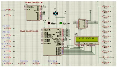
The IR Obstacle sensor is used to detect the faults, mainly designed for robust operation. Figure 7, shows the fault that is detected using the obstacle sensor. Fire sensors senses the fire as a signal and pass the information to the nearest railway station and added a buzzer is placed to alert the passengers, also alert the driver to make the train come to halt. In figure 8, shows the result of fire sensing module.
Fig 8. Simulation result of Fire sensor
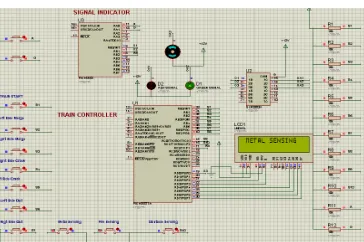
[image:5.612.39.287.329.457.2] [image:5.612.354.544.419.528.2]Fig 9. Simulation result of Metal detection
In the above figure 9, fault is detected using metal sensing. Proximity sensor is used for the high reliability and long functional life. It is able to detect the presence of nearby objects without any physical contact and some sensors have variation of the nominal range or means to report a graduated detection distance. LCD(16x2) used to display the information
to driver’s cabin and to the control room.
IV. CONCLUSION
In a demanding society, by using advanced techniques, railway network can be brought under a single cloud radar system which efficiently make passengers journey comfort. In this paper, considering the traffic conditions various parameters are introduced for the betterment of safety and added it shows improved adaptability to weather conditions, maintainability of centralized(cracks) and simplified equipment design. Sensors like IR, Proximity and fire sensors are used to detect the faults(obstacle, metal, fire). In real time, Ultra Sonic crack detection can be used to detect the cracks on tracks, this technique provides accurate and highly efficient results. GPRS can be used instead of RFID, it provides with no distance restrictions and high reliability. The authors hope that their idea can be implemented in large scale in the long run to facilitate better safety and secured travel.
ACKNOWLEDGMENT
The authors wish to thank the ICF(Integral Coach Factory) for providing the guidance to do this project.
REFERENCES
[1] Goh.S., ‘Energy saving by using regenerating braking as normal train operation’, IET conference on Railway Traction Systems, April 2010, pp. 1-7.
[2] H S Bhatia, ‘Telecommunication Supporting Signalling and
Railway Operations’ , Conference on Railway signalling and control systems, May 2012, pp.144 –161.
[3] J. W. Palmer, ‘The Need for Train detection’, 11th IET Professional Development Course on Railway Signalling and Control, pp.60 –74, May 2012.
[4] A.C. Elliott, ‘Human factors for Railway Signalling and Control System’, IET Professional Development Course on Railway Signalling and Control, Derby, UK , pp.236 – 248, May 2012.
[5] RuNiu& Tao Tang, ‘Automatic Safety Analysis of
computer-based railway signalling system’, IEEE international conference on serviceoperations, logistics, and informatics, Jul 2011 , pp.484 –490.
[6] Albrecht.T, Gassel. C., Knijff. J., van Luipen, J, ‘Analysis of energy consumption and traffic flow by means of track occupation data’, Dresden University of Technology, IET conference on railway traction systems, April 2010, pp. 1-7.
[7] Boscardin,Cai, S., Gao, R.X.Gong, W., ‘Energy efficient MAC protocol for condition monitoring sensor networks’, 43rd
IEEE Conference on Decision and Control, Dec 2004, vol.2, pp.1496 –1501.
[8] Haifeng Wang, Felix Schmid, Lei Chen, Clive Roberts and
Tianhua Xu, ‘A Topology-Based Model for Railway Train
Control Systems’, IEEE transactions on intelligent transportation systems, vol. 14, no. 2, pp. 819-827, June 2013.
[9] Selvamraju Somalraju, vigneshwar Murali, Gourav Saha, Dr.
V. Vaidehi, ‘Robust Railway Crack Detection Scheme(RRCDS)
Using LED-LDR Assembly’, ICRTIT, 2012, pp. 477-482.
[10] Burak Akpinar and Engin Gulal, ‘Multisensor Railway
January 2012.
[11] Massimo Leonardo Filograno, Pedro Corredera Guillen, Alberto Rodriguez-Barrios, Sonia Martin-Lopez, ‘Real-Time Monitoring of Railway Traffic Using Fiber Bragg Grating
Sensors’, IEEE sensors journal, vol. 12, no. 1, pp. 85-92, January 2012.
[12] Maria Dominguez, Antonio Fernandez-Cardador, Asuncion P. Cucala, and Ramon R. Pecharroman, ‘Energy Savings in Metropolitan Railway Substations Through Regenerative Energy
Recovery and Optimal Design of ATO Speed Profiles’, IEEE
transactions on automation science and engineering, 2012, pp.1-8.
[13] Railway signaling, [Online], Available: