6
I
January 2018
A New Zonal Based Vehicle Speed Control System
Gopi Krishna Saramekala1, Ch. Umashankar2 Department of Electronics and Communication Engineering,
1
St. Martin’s engineering College, Secunderabad-500014, Telangana, India
2
MLR Institute of Technology, Secunderabad-500043, Telangana, India
Abstract: In this paper a new zonal based vehicle speed control system was presented. In conventional system the speed of the vehicle is controlled and it is same everywhere. However, it is not acceptable to maintain the same speed of the vehicle in sensitive and normal areas, respectively. Hence to overcome this problem I propose a new zonal based vehicle speed control system. The main objective of the proposed system is to fix the maximum speed of the vehicle in different zones. In this work the roads are divided in to 4 zones. They are schools, hospitals, hill areas and highways. The developed embedded system contains a transmitter and a receiver, where the transmitter is placed in a base station to send the signal to all the vehicles in that zone and a receiver is placed in a vehicle to receive the signal and fix the maximum speed. The developed system was tested with the help of a prototype for different cases and the accuracy is almost 99%.
I. INTRODUCTION
Due to the advances in the technology, the average speeds of the vehicles are increased in the 21st century. Recent times the human beings are driving the vehicles with high speed even in limited speed areas due to which accidents are occurring recurrently. According to Global status report on road safety 2015, the total number of road traffic deaths has reported at 1.25 million per year worldwide, with maximum road accident rates in low-income countries [1, 2]. They also reported that these accidents are happening due to drunk and drive, over speed, without wearing motorcycle helmets or child restraints. Above all, driving the vehicles with over speed is the primary reason for this huge number of accidents. Usually, in order to avoid accidents due to over speed and to alert the drivers in speed limited places, the highway department used to place signboards. But most of the time people will not follow the speed limit which was mentioned in the signboards. Hence, to control the maximum speed of the vehicle automatically we developed a system which intimates the driver before entering in to the zones and the sets the maximum speed limit automatically using RF technology and ARM controller. Additionally, the proposed system contains a Display controller meant for vehicle’s speed control and monitors the zones, which can run on an embedded system.
This paper begins by identifying three stages in the likely evolution of these advanced vehicle control systems (AVCS), showing how AVCS is related to the other IVHS functions. The technological elements of AVCS, corresponding to needed research and development work, are then described. The international state of the art in these technologies is reviewed, and the paper concludes with a discussion of an evolutionary progression that could be followed to lead from present-day driving to the long-term concept of an automated freeway network.
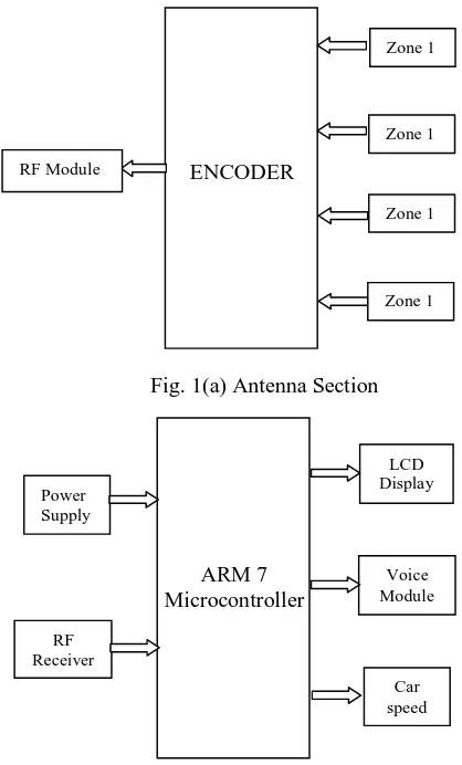
II. BLOCKDIAGRAM
Fig. 1(b) Vehicle control setup section
III. EXPERIMENTALSETUP
[image:3.612.172.381.87.433.2]The experimental setup for the zonal based control vehicle is shown in Fig. 2. The following requirements for the experimental setup are adopter, care model with equipped with the control set, remote controller to manually run vehicle and transmitter. Adopter is used to provide the necessary power supply requirements to equipped vehicle. Equipment in the vehicle will get into zonal speed when it enters into any zonal speed. Remote control is used as a hand controller to drive the vehicle. Transmitter setup will radiate RF signals with carry respective zonal speed control data.
Fig 2 Experimental setup ENCODER Zone 1 RF Module Zone 1 Zone 1 Zone 1 ARM 7 Microcontroller LCD Display RF Receiver Voice Module Car speed Power Supply
[image:3.612.172.436.546.722.2]zone, automatically zonal speed will assign to the vehicle so that it cannot cross zonal speed limit. At the same moment the LCD display continuously shows up and audio output form voice module tell us speed limit and Zone name. As soon as out of range its limit is released so free to drive on own speed.
Fig 3 Working operation model
IV. RESULTSANDDISCUSSION
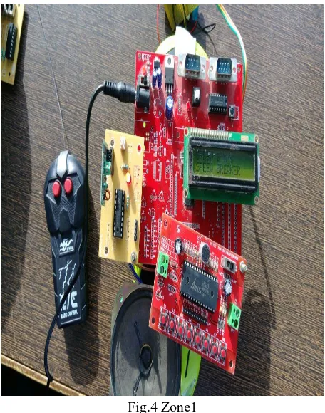
[image:4.612.187.434.130.302.2]Zone1 is considered as a residential zone/Speed breaker zone. When the vehicle comes into respective zone then the controller recognize the signals from Tower/Transmitter and it sets the zonal speed limit to the vehicle and at the same time the speed is displayed and the voice module tells us its zone speed limit and in which zone vehicle currently is in. Figure 4 shows the vehicle is in Speed break zone and its speed Limit.
Fig.4 Zone1
[image:4.612.192.420.394.684.2]Fig. 5 Zone2
Fig. 6 Zone 3
Fig. 7 Zone 4
V. CONCLUSION
[1] http://www.who.int/violence_injury_prevention/road_safety_status/2015/en/
[2] Road accidents in India 2010, Ministry of road transport and highways transport research wing, Govt. of India
[3] J. Connell, "A behavior-based arm controller", IEEE Journal of Robotics and Automation, vol. 5, no. 6, pp. 784-791, 1989.
[4] R. Want. “An introduction to RFID technology” IEEE Pervasive Computing, vol. 5 no.1 pp.25-33, 2006.
[5] Bindu Prakash, Rekha T, Akhila TJ, Anu S Pillai, Shibinlal S, Raymond D Harock, “Smart vehicle and smart signboard system with zonal speed regulation”
IJMET, vol. 6, no 4, pp. 1-10, 2015
[6] Nourdine Aliane, Javier Fernández, Sergio Bemposta and Mario Mata, “Traffic Violation Alert and Management”, 14th International IEEE Conference on