Performance Analysis of Wired and Wireless Network
using NS2 Simulator
Sachi Pandey
Asst. Professor SRM University NCR Campus, ModinagarVibhore Tyagi
Pursuing M-TechRadha Govid Group of Institution Meerut
ABSTRACT
In computer terminology the definition for networks is similar as a group of computers logically connected for the sharing of information or services (like print services, multi-tasking, etc.).In this paper we compared and analysed the performance of wired and wireless network. In wired network there is only one routing protocol whereas in wireless network there are so many routing protocols like AODV, DSDV,DSR, TORA and ZRP etc. In this p a p e r we also carried out a systematic simulation based performance study and analysis of the two prominent routing protocols: (Temporally-Ordered Routing Algorithm) TORA and Zone Routing Protocols (ZRP) in the hybrid networking environment under varying nodes. We analyzed the performance differentials on the basis of two metrics – packet delivery fraction and end-to-end delay using NS2 based simulation.
General Terms
Networks, Routing Protocols, NS2 Simulator.
Keywords
Wired network , Wireless network, ZRP, TORA, NS2.
1.
INTRODUCTION
A network is defined as the group of people or systems or organizations who tend to share their information collectively for their business purpose. In computer terminology the definition for networks is similar as a group of computers logically connected for the sharing of information or services (like print services, multi-tasking, etc.)
An organization has two options when it comes to setting up a network. They can use a completely wired network, which uses networking cable to connect computers, or they can use a wireless network, which uses radio frequencies to connect computer. Wireless networks have allowed organizations to become more mobile; therefore, organizations are now using a combination of both wired and wireless networks[2].
1.1
Wired Network
Wired networks, also called Ethernet networks, are the most common type of local area network (LAN) technology. A wired network is simply a collection of two or more computers, printers, and other devices linked by Ethernet cables. Ethernet is the fastest wired network protocol, with connection speeds of 10 megabits per second (Mbps) to 100 Mbps or higher. Wired networks can also be used as part of other wired and wireless networks. To connect a computer to a network with an Ethernet cable, the computer must have an Ethernet adapter (sometimes called a network interface card, or NIC). Ethernet adapters can be internal (installed in a computer) or external (housed in a separate case). Some computers include a built-in Ethernet adapter port, which eliminates the need for a separate adapter (Microsoft). There are three basic network topologies that are most commonly used today. The star network, a general more simplistic type of topology, has one central hub that connects to three or more computers and the ability to network printers. This type can be used for small businesses and even home networks. The star network is very useful for applications where some processing must be centralized and some must be performed locally. The major disadvantage is the star network is its vulnerability. All data must pass through one central host computer and if that host fails the entire network will fail[3].
On the other hand the bus network has no central computer and all computers are linked on a single circuit. This type broadcasts signals in all directions and it uses special software to identify which computer gets what signal.One disadvantage with this type of network is that only one signal can be sent at one time, if two signals are sent at the same time they will collide and the signal will fail to reach its destination. One advantage is that there is no central computer so if one computer goes down others will not be affected and will be able to send messages to one another.
processes its own applications independently[1]. A ring network forms a closed loop and data is sent in one direction only and if a computer in the network fails the data is still able to be transmitted.
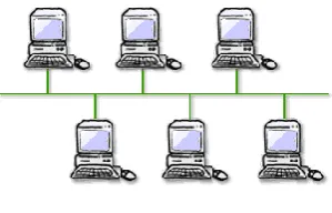
[image:2.595.322.537.72.215.2]Typically the range of a wired network is within a 2,000-foot-radius. The disadvantage of this is that data transmission over this distance may be slow or nonexistent. The benefit of a wired network is that bandwidth is very high and that interference is very limited through direct connections. Wired networks are more secure and can be used in many situations; corporate LANs, school networks and hospitals. The biggest drawback to this type of network is that it must be rewired every time it is moved[2].
Fig: 1.1 Wired Network
1.1.1
Wired Network using Static Routing
In this routing if the link is break between nodes then rerouting is not possible. In this routing scheme there is no routing protocols used.
1.1.2
Wired Network using Dynamic Routing
In this routing if the link breaks between nodes then routing is possible from other routes. In this routing ,Distance Vector Routing Protocol is used.1.2
Wireless Network
[image:2.595.81.231.246.342.2]An ad-hoc network is a collection of wireless mobile hosts forming a temporary network without the aid of any stand-alone infrastructure or centralized administration. Mobile Ad-hoc networks are organizing and self-configuring multihop wireless networks where, the structure of the network changes dynamically. This is mainly due to the mobility of the nodes. Nodes in these networks utilize the same random access wireless channel, cooperating in a friendly manner to engaging themselves in multihop forwarding. The nodes in the network not only act as hosts but also as routers that route data to/from other nodes in network[1].
Fig 1.2. Mobile Ad-hoc network.
In mobile ad-hoc networks where there is no infrastructure support as is the case with wireless networks, and since a destination node might be out of range of a source node transmitting packets; a routing procedure is always needed to find a path so as to forward the packets appropriately between the source and the destination. Within a cell, a base station can reach all mobile nodes without routing via broadcast in common wireless networks. In the case of ad-hoc networks, each node must be able to forward data for other nodes. This creates additional problems along with the problems of dynamic topology which is unpredictable connectivity changes[3].
A wireless network, which uses high-frequency radio waves rather than wires to communicate between nodes, is another option for home or business networking. Individuals and organizations can use this option to expand their existing wired network or to go completely wireless. Wireless allows for devices to be shared without networking cable which increases mobility but decreases range. There are two main types of wireless networking; peer to peer or ad-hoc and infrastructure[8]. (Wi-fi.com)
2.
Techniques for Network Performance
Evaluation
Performance is a key criterion in the design, procurement, and use of computer systems. Computer systems professionals such as computer systems engineers, scientist, analysts and users need the basic knowledge of performance evaluation techniques as the goal to get the highest performance for a given cost. There are three techniques for performance evaluation, which are analytical modeling, simulation and measurement. Simulation had being chosen because it is the most suitable technique to get more details that can be incorporate and less assumption is required compared to analytical modeling. Accuracy, times available for evaluation and cost allocated for the thesis are also another reason why simulation is chose. By using simulation, researchers should be allowed to study a system in well-known conditions, repeatability if necessary in order to understand events[12].
2.1
Computer Network Simulation Tools
There are many simulators such as Network Simulator 2(NS-2), OPNET Modeler, GloMoSim, OMNeT++ and etc. In this project we choices network simulation tool NS2. Figure 2.1 shows the basic architecture of NS2. NS2 provides users with an executable command ns which takes on input argument, the name of a Tcl simulation scripting file. Users are feeding the name of a Tcl simulation script (which sets up a simulation) as an input argument of an NS2 executable command ns. In most cases, a simulation trace file is created, and is used to plot graph and/or to create animation. NS2 consists of two key languages: C++ and Object-oriented Tool Command Language (OTcl). While the C++ defines the internal mechanism (i.e., a backend) of the simulation objects, the OTcl sets up simulation by assembling and configuring the objects as well as scheduling discrete events (i.e., a frontend). The C++ and the OTcl are linked together using TclCL. Mapped to a C++ object, variables in the OTcl domains are sometimes referred to as handles. Conceptually, a handle (e.g., n as a Node handle) is just a string (e.g.,_o10) in the OTcl domain, and does not contain any functionality. Instead, the functionality (e.g., receiving a packet) is defined in the mapped C++ object (e.g., of class Connector). In the OTcl domain, a handle acts as a frontend which interacts with users and other OTcl objects. It may defines its own procedures and variables to facilitate the interaction. Note that the member procedures and variables in the OTcl domain are called instance procedures (instprocs) and instance variables (instvars), respectively[12].
Fig-2.1 Basic architecture of NS2
NS2 provides a large number of built-in C++ objects. It is advisable to use these C++ objects to set up a simulation using a Tcl simulation script. However, advance users may find these objects insufficient. They need to develop their own C++ objects, and use a OTcl configuration interface to put together these objects. After simulation, NS2 outputs either text-based or animation-based simulation results. To interpret these results graphically and interactively, tools such as NAM (Network AniMator) and XGraph are used. To analyze a particular behavior of the network, users can extract a relevant subset of text-based data and transform it to a more conceivable presentation[11][12].
2.2
Advantage and Disadvantage of NS2
Advantages
Cheap- Does not require costly equipment
Complex scenarios can be easily tested.
Results can be quickly obtained – more ideas can be tested in a smaller time frame.
Supported protocols
Supported platforms
Modularity
Popular
Disadvantages
Real system too complex to model. i.e. complicated structure.
Bugs are unreliable
3.
Traffic Scenario for wired and wireless
network
3.1
Traffic Scenario for wired network
using TCL scripts
In this network we create a wired network traffic scenario by using tcl scripts which consist
Four nodes
Delay of 10 ms
Bandwidth of 7 Mb
Data transfer between node 1 to 2 using UDP agent and node 1 to 0 using TCP agent
TCP,UDP Agents
CBR, FTP Application
3.1.1
Static Wired Network
In this routing if the link is break between nodes then rerouting is not possible. In this routing scheme there is no routing protocols used. When we generated a static wired network ,on simulation traffic flows from one node to desired destination.
Snapshot-1
But when a link then there is no rerouting generated. Packet transfer failed from one node to other.
Snapshot-2
3.1.2
Dynamic Wired Network
In this routing if the link breaks between nodes then routing is possible from other routes.
Distance Vector Routing Protocol is used.When we generated a Dynamic wired network ,on simulation traffic flows from one node to desired destination.
But when a link break then there is rerouting possible , it adopted other path and Packet transfered from one node to other.
Snapshot-4
3.2
Traffic scenario for wireless network
using TCL scripts
In this network we create a wireless network traffic scenario by using tcl scripts which consist
Four nodes
DSDV Routing Protocol
Data transfer between node 1 to 3 using UDP agent and node 0 to 2 using TCP agent
TCP,UDP Agents
CBR, FTP Application
In Mobile Ad-hoc networks are organizing and self-configuring multihop wireless networks where, the structure of the network changes dynamically.
4.
Performance Analysis of ZRP and Tora
In wireless network we used so many routing protocols. In this paper we shown how we can calculated the performance of routing protocols by using trace file and awk scripts. The performance of two routing protocols ZRP and TORA are evaluated based on the two performance metrics which are
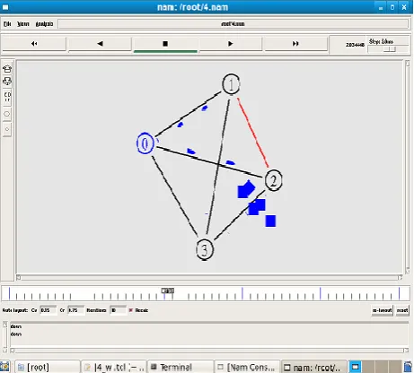
[image:5.595.55.286.115.323.2]1. Packet delivery fraction 2. Average End to End delay
Fig:4.1 A Screenshot of TORA NAM window (20 Nodes) In the given figure, 0 to 19 are the no of wireless nodes. TORA routing protocol is applied to the given scenario with different parameters. The given figure shows the NAM window at 0 time.
[image:5.595.314.544.172.409.2] [image:5.595.71.282.545.745.2]automatically generated after the complete animation in NAM window. With the help of trace file we are going to analyze our data.
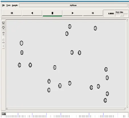
Fig:4.3 A Screenshot of ZRP NAM window (20 Nodes)
In the given figure 8.15, 0 to 19 are the no of wireless nodes. ZRP routing protocol is applied to the given scenario with different parameters. The given figure shows the early stage of the NAM window at 0 time.
Fig:4.4 A Screenshot of Trace File of ZRP window (20 Nodes)
Figure shows the trace file for ZRP. It is automatically generated after the complete animation in NAM window. With the help of trace file we are going to analyze our data.
5.
RESULT AND DISCUSION
5.1
Comparison of TORA & ZRP with
Graphs
Graph 1: Packet Delivery Ratio vs Pause Time
According to the graph TORA & ZRP on the bases of Packet delivery fraction, ZRP has some constant rate for packet delivery fraction as compared to TORA.
Graph 2: Average End to End Delay vs No. of Nodes
According to the graph average end to end delay vs no. of nodes of TORA & ZRP. Comparison is done b/w the two routing protocols. For this seven different scenarios for both the protocols had been generated with different number of nodes. According to the graph, ZRP has higher delay then TORA. For both protocols, the delay increases with the increase in the number of nodes.
5.2
Discussion
[image:6.595.53.280.135.342.2] [image:6.595.315.538.388.563.2]Ad-hoc networks are self-organizing and self-configuring multihop wireless networks where, the structure of the network changes dynamically. In wireless network we used so many routing protocols then we analyzed the performance of wireless routing protocols by the help of ns2 Simulator using TCL scripts, NAM animator. By the help of trace file and awk scripts we plot the graphs. For both protocols we increased the pause time and no of nodes. We analyzed ZRP has some constant rate for packet delivery fraction as compared to TORA and ZRP has higher delay then TORA.
6.
REFERENCES
[1] Dow, C. R, (March 2005) A Study of Recent Research Trends and Experimental Guidelines in Mobile Ad-Hoc Networks, In: Proceedings of 19th International Conference on Ad-vanced Information Networking and Applications, IEEE, Vol. 1, pp. 72-77.
[2] Freisleben, B., Jansen, R, (1997) Analysis of Routing Protocols for Ad hoc Networks of Mobile Computers, In: Proceedings of the 15th IASTED International Conference on Applied Informatics, IASTED-ACTA Press, pp. 133-136, Innsbruck, Austria.
[3] Royer, E. M. , Toh, C. K, (April 1999) A Review of Current Routing Protocols for Ad hoc Mobile Wireless Networks, IEEE Personal Communications Magazine, pp. 46-55.
[4] Anastasi, G., Borgia, E., Conti, M., Gregori, E, (2003) IEEE 802.11 Ad-hoc Networks: Protocols, Performance and Open Issues, Ad hoc Networking. IEEE Press Wiley, New York.
[5] Arun Kumar, B. R., Reddy, Lokanatha C., Hiremath, Prakash S, (January-June 2008) A Survey of Mobile Ad hoc Network Routing Protocols, Journal of Intelligent System Research.
[6] C. Siva Ram Murthy and B.S. Manoj. Ad Hoc Wireless Networks, Architecture and Protocols, Pearson Education, 2004
[7] Charles E. Perkins, Elizabeth M. Royer, Samir R. Das and MLahesh K. Marina, Performance Comparison of Two On-Demand Routing Protocols for Ad Hoc Networks, IEEE Personal Communications, February 2001 [8] Charles E. Perkins. Ad Hoc Networking, Addison-Wesley,
2001
[9] Charles E. Perkins & P. Bhagwat, Highly Dynamic Destination-Sequenced Distance Vector Routing (DSDV) for Mobile Computers, Proceedings of ACM SIGCOMM'94, London, UK, Sep. 1994
[10] Royer, E. M. , Toh, C. K, A Review of Current Routing Protocols for Ad hoc Mobile Wireless Networks, IEEE Personal Communications Magazine, pp. 46-55, April- 1999.
[11] Anil Kumar Verma, Dr. Harsh Sadawarti, Performance analysis of AODV, DSR and TORA routing protocols, IACSIT,Vol.2, No.2, ISSN :1793-8236, pp.226-231, April 2010.