ABSTRACT
Mobile communication towers are used in many personal and industrial purposes. It provides a continuous connectivity to Mobile Nodes (MN) and permits them to change their connection point from current access point to new base station while needed. Handover has become an essential part in mobile communication system because of the limited coverage area of cells. Handover of calls between two cells is encountered and it is required to minimize the delay of the process. In this paper, the horizontal distance measurement using Global Positioning System (GPS) approach is used where hexagonal cell is divided in four quadrant having angle of 90o to each quadrant. Calculating distance of moving mobile node towards boundary („m‟) by GPS and comparing with the point („n‟) at which handover is initiating, then angle (θ) is calculated with respect to position of MN to select potential next station.
Keywords
Access Point, Base station, GPS, Mobile Node
1. INTRODUCTION
In recent years, Wireless Local Area Network (WLAN) with wide bandwidth and low cost has been changed as a competitive technology to settle in the user with strong desire for mobile computing. Nowadays mobile stations (MS) are equipped with multiple radio interfaces for connecting to different wireless networks. The major problem on mobile computing is handover management between access point and base station [1]. For real-time multimedia service like voice over IP (VoIP), the problem of handover delay has to be resolved. To solve this problem, many techniques are proposed by developing new algorithms. Their approaches are broken into three different categories including network layer (L3), data link layer (L2), and physical layer (PHY).
1.1 Handover
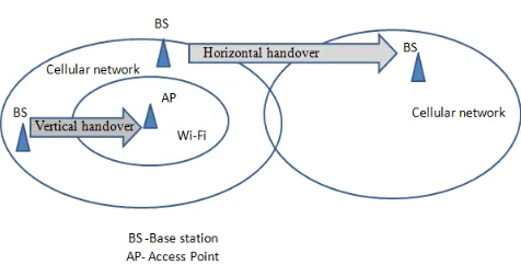
[image:1.595.320.558.221.342.2]When a MS moves away from its current AP, it must be reconnected to a new one to continue its operation. The search for a new AP or base station (BS) and following registration without any loss is known as handover and the time required to complete a handover process is known as handover latency. Figure 1 shows the scenario of horizontal and vertical handover.
Figure 1: Horizontal and Vertical handover
1.1.1 Horizontal Handover:
A mobile node moves withthe single network from one AP or BS to the other one is called as „Horizontal handover‟. For Example, mobile node is moving from AP of WiFi network to AP of same network.
1.1.2 Vertical Handover:
A mobile node moves with the different network that is from one BS to the other AP or BS of another network is called as „Vertical handover‟. Example is AP of WiFi network to BS of Cellular network and vice versa.1.2
GPS System
The Global Positioning System is a satellite based system that is used to establish positions anywhere on earth. GPS is a collection of satellites that are continuously orbiting the earth. These satellites, which are combined with atomic clocks, transmit radio signals that include their exact location, time, and other information. The signals of radio from the satellites, which are observed, monitored and corrected by control stations, and are picked by the GPS receiver. A GPS receiver needs only three satellites to plot a rough, 2D position. Four or more satellites are needed to plot a 3D position, which is more accurate.
2. RELATED WORK
Mobile stations move from one cell to another cell in wireless network. In each cell, it is required to handle the communication of the mobile station. When it changes its cell, time is required to select potential access point or base station and to transfer information of mobile station to the new cell of access point or base station according to networks present. This information is transferred with the help of number of packets. So, a delay is introduced during the handover in
Reduction of Handover Latency by Horizontal
Distance Measurement using GPS
Ashwini Misal
Santosh Sambare
Department of Computer Engg. Department of Computer Engg. Pimpri Chinchwad College of Engg. Pimpri Chinchwad College of Engg.
types of delay. In [2] When a mobile node or station setup call it scans channel only once and calculate scanning time as Ts. As soon as MN tries to associate new potential AP, it calculates the distances of mobile node from old AP as S by using GPS and velocity V of the MN. Then it calculates the time before handover that is T = S/V and also calculates a factor N = T/Ts. So, when N is equal to or less than 1, the MN starts scanning and gets all the potential APs before the actual handover is triggered. With this scheme, probe delay is reduced in the handover procedure. In [3], Handoff Minimization using cell sectoring method, in which a cell is divided in three sectors and thus reduces the number of APs to be scanned by fixing the neighbor APs with respect to each sector. Thus, here two APs are fixed for each sector. MS will choose the nearest one out of two APs. In [4] distance measurement method they propose a new scanning method where it determine distance of nearest AP from MN to bypass the main process. In [5] authors proposed a pre-scanning scheme using Neighbor graph cache memory. If MN has T time before handover, and scanning time is Ts. Then total no of times cache is updated with neighbor graph is n=T/Ts. Scanning delay in this mechanism depends upon n. If the probability of n being an integer is greater, that is minimum delay.
3. PROPOSED METHOD
[image:2.595.335.552.394.532.2]Horizontal distance measurement (HDM) method reduces total handover delay. In this paper, WiMAX and WiFi these two networks are considered for handover. The hexagonal cell is divided into 4 sectors (Quadrants) with each sector having an angle of 90o as shown in the Figure 2. GPS finds out the positions of MS according with its moving direction i.e. in which quadrant it is operating.
[image:2.595.74.284.423.559.2]Figure 2: Cell sectoring with quadrant for Hexagonal cell
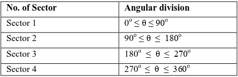
TABLE 1: Angles with different quadrant
No. of Sector Angular division
Sector 1 0o ≤ θ ≤ 90o
Sector 2 90o ≤ θ ≤ 180o Sector 3 180o ≤ θ ≤ 270o Sector 4 270o ≤ θ ≤ 360o
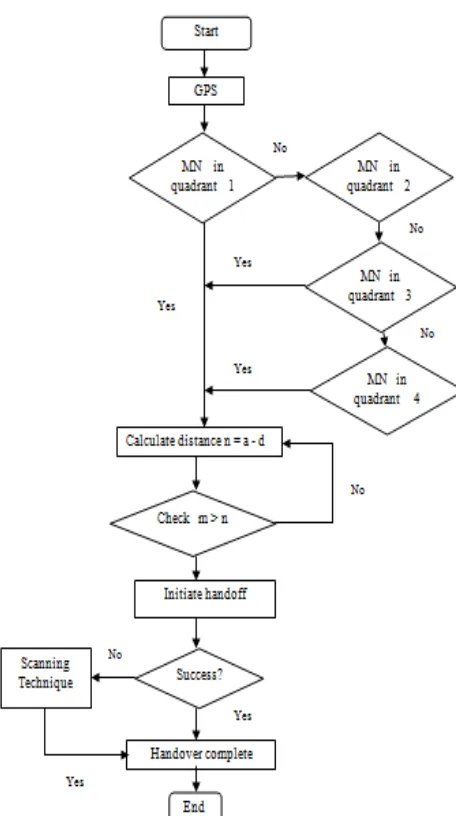
Proposed algorithm is as following.
1. After call setup of mobile node, GPS find co-ordinates of MN
2. Decide the quadrant according to position of MN
3. Calculate moving distance of MS (m) from centre of old AP 3.1 Calculate n = a - d for each and every movement of MS (n - point at which handoff is to be initiate, a- hexagonal side, d- handoff region.)
3.2 If m ≥ n MS starts scanning selectively and jump to step 4
3.3 Else jump to 3.1 4. Authenticate with new AP 5. Re-associate with new AP /*Handoff complete*/
The potential AP or BS searches can be made up to a certain distance after which the MN performs the handover process. The distance„d‟ which is required in order to carry out the remaining portion of the handover procedure is given by the equation: d = v × tdelay.
n- Point to initiate handover
m - Moving Distance of mobile node (MN)
θ - Angular Displacement
d - Handover region
[image:2.595.50.284.586.662.2]Figure 4: Flowchart for handover algorithm.
The AP has 4 quadrants with X and Y axis as shown in Figure 3. The initial coordinate of the MN be (x, y). Moving distance of MN is calculated to check its probability to initiate handover without fail. If mobile node is reached at the point where handover is to be initiate, the angular displacement (Ө) of mobile node is calculated as following,
(1) If x > 0 and y > 0 then Ө = arctan(y/x)
(2) If x < 0 and y > 0 then Ө = 180○ – arctan (|(y/x)|) (3) If x < 0 and y < 0 then Ө = 180○
+ arctan (|(y/x)|) (4) If x > 0 and y < 0 then Ө = 360○ – arctan (|(y/x)|)
So from the value of Ө, the neighbor potential access point or base station is selected to give progress to a call. Scanning delay is calculated as
‟×ґα
4. SIMULATION RESULTS
Proposed algorithm is simulated to test its functionality. The MN follows a random trajectory and after a certain time moves towards the boundary of the cell. At the end of the algorithm the angle is noted at which the MN moving towards handover region of distance„d‟. All the coordinates are in meters and are measured in reference to the present base station as the origin and axis shown as in Figure 3. After simulation of proposed algorithm the average speed is recorded as 33m/s. The average handover delay of previous proposed paper is taken as 0.064s [3]. The moving distance „m‟ of mobile node calculated by GPS is compared with distance „n‟. Here „n‟ is calculated as difference of hexagonal side ‟a‟ and handoff region„d‟.
[image:3.595.310.549.308.442.2]After simulation the status of moving node is shown in TABLE 2 with its co-ordinates, distance and speed of MN. Distance is calculated from the centre of the cell. X and Y co-ordinates shows the position of moving mobile node. The speed of moving mobile node is calculated at different state. The average of speed is used to calculate handoff region area.
TABLE 2: Result of Moving status of Mobile node
[image:3.595.309.544.540.676.2]The distance 1997.90m at which handoff is initiating, the angular displacement is calculated for position of mobile node. After checking handover initiating condition, angular displacement of mobile node for that position is calculated as 135.35o in second quadrant. MN is moving towards BS3. After selecting the potential base station the MN gets authenticated and re-associated with new BS.
TABLE 3: Result for different handover scenario
Sr. No.
Wi-Fi Networ k(2.4G H)
WiMAX Network (20MHz)
Base Paper (Delay)
HDM (Delay)
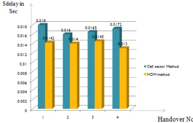
1 WF_6 WM_4 0.01788s 0.01539s
2 WF_1 WM_5 0.01774s 0.01550s
3 WF_3 WM_6 0.01906s 0.01568s
4 WF_4 WM_3 0.01862s 0.01528s
Average Delay
0.01832s 0.01546s
The cell sectoring method [3] is implemented for scanning and total handover delay. The proposed HDM method is also simulated for different handover scenario and results are
Sr. No.
X(axis) Y(axis) Distance(m) Speed(m/s)
1 -148.78 0.0 148.78 33.57
2 -481.37 0.0 481.37 33.50
3 -875.23 875.23 556.62 33.55
with BS(4,5,6,3) of Wi-MAX network. The average total handover delay of HDM method is calculated as 0.01546s. Figure 5 shows different handover scenario result of scanning delay and compared with existing system [3]. Figure 6 shows the total delay is reduced as compared to existing system. Result shows that proposed algorithm is reducing scanning and total handover delay efficiently.
[image:4.595.57.272.307.468.2]Figure 5: Comparative graph of scanning delay
Figure 6: Comparative graph of total handover delay
5. CONCLUSION AND FUTURE SCOPE
This proposed method reduces handover delay by reducing the number of access point or base station to be scanned which is accomplished by cell dividing in 4 quadrant and distance measurement with help of GPS. The angle θ made with X axis gives direction of potential AP where MS has to move in new network. In this method, moving distance of MS using GPS is calculated to check whether it is present in handover region or initiate handoff. Scanning is occurring before handoff that gives less probability of failing the handoff. Total delay of proposed algorithm is improved efficiently by 15%.Proposed approach can be improved by dividing the hexagonal cell in more sectors and verify the results which may reduce handoff delay. The ping pong effect of MS may reduce effectively using new technique.
6. REFERENCES
[1] “Wireless LAN Medium Access Control (MAC) and Physical Layer (PHY) Specifications,” IEEE Standards, 1999.
[2] Debabrata Sarddar, Joydeep Banerjee, Jaydeep Ghosh Chowdhury,Ramesh Jana, Kaushik KumarNundy, Utpal Biswas, M.K.Naskar „Reducing handover delay by pre-selective scanning using GPS‟ International Journal of Distributed and Parallel Systems (IJDPS) Vol.1, No.2, November 2010.
[3] Debabrata Sarddar et al. „Minimization of handoff latency by cell sectoring method using GPS‟ International Journal of Computer Applications (0975 – 8887)
[4] Debabrata Sarddar et al. „Minimization of handoff latency by Distance measurement method‟ International Journal of Computer Science Issues, Vol. 8, Issue 2, March 2011
[5] D. Sarddar, T. Jana, K. Mandal, T. Patra, U. Biswas, Prof. M.K. Naskar. “Pre-scanning mechanism to reduce handoff latency with the help of Neighbor Graph”. [6] Vishal Agarwal et al. “Handoff latency minimization by
Relative Distance Method” International Journal of Emerging Technologies in Computational and Applied Sciences, 3(2), Dec.12-Feb.13, pp. 123-127.
[7] J. Pesola and S. Pokanen, „Location-aided Handover in Heterogeneous Wireless Networks‟, in Proceedings of Mobile Location Workshop, May 2003.
[8] Chaegwon Lim Dong-Young Kim Osok Song Chong-Ho Choi „SHARE: seamless handover architecture for 3G-WLAN roaming environment‟ Springer Science+Business Media, LLC 2007.
[9] Debabrata Sarddar, Joydeep Banerjee, Tapas Jana, Souvik Kumar Saha, Utpal Biswas, M.K. Naskar “Minimization of Handoff Latency by Angular Displacement Method Using GPS Based Map”, IJCSI International Journal of Computer Science Issues, Vol. 7, Issue 3, No 7, May 2010 , pp. 29 – 38.
Comments Modification 1. More comprehensive evaluations are needed. Authors should
present the corresponding analysis in detail supported by graphical
and tabular data. Details of graphical and tabular data are added. Page no. 2, 4
2. The text labels in all the figures used in the paper are unclear. Authors must develop original image/figures with high resolution
for proper rendering of the final published paper and should not distort on zooming. The text labels in the images must be clearly visible.
Labels of figures cleared. Changes done on page no. 3, 4
3. Image format of the tables is not acceptable. The text labels in all the tables used in the paper are unclear. Author can use Microsoft Office tools to create the tables. The text labels in the
tables must be clearly visible. Image format of table get changed. Page no. 4
4. Conclusion needs to be elaborated mentioning the future scope of the idea.