A static model of a Sendzimir mill for use in shape control.
GUNAWARDENE, G. W. D. M.
Available from Sheffield Hallam University Research Archive (SHURA) at:
http://shura.shu.ac.uk/19734/
This document is the author deposited version. You are advised to consult the
publisher's version if you wish to cite from it.
Published version
GUNAWARDENE, G. W. D. M. (1982). A static model of a Sendzimir mill for use in
shape control. Doctoral, Sheffield Hallam University (United Kingdom)..
Copyright and re-use policy
See http://shura.shu.ac.uk/information.html
!
* v n u J iiv iiiii I _ _ SHEFFIELD S I 1VVB |jJ^QO
79294
-64
-0
, ,6Sheffield City Polytechnic Library
REFERENCE ONLY
ProQuest Number: 10697036
All rights reserved
INFORMATION TO ALL USERS
The quality of this reproduction is dependent upon the quality of the copy submitted.
In the unlikely event that the author did not send a com plete manuscript and there are missing pages, these will be noted. Also, if material had to be removed,
a note will indicate the deletion.
uest
ProQuest 10697036
Published by ProQuest LLC(2017). Copyright of the Dissertation is held by the Author.
All rights reserved.
This work is protected against unauthorized copying under Title 17, United States C ode Microform Edition © ProQuest LLC.
ProQuest LLC.
789 East Eisenhower Parkway P.O. Box 1346
STATIC MODEL OF A SENDZIMIR MILL
FOR USE IN SHAPE CONTROL
BY
G W D M GUNAWARDENE MSc
A thesis submitted in partial fulfilment of the requirements of the Council for National Academic Awards for the Degree
of Doctor of Philosophy (Ph D)
Department of Electrical and Electronics Engineering
Sheffield City Polytechnic Pond Street
Sheffield
Collaborating bodies : British Steel Corporation Swindon House
Rotherham S60 3AR
GEC Electrical Projects Ltd Boughton Road
Rugby
A STATIC MODEL OF A SENDZIMIR MILL FOR USE IN SHAPE CONTROL
by
G W D M GUNAWARDENE MSc
ABSTRACT
The design of shape control systems is an area of current interest in the steel industry. Shape is defined as the internal stress distribution resulting from a transverse variation in the reduction of the strip
thickness. The object of shape control is to adjust the mill so that the rolled strip is free from internal
stresses. Both static and dynamic models of the mill are required for the control system design.
The subject of this thesis is the static model of the Sendzimir cold rolling mill, which is a
1-2-3-4 type cluster mill. The static model derived
enables shape profiles to be calculated for a given set of actuator positions, and is used to generate the steady state mill gains. The method of calculation of these shape profiles is discussed. The shape profiles obtained for different mill schedules are plotted against the
DECLARATION
ACKNOWLEDGEMENTS
This thesis, being the result of three years of research work, naturally involves the co-operation, consultation and discussion with many people. I wish to express my gratitude to everybody concerned.
I wish to thank my supervisor and the project leader Prof. M. J. Grimble for his guidance and encouragement throughout this research work, and also to my second supervisor Dr. G. F. Raggett of the Department of rfethematics for his valuable assistance.
I would specially like to thank Dr. A. Thomson of GSC Electrical Projects Ltd., whose advice was invaluable and to Mr. K. Dutton of BSC.
FOR USE IN SHAPE CONTROL
G ¥ D M G U N A WARDENE MSc ABSTRACT
The design of shape control systems is an area of current interest in the steel industry. Shape is defined as the internal stress distribution resulting from a transverse variation in the reduction of the strip thickness. The object of shape control is to adjust the mill so that the rolled strip is free from internal stresses. Both static and dynamic models of the mill are required for the control system design.
The subject of this thesis is the static model of the Sendzimir cold rolling mill, which is a
1-2-3”^ type cluster mill. The static model derived enables shape profiles to be calculated for a given set of
CONTENTS.
DECLARATION
ACKNOWLEDGEMENTS i
ABSTRACT ii
CONTENTS iii
1 INTRODUCTION
1.1 Review of the history of rolling mills 1
1.2 The purpose of rolling mill research 3
1.3 The Sendzimir cold rolling mill 5
1.4 Shape control problem 8
1.5 Objectives and summary of presentation 11
2 THE SHAPE CONTROL IROBLEM
2.1 Introduction 15
2.2 Definition and units of shape 17
2.3 Shape measuring devices 19
2.4 Shape control mechanisms 21
2.5 Disturbances to shape 22
2.6 Interaction between shape and gauge 23
2.7 Description of the mill 23
2.8 Elementary shape control scheme 26
2.9 Purpose of the study 27
3 THE STATIC MODEL
3.1 Introduction 39
3.2 Roll bending calculation 42
3.3 Roll flattening calculation 43
3.4 Roll force calculation 46 3.5 Output gauge and shape profile
calculations 48
3.6 Brief description of the static model
computer algorithm 50
Chapter 4 COMPLETE STATIC MODEL ALGORITHM
4.1 Introduction 54
4.2 Strip width adjustment 55
4.3 Strip dimensions 55
4.4 Back-up roll profile 57
4.5 First intermediate roll profile
calculation 60
4.6 Static forces in the mill cluster 6l
4.7 Elastic foundation constant K 62
4.8 Roll force model 65
4.9 Inter roll pressures 67
4.10 Roll deflections 71
4.11 Strip thickness and stress profiles 74
4.12 Pressure and deflection profiles for
one quarter of the mill cluster 78
4.13 Mill gain matrix 82
Chapter 5 STATE SPACE REPRESENTATION OF THE MILL
5.1 Introduction 103
5.2 Mill representation in state space form 106 5*3 State equation of the complete system 115
5.4 Shape profile parameterisation 118
5.5
Chapter 6
6.1
6.2
6.3 6.4 6.56.6
Chapter 7
7.1 7.2 7.3 7 > REFERENCES BIBLIOGRAPHY APPENDIX 1 APPENDIX 2 APPENDIX 3 APPENDIX 4 APPENDIX 5 APPENDIX 6
APPENDIX 7
Shape control system design 121
RESULTS AND DISCUSSION OF RESULTS
Properties of shape profiles 130
Properties of the mill gain matrix 132
Shape changes for strip width variation 135 The effect on gains of changing other
variables 138
Shape control system diagonalisation
using singular value decomposition 142
Gain matrices for different schedules 149
CONCLUSIONS
General conclusions 212
Shape profiles and static gains 215
Shape control design 218
Future work 221
223
230
Forces in the roll gap 235
Theory on elastic foundations 24l
Actuator transfer function gains 250
Strip dynamics 252
Shapemeter time constants 254
Mill transfer functions for low,
medium and high speeds 255
Yield stress curve for stainless steel
type 304 256
Errata
p45 Line -9 Replace "eq.(3.6)” by ”eq.(3.7)"
p71 Eq. 4.53 Replace ” q = ... = q(x)” by "cf = ..
p76 Eq. 4.65 Replace "h^
Q
h ..." by "hnft
p83 Eq. 4.89 Replace the limits by "M x
d97 Fig 4.14 2nd box should read y . = f(F.(x), a,a J J
p124 Line -5 Replace "U^ and V ” by "V and l)"^"
p129 Fig 5.5 Replace "V" by "U^*” and "U” , by
□140 Line 11 Replace "decrease" by "increase" Line 12 Replace "0^ to O
2
" to "0^ to 02"■ = q ( * )
vv
( i-1) "
b )
[image:14.622.42.556.71.743.2]Chapter 1.
INTRODUCTION.
1.1. Review of the history of rolling mills.
First evidence of a possible attempt to design a cold rolling mill appears in a sketch by
Leonardo da Vinchi1. The machine was built later to stretch and roll copper strips of sufficient evenness and thinness, for the making of mirrors. The history of rolling records the construction of a hand mill for lead rolling in 1615. Nearly a century later there were various plate mills
powered by water wheels or horses for rolling lead and copper. By around 1700, reasonably large mills were in operation for rolling hot ferrous metals. The idea of the three - high mill for rolling metal was more than a
century old before it was first introduced into iron works in Sweden in 1856 and in England in 1862. Its inventor, Christopher Polheim had realised the value of being able to pass the metal back and forth without having to reverse the rolls.
Another idea from the previous century, the continuous mill, had been patented by William Hazeldine in 1798, but was not used until it was reinvented by George Bedson in 1862. Here the metal was fed successively into a series of roller stands placed in line so that its size was reduced.3
-The development of rolling mills has continued at a high increasing rate from 1920*s onwards. Today there are a wide range of mill configurations and associated
equipment to suit all applications. The period of greatest evolutionary change, which spans the last fifty five years,
can be divided into three distinct periods: first generation mills from 1927 to i960, second generation from 1961 to I969 and third generation from 1970 to present day!
Up to i960, strip mills operated at low speeds (with exit speeds not more than 12 m/s) and handled small coils weighing up to about 10,000 kg. From i960 the
progress was rapid and the second generation mills were designed to deal with heavier coils and at faster speeds. By the end of the decade automatic gauge control was
introduced to meet the more demanding market. The third generation mills emerged in response to the need to roll much larger coils. These mills were capable of handling 45,000 kg coils at speeds up to about 29 m/s.
Major requirements of rolling may be outlined
as increasing coil sizes, gauge and shape performance, and led to many new developments. These include the introduction of more stands per tandem mill, improved automatic gauge control systems, hydraulically loaded mills, automatic roll changing, strip threading and coil stripping facilities and continuous rolling.5
-The development of computers helped the automation of tandem mills. The first computer controlled mill was commissioned at British Steel Corporation, Port Talbot, England in 1964. This was followed by a chain of developments of computer controlled mills, with the objective of obtaining good shape and accurate gauge. The subject of automatic gauge control and shape control became more
important in computer control development with the application of shape measuring devices6.
1.2. The purpose of rolling mill research.
Rolling first started with hot materials, with the knowledge of how to obtain a desired result. In many cases the reasons were unknown and the practical knowledge was more advanced than the theory. Weaknesses and defects of rolling were discovered through failures, and succesful designs were produced by improving the faulty parts. This experience of success through failure stimulated the
understanding of rolling, such as what happened to a material when it passed between rolls, what forces were required to deform it, etc. The knowledge was needed by the designer to estimate, for example, the stresses in his machine, and by the operator to produce his product as cheaply and efficiently as possible.
Later, when cold rolling was introduced, a new set of problems had to be faced, since the requirements of the rolling process was to produce materials reasonably flat and
-of uniform thickness across the width and length -of the material. This required that the screwdown mechanism was carefully adjusted for each pass and that the rolls were maintained in good condition with the right shape. When rolling at high speeds, the rolls became heated and lost their shape, so that temperature control of the rolls became necessary. The lubricant to use on the strip demanded further investigation, and the best type to use for a given case is still a matter for experiment.
Materials also began to be rolled in the form of very long strip, so that it had to be wound on drums driven from the mill. Front and back tensions were introduced to obtain a better product. These tensions affected the performance of the mill and suitable values had to be found by experience.
The friction forces between two rolls, and between work rolls and material cannot be directly measured.
It was found, by experience, that the pressure required to deform the material between the rolls is much greater than that needed for a similar reduction between flat frictionless plates, owing to the friction effects. It was also found that the pressure varies with the thickness of the material. Vertical plane sections of the material
became distorted in an almost unpredictable manner and the material was found to spread laterally in addition to the longitudinal spread. The amount of spread was found to be
-dependent not only on the dimensions and type of material used, but also on the diameter and surface conditions of the rolls, rolling speed, etc. To understand these it was necessary to develop the mathematics of rolling.
In addition to these, new materials, higher outputs, lower rolling costs, better products with uniform gauge, etc., demand more knowledge of the principles
underlying rolling. The functions of rolling mill research are to provide this knowledge and to show the ways of
improvement!
1.3. The Sendzimir cold rolling mill.
The Sendzimir cold rolling mill has achieved recognition throughout industry in rolling ferrous and
g
non-ferrous metals. Sendzimir mills axe cluster mills and they differ fundamentally from conventional mills. This fundamental difference is the way in which the roll separating forces are transmitted from the work rolls, through the intermediate rolls to the back-up assemblies, and finally to the rigid housing. As this design permits the support of the work rolls throughout their length,
deflection is minimised and extremely close gauge tolerances can be acheived across the full width of the material
being rolled. In comparison to Sendzimir mills, the rigidity of conventional mills is governed by the size of the work rolls and the back-up rolls, which are supported by their
-necks in two separate housings. Under rolling pressures this results in roll deflection and therefore thickness variation, especially near the centre of the strip.
The housing of Sendzimir mills is designed to deflect uniformly across the entire width of the mill. It provides continuous backing to the roll cluster and has the heaviest cross section at the centre of the mill where the forces are greatest. It also has short heavy columns to carry the roll separating forces which makes the mill very rigid. This makes it possible to produce strips with extremely close tolerances across and throughout the length.
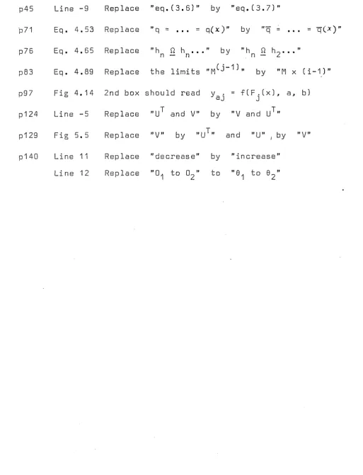
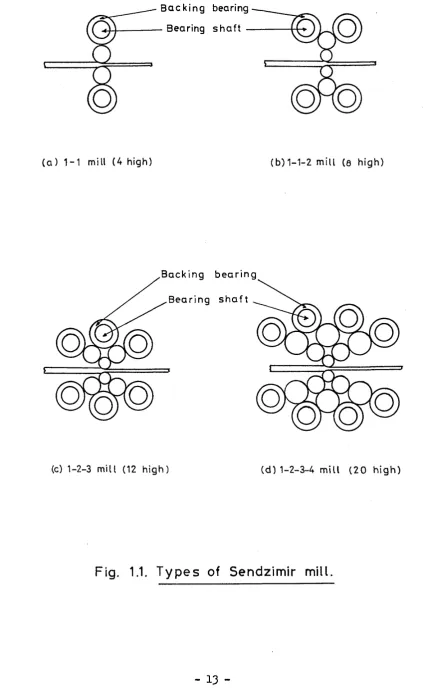
All bearing shafts (see fig.l.l) of Sendzimir mills have concentrically mounted roller bearings and are located eccentrically in saddles. A cross section of one is shown in fig. 1.2. By rotating the bearing shafts, the position of the backing bearings can be changed with respect to the housing, to closely control the distance between the work rolls. This is the basic control movement of the mill that permits accurate positioning of its rolls. A detailed description is given in section 2.7.2.
On Sendzimir mills crown control adjustment operates on the top backing bearings. It is known as "As-U-Roll" crown adjustment and is actuated hydraulically from the operator's desk while the mill is running. As-U-Roll operation is described in detail in section
2.7.3.
-Another feature of Sendzimir mills is the capability of using small work rolls. Small work rolls are subject to less flattening and can continue to reduce
metal even after it has become work hardened and very thin. This means that the mill is capable of rolling harder metals without intermediate annealing. Another
advantage of the small rolls is that tungsten carbide rolls can be used economically. Rolls of this material produce high standard surface finish and maintain it over long production runs. Small rolls can be changed very easily and quickly so that strip of various widths and finishes can be rolled without stopping the mill for long periods of time.
On Sendzimir mills, lateral adjustment of the first intermediate rolls provide a means for rolling strip of various widths with a minimum of set up time, (see section 2.7.4). These intermediate rolls are furnished with tapered ends and this exclusive feature adds greatly to the flexibility of the mill.
When rolling materials like stainless steel the rolls and the strip get extremely hot due to friction effects. Recirculating coolant is used to lubricate and cool the roll gap, rolls and backing bearings of the mill. The main cooling of the mill is done at the roll gap by
using high pressure sprays. In general, the flow of the lubricant is directed from the centre to the outside edges
-of the strip so that the lubricant would wash away any loose particles of the metal being rolled. One of the requirements for good operation of the mill is good filtration of the lubricant and good maintenance of the filters. Normally the coolant system consists of a dirty lubricant tank, pumps to send the lubricant to filters, a clean oil tank and pumps to send the lubricant to the mill.9
There are several different types of Sendzimir
10
mill and the four basic types are shown in fig. 1.1. The subject of this study is the type 1-2-3-4 Sendzimir mill which is the most powerful and most flexible. The roll cluster contains twelve rolls and eight backing bearing assemblies as shown in fig. 2.4. The type 1-2-3-4 mill also varies with size, and are used to roll different
dimension strips. In particular this study is concerned with a 1.7 m wide type 1-2-3-4 mill which is situated at British Steel Corporation Stainless, Shepcote Lane, Sheffield, England.
1.4. Shape control problem1.1"”18
Shape describes a deviation from flatness in sheet or strip of metal. The change in demand from sheet to coil experienced by wide strip produced over the past fifteen years has brought about the need for good shape to be acheived during continuous strip processing. The demands on shape for domestic products such as washing machines,
-fridges, freezers, etc., are most severe.
Shape is the second largest single cause for the rejection of cold rolled steel strip. Bad shape is often caused by the mismatch between the roll gap profile and the incoming strip thickness profile. This can
produce transverse variations in thickness (or variations in reduction of thickness across the width) which result in differential elongations across the width of the rolled strip. These differences can be accommodated only by large internal stresses within the strip which may cause local elastic buckling. Shape is related to internal stresses of the strip and shape is defined as the internal stress distribution due to a transverse variation in thickness reduction. The strip is said to have good shape when the internal stress distribution is uniform (see sections 2.1 and 2.2). Hence shape control refers to control of internal stress distribution across strip width when undergoing a thickness reduction.
The assessment of shape during rolling was simple when waves and the profile of ends could be seen in strips. The changing pattern of reflections on the
surface may allow the deviation of flatness to be detected and the effect of corrective actions to be judged. However, with increases in strip tension, speed, coolant supply and enclosure of rolling mills, the observation is often
unreliable. An instrumental method of detecting shape has
-thus became desirable and essential for closed loop control. It was only in the last fifteen years that reliable shape measuring devices have become commercially available and the situation with shape control is now rapidly changing.
It has been well known that transverse
variations in thickness are associated with bad shape and cambered rolls were used to counteract the mismatch between roll gap profile and the incoming thickness profile. It has been suggested that roll deflections should be minimised, to correct shape defects, by reducing roll force with
smaller work rolls and backing them with stiff support rolls. It has also been suggested that roll force should be maintained constant at the correct value to match camber and that thermal camber should be minimised by efficient cooling. Strips may have localised bad shape due to uneven coolant application causing hot bands on the rolls and this may be remedied using efficient coolant distribution.
Tension can correct bad shape during rolling, but its effectiveness is not prominent, and it must be kept well below the yield stress to avoid fracture. By regulating screw-down settings, tension or speed it is possible to adjust roll force and deflection, but this
action may affect the mean gauge as well as the transverse gauge variation. The resultant effect on shape is judged by the operator and he will attempt to choose a suitable
-corrective action for improving flatness as well as gauge uniformity.
One of the main obstacles for automatic
closed loop control of shape was the commercial availability of reliable shape measuring devices. In the last fifteen years this has been overcome and reliable shape meters are
available as shape monitoring element. The design of closed loop shape control systems became the current interest in the metal rolling industry.
1.5. Objectives and summary of presentation.
The first requirement in the design of a shape control system for a rolling mill is a model of the mill. Both static and dynamic models are required for this purpose. The static model is used to calculate the steady state gains which will then be used in the dynamic simulation. The main objective of this study is the
development of the mill model which represents the roll 19
cluster and the conditions within the roll gap.
The shape problem is discussed in chapter two. The definition and units of shape are given and shape
measuring devices are discussed briefly. A detailed
discription of the Sendzimir type 1-2-3-4 mill is also given.
Chapter three describes the basic foundations of the static model and in chapter four the complete
-static model algorithm is discussed. A discussion of the state space representation of the whole shape control system is also given in chapter five. The static model results are presented and discussed in chapter six and some suggestions for improvement of the model are also given.
-Backing bearing Bearing shaft
-(a) 1-1 mill (4 high) (b)1-1-2 mill (e high)
Backing bearing
Bearing shaft
(c) 1-2-3 mill (12 high) (d) 1-2-3-4 mill (20 high)
Fig. 1.1. Typ es of Sendzimir mill.
[image:27.613.99.529.34.723.2]-Eccentric ring
Backing bearing
Bearing shaft
Foot of the saddle
Fig. 1.2. Cross section of a bearing s h a ft
[image:28.612.89.475.129.715.2]Chapter 2.
THE SHAPE CONTROL PROBLEM.
2.1. Introduction.
In recent years, the problem of the control of the gauge of steel strip leaving a rolling mill, has
20
largely been solved. The major problem of current interest in cold rolling mills involves the control of internal
21— 27
stresses in the rolled strip. This is referred to as shape control, a term which often causes confusion. Strip with good shape does not have internal stresses rolled into it. When such a strip is cut into sections, they should remain flat when laid on a flat surface. Shape measurement is generally a difficult problem, since the strip is
normally rolled under very high tensions which makes the shape defects not visible to the naked eye. It is only in the last fifteen years that reliable shape measuring devices have become available and this has enabled recent work on shape control to progress to the closed loop
control stage.
To illustrate how bad shape might arise
consider a strip having an entry gauge profile of uniform thickness. Assume also that the work roll has a profile such that the diameter of the work roll at the centre is larger than at the edges (barrel shape). When a strip having uniform thickness is rolled using the work roll
-described above the reduction of thickness at the centre of strip will be greater than at the edges, assuming that there is no lateral spread. Since strip is one homogeneous mass such differential elongations cannot occur and internal stresses result. Clearly if the strip is to be flat after rolling, the reduction of thickness as it passes through the roll gap must be a constant across the strip width.
Shape may be defined as the internal stress distribution due to a transverse variation of reduction of the strip thickness. There are two types of bad shape. If a section of strip is sufficiently stiff to resist
deformation the strip may appear to have good shape, but latent forces will be released causing deformations during slitting operations. This type of bad shape is referred to as latent shape. Hie second type of bad shape is called manifest shape, where thin strip having insufficient strength to resist forces imposed, exhibits bad shape in the form of waves or ripples extending along the length of the
12
strip and covering the whole or part of the width. These two types of bad shape are illustrated in fig. 2.1.
The stress distribution patterns giving rise to bad. shape may be tensile or compressive in nature. The actual appearance of buckling will depend upon the
28
distribution of stresses and some examples of manifest shape known generally as long edge, long middle, herring bone and quarter buckle are illustrated in fig. 2.2. Long
-edge and long middle arise ftrom- fairly elementary stress configurations. As the strip thickness decreases the latent stress capacity decreases and hence manifest shape defects are more often observed. Frequently these appear in complex forms such as herring bone and quarter buckle.
Deformations such as long edge and long middle are caused by the mismatch between the strip and roll gap profiles under rolling. The factors which affect
29
strip shape may be listed as:
1. Incoming hot band strip profile,
2. Roll separating force and its effect on roll camber,
3. Strip entry and exit tensions, 4. Slip in the roll gap.
2.2. Definition and units of shape.
Shape may be defined as the internal stress distribution due to transverse variations of reduction of the strip thickness. The transverse variation in the
longitudinal stresses is caused by the transverse variations in the slip and hence the strip velocity at the exit of the stand (or at the entry to the next stand in a
multistand mill).
14
Pearson has defined a unit of shape called the •mon* in terms of the classical long edge or long middle defects. Pearson relates shape to the amount of
-bowing present in narrow bands slit from the strip. The mon defines the shape of strip which if slit into bands of 1 cm wide, would produce a lateral curvature corresponding
/f
to a radius of 10 cm. If this definition is applied to a long edge or long middle defect, the shape in mons is the fractional difference in elongation between the centre and edge of the strip multiplied by a factor of 10 . That is, let A^ represent the difference in length between the longest and shortest line segments of the strip, then
mons = — .10** (2.1)
t
For example, for 0.01 % elongation A-#/# = 0.0001 and this equals one mon unit. The strip shape may be defined as the relative length difference per unit width expressed in mortem. That is
Shape = ~r"~~ *10** modern (2.2)
I ws
where w is the width of the strip in cm. For mosts
applications a shape of 0.05 moi^cm is considered very good and a shape of 1 mon/cm is considered very bad in rolling strip.
30
Sivilotti et al define another unit for shape called I units. It is defined as
I unit = ^- 1^5 (2.3)
V
-2.3. Shape measuring devices.
The lack of a good shape measuring device for many years frustrated the proper control of flatness of strip. As compared to gauge measurement, shape is
rather difficult to measure. The strip tension between the last stand and the coiler is usually high and therefore the strip appears perfectly flat (latent shape). Here the visual inspection is no use and is little help to the
operator who has to decide whether the shape is acceptable or not. Therefore a reliable measuring device which
indicates the shape was required. It was only in the last fifteen years that reliable shape measuring devices have become commercially available and have been applied in the steel industry. Due to this fact the situation with shape control is now rapidly changing.
There are various types of shape measuring devices. The most successful and reliable devices seem to
31
be the Leowy Robertson Vidimon shapemeter and the ASEA. 32.34
Stressometer shapemeter. The Japanese have already applied
35,36
the former to open loop control on a Sendzimir mill. However the latter device will be considered here since this is the instrument employed on the steel mill of interest.
1 2,21,22
2.3.1. Principles for shape measurement.
Only two practical basic methods are available for shape measurement. The first method which can be
-applied to magnetic materials, uses the fact that magnetic permeability of ferromagnetic materials changes with stress. This system consists of two U-shaped iron cores, where one core is magnetised with alternating current which induces a magnetic field in the strip. The other core is used for sensing the magnetic potential difference between two points in the field, which will produce an output voltage
proportional to the local stress without touching the strip. A set of devices spaced across the strip or one single device moving across the strip will produce a measurement of strip stress distribution.
The second method uses a device which deflects the strip a certain angle by means of a roll and measures the deflecting forces on a number of measuring zones.
2.3.2. ASEA Stressometer.
The ASEA Stressometer shapemeter uses the second method mentioned above. The stressometer measuring equipment consists of a measuring roll, a slip ring device, an
electronic unit and a display unit. A schematic diagram is shown in fig. 2.3. The measuring roll is divided into a number of measuring zones (for the Sendzimir mill 31 zones) across the roll, and the display unit has the same number of indicating panels. Stress in each section of strip is measured in the zone independent of adjacent zones. A condition for this independence is that the whole roll assembly and the individual measuring zones are very much
-stiff er than the curved part of strip. The sensors are a form of magnetoelastic force transducer and these are placed in four slots equally spaced around the roll periphery. The periodic signals from each zone are filtered and the stress
in each zone is calculated. The average stress is also calculated and the deviation of actual stress from the mean is displayed on corresponding display units. To obtain the best possible representation of the actual stress distribution,
it is required to arrange the measuring roll and coiler parallel to the roll gap. Any deviation from this will introduce false stress profiles superimposed on the true profile.
2.4. Shape control mechanisms.
The main task of any shape control scheme is to produce a strip with low transverse variation of stress at the mill exit. The shape can be affected either by
37
changing the roll deformation, by changing the roll profile, or by changing the thickness profile of the ingoing strip. Roll deformation can be changed either by varying the
reduction or by applying bending forces to roll bending mechanisms. It is usual to maintain the correct exit gauge and thence the reduction must be kept constant. Thus roll bending mechanisms are used to affect the shape. Another factor affecting the shape is the strip tension. By
altering the strip tension, the roll force can be changed which in turn changes the roll gap profile.
-Another method sometimes used is to change the thermal camber of the rolls. The thermal profiles developed on the rolls during rolling are due to friction and the heat input across the strip width in the roll gap. By varying the amount and/or distribution of the coolant on different parts of the rolls, the thermal expansion and hence the strip shape can be modified. Coolant spray control has the advantage that it can produce a wide range of roll profiles. Ibis type of control has a long time constant, sometimes several minutes, which can be a
38
disadvantage. Regulation by tension and roll bending can clearly be faster than the action of the thermal camber control. Regulation by tension, though it is faster, is limited by what additional tensile stress the strip can sustain. The comparative efficiency of these methods still remains to be investigated.
2.5. Disturbances to shape.
Changes in mill entry gauge profile can be considered as one type of disturbance to shape. Another disturbance would be due to changes in roll force following from changes in the mean entry thickness of strip, hardness or friction. Changes in friction or the properties of the coolant may cause a change in thermal camber which also can be considered as a disturbance to shape. Changes in the thermal profile will always be slow. Roll wear, which
-is very gradual, -is also a problem in shape control.
2.6. Interaction between shape and gauge.
If a gauge error is corrected by the screwdown then the total rolling force changes the resulting shape.
If a shape is corrected by adjusting tension then again roll force changes affect the gauge. On the other hand if shape is corrected by roll bending, then in addition to a change in the distribution of rolling pressures, the
overall pressure between work roll and back-up roll will change altering their mutual flattenning. This will produce a change in the roll gap, thus affecting the gauge.
The gauge and shape control therefore always interact and a combined gauge and shape control system is required to be effective. However, since shape control systems are often added to existing steel mills, this is not always possible. In this study the effect of the gauge control loop will be neglected.
2.7. Description of the mill.
2.7.1. General description of the mill.
There are various types of Sendzimir mill. The mill considered here is 1.7 m wide and is a cluster mill where the work rolls rest between supporting rolls. The mill has eight backing shafts labelled A to H, six second intermediate rolls (I to N), four first intermediate
-rolls (0 to R) and two work -rolls (S to T) as shown in fig. 2.4. This type of mill is used for rolling hard
materials such as stainless steel.
The motor drive is applied to the outer
second intermediate rolls (I, K, L and N) and the transmission of the drive to the work rolls via the first intermediate rolls is due to inter roll friction. Rolls labelled I to T have free ends and are free to float. The outer rolls (A to H) are split into seven roll segments as shown in fig. 2.5. The shafts in which these rotate are supported by
eight saddles per shaft, positioned between each pair of roll segments and at the shaft ends. The saddles are rigidly fixed to the mill housing. The saddles contain
eccentric rings. The outer circumferences of these rings are free to rotate in the circular saddle bores, while the inner circumferences are keyed to the shafts.
2.7.2. Upper and lower screwdown operation.
The upper screwdown racks act on assembles B and G, while assemblies F and G are responsible for the lower screwup system. Ehch saddle of the assemblies B and G is constructed as shown in fig. 2.6. The saddles on the F and G assemblies are also constructed in the same way but without the As-U-Roll eccentric rings. When the shaft is rotated, the eccentric screwdown ring also rotates in the saddle bore, since it is keyed to the shaft. This allows the centre c^ of the shaft to rotate about the centre c^
[image:38.613.71.540.63.743.2]-of the saddle bore, thus causing a nett movement -of the shaft towards or away from the mill housing. Since the shaft is keyed to the screwdown eccentric rings in all eight saddles, the same motion will occur at each end and the shaft will remain parallel to the mill housing. Essentially, the screwdowns cause the movement of rolls I, J, K, 0, P and S up or down which enables the distance between the two work rolls to be adjusted finely during rolling. A similar operation takes place at the lower assemblies F and G, which is used principally for roll changing and mill threading.
2.7.3* As-U-Roll operation.
In addition to the screwdown system, the upper shaft assemblies B and G contain further eccentrics, which allow roll bending to take place during rolling to adjust strip shape. Such a facility is referred to as the
•As-U-Roll\
Each of the saddles supporting these two shafts is fitted with an extra eccentric ring (fig. 2.6) situated between the saddle and the screwdown eccentric ring. This eccentric ring can be rotated independently to the shaft and screwdown eccentric ring, by moving a rack which operates on two annular cheeks fitted on each side of this extra ring, as shown in fig. 2.7. Such a rotation will cause the centre c^ of the inner bore of this ring to move in a circular path about the centre c^. There
-are eight such As-U-Roll racks on saddles between the segments. These racks are capable of individual adjustment, producing a different displacement between the shafts and the housing at each saddle position. This allows a profile to be forced on to the shaft as shown in fig. 2.8, which will propagate to the work roll through the cluster. Although the As-U-Rolls and upper screwdowns act on the same common shaft they are essentially non-interactive.
2.7.4. First intermediate roll tapers.
In addition to As-U-Roll control of strip shape there is another type of control on the Sendzimir mill. The first intermediate rolls 0, P, Q and R are furnished with tapered off ends. This is illustrated in fig. 2.9. These rolls can be moved laterally in and out of the cluster. The top and the bottom rolls may be
moved independently and it is thus possible to control the pressure at the edges of the strip within certain limits. These rolls are therefore used to control the stresses at the edge of the strip.
2.8. Elementary shape control scheme (fig. 2.10).
The major part of the shape control scheme is the Sendzimir mill (section 2.7) which is a reversible mill, i.e. the mill can be operated in both directions. There are two ASEA Stressometer shapemeters (section 2.3.1)
[image:40.614.104.514.66.709.2]-on either side of the mill to measure the shape of the outgoing strip from the mill. Only one shapemeter is in operation at any particular pass. There is a decoiler which feeds the strip to be rolled into the mill. The purpose of the coiler is to roll the outgoing strip into a coil. When the mill is operating in the reverse
direction the actions of decoil er and coiler are interchanged.
Between the coiler and the shapemeter, there is a third roll called the deflector roll. As the strip is rolled the coiler diameter is increased which changes the shapemeter deflector angle. The purpose of the
deflector roll is to keep the deflector angle constant so that the shape is measured relative to this constant deflector angle.
There are two X-ray measurement devices on either side of the mill which measure the input and output mean gauge of the strip. In addition there is a control computer and an operator desk with the shape
display unit. The basic scheme is illustrated in fig. 2.10.
2.9. Purpose of the study.
The first requirement in the design of a shape control system for a cold rolling mill is a model of the mill. Both static and dynamic models are required for this purpose. The static model must provide steady
-state gains of the mill which relates the shape to a given set of actuator positions. Therefore the static model will calculate the shape profiles for a given set of
actuator positions, from which the mill gain can be
obtained. These gains are used in the dynamic model which is a simulation of the state equations for the complete system, including the shapemeter and strip dynamics.
The main objective of the present study is the static model of the mill representing the roll
cluster and conditions within the roll gap. The strip
width is split into eight zones for modelling purposes and it is assumed that there are eight shape measurements. The design method, however, is applicable in the actual
situation where the number of shape measurement zones 3l) depends upon the strip width being rolled. The static model
enables an
8x8
mill gain matrix to be calculated, which can then be used within a state space dynamic model for the complete system.-Latent shape on subsequent
slitting along edge or middle
Manifest shape
with long edges
Fig. 2.1. Various forms of shape defect
[image:43.612.55.520.24.716.2]-(/)
c
o
■*->
DJD
-■o
-
30
-Long edge Long middle Herringbone Quarter buckle
[image:44.615.89.744.64.543.2]Display unit
a.
CO
XJ
h--
31
-
32
Saddles bolted to mill housing
W
cn
TJ
sz
sz
oo
*
iLl
w
j
C
to
-
33
cn
c
cn
c
w
~
*
°
S
cn
'Z
c
a
cn
JC
n
TJ
TJ
CM
-
34
X
>*\
jQ
E
^) U)
V) d 0
cn1
3I CO
<
c< CsJ
cn
-i^vi U U Lvwl U
twJ □
2nd Intermediate roll
1st Intermediate roll
work roll
(a) A s -U - R o ll racks before motion
TU
2nd Intermediate roll
1st Intermediate roll
work ro ll
(b ) A s -U - R o ll racks a f t e r motion
Fig. 2.8. E xam p le of A s -U -R oll action.
-o cn j C o O' * CL <L> *U CL O J— C cn cn c k_ Z3 (A a<b £ -o Q l CL ~o X) o £ o u. - 38
Chapter 3* THE STATIC MODEL. 3.1. Introduction.
The study of any scheme for control of strip shape must he preceded by an accurate analysis of the
formation of the loaded roll gap in the rolling stand. A
39
static model for the single stand Sendzimir cold rolling mill is described in this chapter, which provides a complete analysis of strip shape. The static model is a mechanical model for the mill which represents all force deformation relationships in the roll cluster and in the roll gap. It is important for control purposes to note that these relationships are both non-linear and schedule
dependent.
The static model must allow for the bending and flattening of the rolls in the mill cluster and for the plastic deformation of the strip in the roll gap. The model should provide
(a) mill gains between actuator movements and strip shape changes based upon a small perturbation analysis,
(b) details of the degree of control which may be
achieved with a given shape actuator or the first intermediate roll tapers and
-roll cluster and the -roll gap which affect strip shape.
The model was developed in the form of a Fortran computer program. The model enables the output shape profile to be calculated corresponding to a given set of shape actuator (As-U-Roll rack) positions and hence the change in shape for a given change in actuator
positions; model also enables the shape change due to a change in the roll cambers to be calculated. Such a change can result from movement of the first intermediate rolls.
There are four main sets of calculations involved in the model which may be listed as followsj
1. Roll bending calculation: This is based on the
40
theory of beams on elastic foundations. This is justified, as in the mill cluster, rolls rest on each other and will be deflected due to elastic properties under loading conditions.
2. Roll flattening and inter roll pressure calculations: This enables the roll flattening between two rolls to be found for a given pressure distribution. The pressure distribution itself depends on roll
flattening and hence this calculation is iterative. 3. Roll force calculation: This enables the roll force
to be calculated for given strip dimensions and properties.
-k. Output gauge and shape profiles calculation: This determines output gauge and shape profiles
corresponding to inter roll pressure and deflection profiles.
The assumptions made in deriving the static model described may be listed as:
1. Elastic recovery of the strip may be neglected.
2. Horizontal deflections of rolls may be neglected. 3. The centre line strip thickness is assumed to be
specified.
The mill is symmetrical about a line passing through the work roll centres (this need not be
the case if the side eccentrics are set differently). 5. Strip edge effects may be neglected.
6. Deflections due to shear stresses may be neglected.
The first assumption is justified as small work rolls are used in the Sendzimir mill, which limit the arc contact and give small roll gap angles. The work rolls are laterally supported by the roll cluster and
therefore there are no appreciable deflections of rolls in the horizontal direction, hence the second assumption
The strip is normally placed at the centre of the mill so that the strip' width is symmetrical about the line passing through the work roll centres. The side eccentrics are used to adjust the roll gap and for normal operation both side eccentrics are moved by the same
amount and hence the fourth assumption follows. The fifth assumption is made to simplify the calculations and this is
one of the areas where improvements have to be made. The sixth assumption is justified as the deflection of a beam due to shear forces is- very small compared to that due to bending forces.
3.2. Roll bending calculation.
It is well known that if a force is applied to a beam supported at two ends, the reactions at the ends and the deflection of the beam can be calculated using simple beam theory. If the beam is resting upon an
elastic foundation, where the whole length of the beam is in contact with the foundation, the deflection of the beam may be calculated by assuming that the deflection is
proportional to the reaction at that point. All the rolls in the middle of the mill cluster are resting upon one another and since these rolls are elastic bodies it can be assumed that each roll is resting on an elastic foundation. Thus the actual bending deflection y can be calculated as a function of the applied force F and the
-distance x from one end of the beam; i.e. y = f(F,x). To be more specific if £ is the length of the roll and the force F is applied at a point x = a, then
y ( x ) = l ± M l t U . p ( x ^ , a ) (0«=xsSa) (3-1) where K is the foundation constant for a given roll and
X is a constant given by,
X
4
[k/(4-EI)]* (3.2)Here p(X,£,a) is a function of X and the length & and a. The gap between the unloaded roll and the foundation is denoted by Ay(x). Si. (3.1) is the solution to the differential equation,
EX-2a = F - K(y -Ay) (3-3)
dx
which follows from the theory of elastic foundations?0 Si. (3.1) is true only when x is less than or equal to a. Deflections of points on the beam at distances greater than a may be calculated using the eq. (3.1) but with a replaced by (4 - a) and with x replaced by (-£ - x).
3.3* Roll flattening calculation.
The calculation of the deformation which occurs between two touching rolls in the cluster, or between the work rolls and the strip, is discussed in this section. The roll surfaces may be assumed to be
-cylindrical, neglecting minor bending distortions. Now when two infinitely long elastic cylinders are in contact the total interference y]j?(x) c3-11 written as a function of the load per unit length q[ (x). That is,
y12(x ) = <1 (x ) ' (G! + c
2
) ' lo Se52/ 3 (dj + d2)
2a7 ( x ) . ^ + C2)
(3.4)
where d^ and d^ are the diameters of the cylinders and
and are two elastic constants for respective 41*43
cylinders. The loading along a roll is of course non-uniform and the roll is also of finite length. However, the influence of a point load does not extend far along the roll and, neglecting second order errors,
q7 (x) may be replaced by the inter roll specific force q(x) to calculate the interference y^(x). That is,
yi2(x) = fj/aM).
(3.5)
The interference y^2(x) can also calculated using the roll contours due to bending. If y^(x) and y2(x)
are the deflections of the two rolls respectively, then the interference y^2(x) is a function of these two
deflections. Also the interference depends upon the thermal and ground camber
yQ(>0*
Thus,y ^ M = ^ ( y ^ ) . y2(x )» yc M ) *
(3.6)
-Now deflections y^(x) and will clearly depend upon the pressure q(x) between the rolls and hence on y12(x). Therefore a third equation can be written for q(x) given by,
From eqs. (3.5) and (3.7) it is seen that y ^ W depends
on q(x) and q(x) depends on y ^ O O and hence q(x) and
yi^(x) must be solved iteratively. The total pressure
across the roll width w must be equal to the applied force F for the system to be in equilibrium, i. e.,
to substitute for y ^ & O in (3*7) from eq. (3.6) and to
solve eq. (3*5) and eq. (3.6) iteratively by changing the distance between the roll centres until eq. (3.8) is satisfied to within a specified tolerance.
work roll flattening can occur. He also suggested a relatively complex method for calculating work roll flattening. However, for the present model, approximate results are used based upon the work of Edwards and
i M = fjCy^OO). (3.7)
o (3.8)
The method of calculating q(x) and y., (x) is
Orowan has previously noted that extensive
0 A
Spooner. They noted that the work roll flattening was
-slightly dependent upon specific roll force and related to the Hertzian flattening which occurs between two elastic cylinders of the same diameter. The model proposed by them for the work roll flattening y___(x) is given by,W s
yws(x) = [ \ + t>2p(x)jyh (x) (3-9) where
" ,2/3
yH (x) « 2p(x)-C-log 2p(x)*Cd (3.10)
01. (3.10) is obtained from eq. (3.4) by setting = C
and d^ = d^ = d. The constants b^ and b^ are estimated
using plant test results and C i (1 - v^)/(tc E), where v is
the Poison's ratio and E is the Young's modulus of elasticity.
3.4. Roll force calculation.
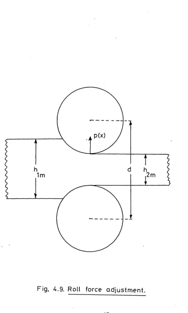
The roll force calculations are an important part of the static model. The amount of reduction in thickness of the strip is related to the total load in the mill or roll force. An extensive literature exists on the calculation of specific rolling force p(x) as a
function of input output thicknesses, input output tensions and work roll radius?5 i.e.,
P(x) = f(h1(x), h2 (x),01(x),CT2(x)> R). (3.11)
-When rolling hard materials, like stainless steel, very high forces must be applied. Since work rolls are elastic bodies they will be deformed and flattened at
46
the roll gap. In order to calculate the roll force, including the flattening effects, an iterative procedure must be adopted because the deformed roll . radius is a
/
function of the roll force. The deformed roll radius R
4347
can be calculated using Hitchcock’s formula ’ given as
! ' - ! + « £ & (3.12)
where c is a constant,
6 is the amount of reduction equal to Jh^(x) - h^x^, R is the initial roll radius.
The roll force may be calculated by solving eqs. (3.H) and (3.12) iteratively.
The disadvantage of the above approach for roll force calculation is the time the algorithm takes
to converge. For modelling purposes the width of the strip is split into 25 mm sections (this is to match the
physical dimensions of the back-up-roll) and the roll force must be calculated in each of these sections. Thus for one metre wide strip the roll force model must be made to converge forty times. The shape calculation is also iterative and thus all the roll force calculations must be performed on each of the iterations of the shape algorithm. Thus, although the roll force calculation does not require