GE-INTERNATIONAL JOURNAL OF ENGINEERING RESEARCH
VOLUME -3, ISSUE -5 (May 2015) IF-4.007 ISSN: (2321-1717)
A Monthly Double-Blind Peer Reviewed Refereed Open Access International e-Journal - Included in the International Serial Directories. GE- International Journal of Engineering Research (GE-IJER)
Website: www.aarf.asia. Email: [email protected] , [email protected]
Page 51
SMART CONTROL FOR VEHICLE HEADLIGHTS AND REAR-VIEW
MIRROR
Kriti Jain# , Aakrisht Mishra* , Abhishek Aggarwal* , Abhishek Sherawat* , Chetna Rajpal* , Iteshree Sharma*
#
Electronics and Communication Department, Amity University Haryana, India. * Electronics and Communication Engineering, Amity School of Engineering & Technology,
India.
ABSTRACT
Project SC-HR(Smart Control for Vehicle Headlights and Rear-View mirror) is
basically designed and optimized to give people a hand-over on accidents caused by High
Beam today (on Highways and in-city basically). SC-HR system works by automatically
detecting the high beam from the vehicle behind us and adjusts the rear-view mirror in such
position so that beam will not be a problem anymore for the driver. But as we speak of the
wrong usage of High-Beam in the city, sometimes we may ourselves commit the same
mistake. So to undermine our mistakes and reduce the manual work, SC-HR implements a
switching behavior between low and high beam on the headlights, based on the presence of
the vehicle in front of us (in the same or opposite lane). This project when applied in masses
can help a lot in the reduction of wrong High-Beam usage in city and side by side allows you
to use High-Beam on the highways without interrupting anyone’s sight or yourself getting
interrupted by others.
KEYWORDS- ATMEGA16A, HEADLIGHTS, L293D, LDR, REAR-VIEW MIRROR, SUNROM’S DOPPLER SENSOR
1. INTRODUCTION
According to ‘The Indian Express’, article [1] dated 10th Dec 2012 about 4.65% of cases
is registered in Bangalore City alone for wrong High-Beam usage. According to the Motor
Vehicle Act the high beams should be made dim if one can see a vehicle in front, at a distance
of 200 meters. The drivers having problems can also register their complaint against the
driver, by nothing but the vehicle number. The highest number of accident cases and deaths in
GE-INTERNATIONAL JOURNAL OF ENGINEERING RESEARCH
VOLUME -3, ISSUE -5 (May 2015) IF-4.007 ISSN: (2321-1717)
A Monthly Double-Blind Peer Reviewed Refereed Open Access International e-Journal - Included in the International Serial Directories. GE- International Journal of Engineering Research (GE-IJER)
Website: www.aarf.asia. Email: [email protected] , [email protected]
Page 52
399 cases, and Rs 11, 39, 900 was collected in fines. I mean why even 4.65%, why not reduce
it to null. Our project SC-HR is basically designed and optimized to give people a hand-over
on accidents caused by High Beam today (on Highways and in-city basically). We have used Sunrom’s Doppler Radar Sensors [4] for the vehicle detection in front and LDR [3] for detection of the following vehicle’s High Beam (behind us). A Stepper motor is used to help
rear view mirror adjust between its phases. An internal oscillator of 1 MHz is used as source
for our microcontroller’s internal timer. And a pushbutton is provided in case of requirement
of external hardware rest. SC-HR provides a smart control for Vehicle’s Head-Lights by
automatic detection of vehicle in front (in same and opposite lane) and for Vehicle’s Rear
View Mirror by automatic detection of High-Beam behind.
2. OVERVIEW OF THE COMPONENTS
2.1HIGH-BEAM DETECTION (BEHIND)
The High-Beam detection purpose for the SC-HR is handled by the LDR [3] photo
resistor. It is a light-controlled variable resistor. The resistance of a photo resistor decreases
with increasing incident light intensity.
As soon as the LDR [3] detects the dangerous level of light intensity it triggers the stepper
motor to rotate to the safe phase (safe phase for our rear-view mirror). To provide our Bipolar
Stepper Motor the required input we have used L293D [5] stepper interface IC.
Figure 1. LDR BASIC DIAGRAM
2.2VEHICLE DETECTION (FRONT)
Sunrom's Doppler Sensor [4] is used in the project as it helps in the detection of object
(vehicle) in front of our vehicle using Doppler Principle. The receiving of the signal is done by
a separate antenna to compare the received frequency with the reference frequency and
determine the change or shift in the frequency. This sensor has a transmitter and receiver,
transmitter generates a 10MHz wave which is captured when returns from the object and the
GE-INTERNATIONAL JOURNAL OF ENGINEERING RESEARCH
VOLUME -3, ISSUE -5 (May 2015) IF-4.007 ISSN: (2321-1717)
A Monthly Double-Blind Peer Reviewed Refereed Open Access International e-Journal - Included in the International Serial Directories. GE- International Journal of Engineering Research (GE-IJER)
Website: www.aarf.asia. Email: [email protected] , [email protected]
Page 53
states that if a source is moving with a relative velocity in respect to the transmitter, the wave
received will be having a shift in frequency or fluctuation. Astronomers use the color shift in
the light waves coming to us from astral bodies to identify the speed of source body and
whether they are travelling towards or away from the earth. In Doppler radar system, a known
frequency signal is transmitted from an antenna which is pointed at a reference object. The
basic formulas used for the calculation of the received frequency (fr) and other related
parameters is stated as:
[4]
Where, fr - is the received frequency
f0 - the frequency of transmitted wave
vs - relative speed of the source with radar
v0 - the speed of observer
v - the speed of the waves in the current medium.
For calculation of the shift in the frequency, the difference between the received and source
frequency is takes, as shown below:
[4]
Figure 2 is the block diagram [3] of sensor, a 10GHz oscillator is used for the generation of
the source wave and the Mixer used provide us with the output according to the difference in
frequency between transmitted and received (source frequency) frequencies. If there are no
moving objects received frequency will be of the same magnitude as that of the transmitted
wave and hence delivered output will be zero but if there is difference in frequency the output
GE-INTERNATIONAL JOURNAL OF ENGINEERING RESEARCH
VOLUME -3, ISSUE -5 (May 2015) IF-4.007 ISSN: (2321-1717)
A Monthly Double-Blind Peer Reviewed Refereed Open Access International e-Journal - Included in the International Serial Directories. GE- International Journal of Engineering Research (GE-IJER)
Website: www.aarf.asia. Email: [email protected] , [email protected]
[image:4.595.228.373.86.214.2]Page 54
Figure 2. BLOCK DIAGRAM OF SUNROM’S DOPPLER SENSOR (1195) [4]
If there are no objects in front of the Doppler sensor it’ll give a continuous analog output of
2.9V but as soon as an objects comes into play sensor will start showing fluctuation in its
output depending on the motion of the object with respect to our Doppler module.
According to the DC levels provided by the Doppler Sensor [4] the SC-HR intelligently
evaluates whether the vehicle needs to be in High-Beam mode or to switch to Low-Beam
mode.
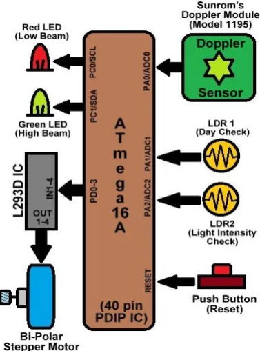
3. ARCHITECTURE AND METHODOLOGY
The architecture of the proposed physical system and methodology is given below. The
purpose of the system is:
a) To detect the day time and night time (In case of Day Time SC-HR stops all its
processes).
b) To detect a vehicle in front of us .
c) To detect whether the vehicle behind us is on low beam or high beam.
d) Arrive on a consensual decision and attenuate the head light and position of the rear
view mirror.
3.1DESIGN
In order for our system to operate efficiently, the system needs to be made as the
integral part of every vehicle. Depending on the output of our Doppler sensor fetched through
our ATmega16A’s ADC module, we decide whether to stay at the High Beam (In case it’s on
and is being used by the driver) or to switch it to low beam (In case an object comes in front
GE-INTERNATIONAL JOURNAL OF ENGINEERING RESEARCH
VOLUME -3, ISSUE -5 (May 2015) IF-4.007 ISSN: (2321-1717)
A Monthly Double-Blind Peer Reviewed Refereed Open Access International e-Journal - Included in the International Serial Directories. GE- International Journal of Engineering Research (GE-IJER)
Website: www.aarf.asia. Email: [email protected] , [email protected]
Page 55
whether its day or night and LDR2 is used to sense the light intensity coming from rear of the vehicle. Based on the LDR2 output again fetched through ATmega16A’s ADC we decide
whether to switch our rear-view mirror to SAFE or keep it at the DEFAULT position. For
rear-view mirror movement we are using a Bi-Polar stepper motor and an L293D IC from
interfacing our stepper with the ATmega16A. A reset button is introduced to reset our
microcontroller at the time of need.
[image:5.595.203.392.234.489.2]The system architecture is shown in the figure below:
Figure 3. BLOCK DIAGRAM OF SC-HR
3.2PROCEDURE
The presence of a vehicle is detected using Doppler sensor in our module. This
information is transferred to the ADC of the microcontroller, which is responsible for
processing the received inputs. The microcontroller then compares the processed
information with empirical threshold limits set. For the Doppler radar sensor 2.9v is the
continuous value given when no vehicle is present in front of it but if there is sudden
change in this continuous value, it means a vehicle is present in front of us. This value
ranges from 0-5v, which is also the working range of our microcontroller. So if the sensor
detects the vehicle the microcontroller initiates the communication with the modules in
GE-INTERNATIONAL JOURNAL OF ENGINEERING RESEARCH
VOLUME -3, ISSUE -5 (May 2015) IF-4.007 ISSN: (2321-1717)
A Monthly Double-Blind Peer Reviewed Refereed Open Access International e-Journal - Included in the International Serial Directories. GE- International Journal of Engineering Research (GE-IJER)
Website: www.aarf.asia. Email: [email protected] , [email protected]
Page 56
LDR photo resistors. One of the LDR photo resistor is used to sense the daytime and
night time based on the experimental values whereas the other one is used to detect
whether the vehicle behind us is on high beam or not. Both the LDRs are directly
interfaced with the microcontroller through PA1/ADC1 & PA2/ADC2 pins. Afterwards
the microcontroller decides whether to change the phase of the rearview mirror using a
bipolar stepper motor attached to it, which prevents the direct reflection of the light to
disturb the sight of the driver. The stepper motor is interfaced with the microcontroller
through an IC L293D.
4. SC-HR INTERFACING
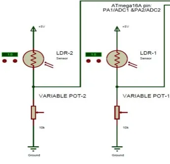
4.1LDR AND BIPOLAR STEPPER MOTOR
A Light Dependent Resistor (LDR) or a photo resistor is a device whose resistivity is
a function of the incident electromagnetic radiation. Hence, they are light sensitive devices.
They are also called as photo conductors, photo conductive cells or simply photocells. They
are made up of semiconductor materials having high resistance. We are using two LDRs, one
for the detection of high beam behind us (LDR1) & other for the determination of day or
night (LDR2). Both the LDRs are directly interfaced to ATmega16A through PA1/ADC1 &
PA2/ADC2 pins, which have an internal Analog-to-Digital converter. This analog output is
[image:6.595.209.382.498.664.2]then converted to 10-bit digital data according to which our stepper motor is acted upon.
GE-INTERNATIONAL JOURNAL OF ENGINEERING RESEARCH
VOLUME -3, ISSUE -5 (May 2015) IF-4.007 ISSN: (2321-1717)
A Monthly Double-Blind Peer Reviewed Refereed Open Access International e-Journal - Included in the International Serial Directories. GE- International Journal of Engineering Research (GE-IJER)
Website: www.aarf.asia. Email: [email protected] , [email protected]
Page 57
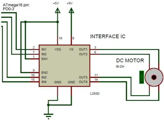
To interface Bipolar-Stepper Motor with ATmega16A we have used L293D IC, which is
connected to ATmega16A through PD0-PD3 pins. And stepper motor is connected to L293D
[image:7.595.161.432.151.349.2]through its OUT1-OUT4 pins.
Figure 5. BIPOLAR STEPPER MOTOR INTERFACING WITH ATMEGA16A
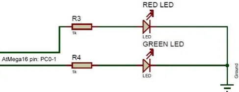
4.2DOPPLER SENSOR AND LED INTERFACING
Sunrom’s Doppler Sensor (Model No. 1195) [4] have 3 pins out of which first and
third are used as Vcc and Ground respectively. Third pin is A.Out (Analog Output) which is
interfaced to AtMega16 [2] through PA1/ADC1 pin, which have an internal
Analog-to-Digital converter. This analog output is then converted to 10-bit digital data according to
which our SC-HR decides whether to be on High-Beam (Red LED) or Low-Beam (Green
LED). Our Red LED and Green LED is interfaced with AtMega16 [2] through PC0 and PC1
GE-INTERNATIONAL JOURNAL OF ENGINEERING RESEARCH
VOLUME -3, ISSUE -5 (May 2015) IF-4.007 ISSN: (2321-1717)
A Monthly Double-Blind Peer Reviewed Refereed Open Access International e-Journal - Included in the International Serial Directories. GE- International Journal of Engineering Research (GE-IJER)
Website: www.aarf.asia. Email: [email protected] , [email protected]
[image:8.595.163.425.95.259.2]Page 58
Figure 6. DOPPLER SENSOR INTERFACING WITH ATMEGA16A
Figure 7. RED & GREEN LED INTERFACING WITH ATMEGA16A
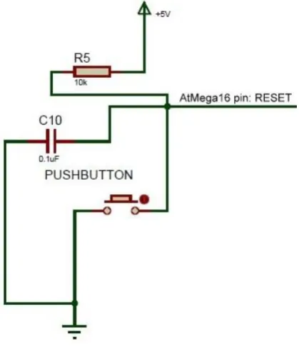
4.3Push Button Interfacing (RESET)
Push-Button is introduced in the circuit to hard reset our micro-controller when
[image:8.595.172.416.340.434.2]GE-INTERNATIONAL JOURNAL OF ENGINEERING RESEARCH
VOLUME -3, ISSUE -5 (May 2015) IF-4.007 ISSN: (2321-1717)
A Monthly Double-Blind Peer Reviewed Refereed Open Access International e-Journal - Included in the International Serial Directories. GE- International Journal of Engineering Research (GE-IJER)
Website: www.aarf.asia. Email: [email protected] , [email protected]
[image:9.595.199.409.92.337.2]Page 59
Figure 8. PUSH BUTTON INTERFACING WITH ATMEGA16A
5.BASIC FLOW DIAGRAM
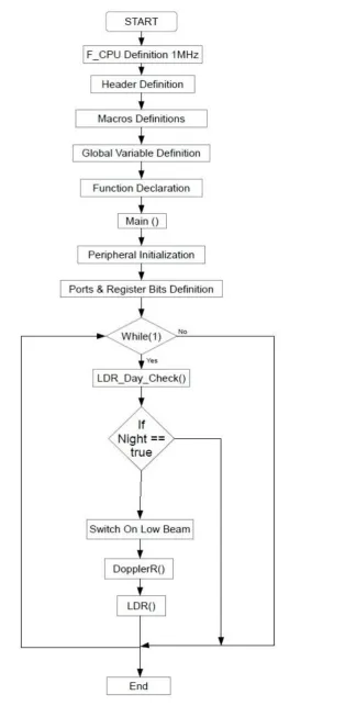
5.1MAIN FUNCTION
In our main function of the firmware we have done all necessary kinds of definitions,
declarations and initializations for the execution of our firmware. On the base line, we are
calling our LDR and DopplerR functions repeatedly for infinite times using while(1) loop
only when our function LDR_Day_Check allows us to do so. F_CPU definition is used by the
delay_ms() function of <util/delay.h> for giving appropriate user defined delays in between
program. Macros are used for easy manipulation of the experimental values. Peripherals and
GE-INTERNATIONAL JOURNAL OF ENGINEERING RESEARCH
VOLUME -3, ISSUE -5 (May 2015) IF-4.007 ISSN: (2321-1717)
A Monthly Double-Blind Peer Reviewed Refereed Open Access International e-Journal - Included in the International Serial Directories. GE- International Journal of Engineering Research (GE-IJER)
Website: www.aarf.asia. Email: [email protected] , [email protected]
[image:10.595.162.477.78.722.2]Page 60
GE-INTERNATIONAL JOURNAL OF ENGINEERING RESEARCH
VOLUME -3, ISSUE -5 (May 2015) IF-4.007 ISSN: (2321-1717)
A Monthly Double-Blind Peer Reviewed Refereed Open Access International e-Journal - Included in the International Serial Directories. GE- International Journal of Engineering Research (GE-IJER)
Website: www.aarf.asia. Email: [email protected] , [email protected]
Page 61
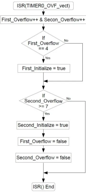
5.2ISR (INTERRUPT SERVICE ROUTINE)
Interrupt Service Routine in short called as ISR is the segment of the firmware to
which our compiler goes when it experiences an interrupt, the interrupts can be software or
hardware interrupts. Here each time program comes to ISR (in our case it comes after 250 ms
each time Timer1 counter overflows) we increment two variables, First_Overflow &
Second_Overflow, and as soon as that variable satisfies our condition respective Initialize
variables are getting a true value. These Initialize variables will help us in a controlled and
[image:11.595.205.386.278.681.2]timed execution of our LDR and DopplerR functions.
GE-INTERNATIONAL JOURNAL OF ENGINEERING RESEARCH
VOLUME -3, ISSUE -5 (May 2015) IF-4.007 ISSN: (2321-1717)
A Monthly Double-Blind Peer Reviewed Refereed Open Access International e-Journal - Included in the International Serial Directories. GE- International Journal of Engineering Research (GE-IJER)
Website: www.aarf.asia. Email: [email protected] , [email protected]
Page 62
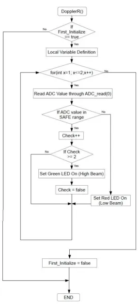
5.3DOPPLERR FUNCTION
In our project we have used DopplerR function to basically fetch and process the digitally converted output (through internal AtMega16 ADC) of the Sunrom’s Doppler
Sensor [4] and set our headlights to an appropriate mode based on the presence of the vehicles in front of us. We’re using a variable ‘check’ to help us in checking the output value
twice before switching our headlights to the High-Beam mode. This dual check is required so
as avoid switching of our headlights on the basics of so called ‘by-chance values’. As our
Doppler sensor shows fluctuating voltage when there is an object motion in front, hence there
GE-INTERNATIONAL JOURNAL OF ENGINEERING RESEARCH
VOLUME -3, ISSUE -5 (May 2015) IF-4.007 ISSN: (2321-1717)
A Monthly Double-Blind Peer Reviewed Refereed Open Access International e-Journal - Included in the International Serial Directories. GE- International Journal of Engineering Research (GE-IJER)
Website: www.aarf.asia. Email: [email protected] , [email protected]
[image:13.595.153.441.76.705.2]Page 63
GE-INTERNATIONAL JOURNAL OF ENGINEERING RESEARCH
VOLUME -3, ISSUE -5 (May 2015) IF-4.007 ISSN: (2321-1717)
A Monthly Double-Blind Peer Reviewed Refereed Open Access International e-Journal - Included in the International Serial Directories. GE- International Journal of Engineering Research (GE-IJER)
Website: www.aarf.asia. Email: [email protected] , [email protected]
Page 64
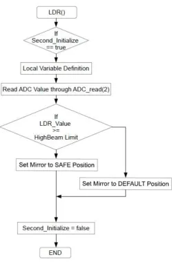
5.4LDR FUNCTION
LDR function is defined to fetch the ADC value from micro-controller’s ADC2 pin
and based on the value decides whether to switch rear-view mirror to DEFAULT and SAFE
[image:14.595.175.425.183.563.2]position.
Figure 12. FIRMWARE’S LDR FUNCTION
5.5LDR_DAY_CHECK FUNCTION
LDR_Day_Check function helps SC-HR in distinguishing between day and night. Based on this function’s output SC-HR decides whether to run LDR and DopplerR function
GE-INTERNATIONAL JOURNAL OF ENGINEERING RESEARCH
VOLUME -3, ISSUE -5 (May 2015) IF-4.007 ISSN: (2321-1717)
A Monthly Double-Blind Peer Reviewed Refereed Open Access International e-Journal - Included in the International Serial Directories. GE- International Journal of Engineering Research (GE-IJER)
Website: www.aarf.asia. Email: [email protected] , [email protected]
[image:15.595.206.434.88.349.2]Page 65
Figure 13. FIRMWARE’S LDR_DAY_CHECK FUNCTION
6. CONCLUSIONS
SC-HR senses the High-Beam intensity through LDR [3] coming from the vehicle behind us
and gives us a dc output which then converted to 10-bit digital data through ADC. If the light
intensity is over the danger level the stepper motor switches the rear-view mirror to the safe
position and soon as the light intensity drops the rear-view mirror will come back to its default position. We used Sunrom’s Doppler Sensor (Model No. 1195) [4] which help us in
the detection of any vehicle in front of us and helps us switching our headlights from
High-Beam mode to Low-beam mode in the case any vehicle is present. This headlight switching
behavior helps us in utilizing the High-Beam for our purpose while not disturbing any other
drivers moving in front of us. This overall system (SC-HR) is designed for being integrated
with any vehicle irrespective of their model or type, and in mass application will solve a lot
of problem for citizen and our Traffic Police department.
REFERENCES
[1] The Indian Express Article,
GE-INTERNATIONAL JOURNAL OF ENGINEERING RESEARCH
VOLUME -3, ISSUE -5 (May 2015) IF-4.007 ISSN: (2321-1717)
A Monthly Double-Blind Peer Reviewed Refereed Open Access International e-Journal - Included in the International Serial Directories. GE- International Journal of Engineering Research (GE-IJER)
Website: www.aarf.asia. Email: [email protected] , [email protected]
Page 66
[2] AtMega16A Datasheet, Link: http://www.atmel.com/devices/atmega16a.aspx
[3] LDR, Link: http://www.resistorguide.com/photoresistor/
[4] Sunrom’s Doppler Sensor Datasheet, Link:
http://www.sunrom.com/p/microwave-doppler-radar-sensor-for-motion-and-speed-sensing
[5] L293D IC, Link: http://www.ti.com/product/l293D
[6] About High-Beam and its adverse effect on driving, Link:
https://safedriving.wordpress.com/2013/10/05/the-best-way-to-use-high-beam-headlights/
[7] HIGH Beam Assist, Link:
http://www.audizine.com/forum/showthread.php/487621-HIGH- Beam-ASSIST
[8] High Beam Control, Link:
https://www.mazda.ie/videos/technology/high-beam-control-making- driving-safer-and-more-convenient/
[9] Electronic Devices and Circuit Theory by Boylestad, Pearson Education India, Link:
http://books.google.co.in/books/about/Electronic_Devices_and_Circuit_Theory.html?id=32R
JvfgkJgwC
[10] Analog and Digital Circuits for Electronic Control System Applications by Gerald
Lueck, Link:
https://books.google.co.in/books?id=lKy56FZkNzsC&printsec=frontcover&dq=Digital+Circ
uits+and+System&hl=en&sa=X&ei=xglFVdzxKImTuAS7jYG4CQ&redir_esc=y#v=onepag
e&q=Digital%20Circuits%20and%20System&f=false
[11] Rear-View Mirror, Link: http://en.wikipedia.org/wiki/Rear-view_mirror
![Figure 2. BLOCK DIAGRAM OF SUNROM’S DOPPLER SENSOR (1195) [4]](https://thumb-us.123doks.com/thumbv2/123dok_us/48133.1008208/4.595.228.373.86.214/figure-block-diagram-sunrom-s-doppler-sensor.webp)