Marino, MD (2018) RAMON: Region Aware Memory Controller.
IEEE Transactions on Very
Large Scale Integration (VLSI) Systems, 26 (4).
pp.
697-710.
ISSN 1063-8210 DOI:
https://doi.org/10.1109/TVLSI.2018.2789520
Link to Leeds Beckett Repository record:
http://eprints.leedsbeckett.ac.uk/4683/
Document Version:
Article
The aim of the Leeds Beckett Repository is to provide open access to our research, as required by
funder policies and permitted by publishers and copyright law.
The Leeds Beckett repository holds a wide range of publications, each of which has been
checked for copyright and the relevant embargo period has been applied by the Research Services
team.
We operate on a standard take-down policy.
If you are the author or publisher of an output
and you would like it removed from the repository, please
contact us
and we will investigate on a
case-by-case basis.
RAM ON
:
R
egion
A
ware
M
emory C
on
troller
Mario D. Marino, Kuan-Ching Li
Leeds Beckett University, Providence University
[email protected], [email protected]
Abstract—
Recent implementations of heterogeneous multicore systems (CPU, GPU and hybrid) address the issue of communication latency between CPU and GPU memory systems by merging these two, so that they can share the same memory address space. In recent years, the combination of the escalation in the number of cores with the rise in memory-intensive applications has significantly increased bandwidth needs in both homogeneous and heterogeneous systems. Since tasks assigned to CPU and/or GPU cores will have different bandwidth demands, a two-tier memory system is needed. Hence in this paper,RAM ONis proposed as a configurable memory system where different address space regions are able to be dedicated to a different number of memory controllers (MCs), concurrently to supply different amounts of bandwidth to a different number of cores, providing different levels of memory parallelism. By having different address space regions - simply regions, each with a different number of MCs to match its bandwidth needs, memory interference per region is reduced. Our findings show that RAM ON
is promising and improves bandwidth by a factor of 9x for CPU regions, 14.1x for GPU regions, and 4.5x for combined heterogeneous regions.
I. INTRODUCTION
Recent multicore chip implementations are composed of
heterogeneous (central processing unit,i.e.CPU, and graphics
processing unit,i.e. GPU) cores. The need for more cores to
improve performance combined to memory-bound programs execution significantly intensifies memory contention. For ex-ample, high-end smartphones [1] and desktops [2] have 16 cores, which are likely to be further pushed to 32 or more cores given demands for Big-Data, image processing and interactivity.
Before integration of heterogeneous cores in one single multicore chip, typical communication between CPU and GPU cores was often performed via a Peripheral Component Interconnect Express (PCIe) bus [3]. Despite width and clock frequency augments in this bus, as well as improvements in effective communication coordination by the application
(e.g., buffering and overlapping in software pipelining [4]),
bandwidth between CPUs and GPUs is still dictated by the speed of this bus.
In order to overcome this communication bottleneck, CPU and GPU cores are set to share the same address space to form a heterogeneous region (further detailed) on the same multicore chip, thus allowing data exchange through exchanging addresses, rather than transferring contents via PCIe. As a result, communication latencies are significantly reduced, which allows performance improvements. However, this approach requires both types of cores to share one single address space, which further pushes the demands on the memory system side.
As reported in [5] [6] [7] [8] [9], despite differences
among cores and bandwidth-bound applications trends, another layer of contention that reduces the performance is represented by memory interference due to different programs running on different cores with different demands on the memory channels.
A straightforward solution to address bandwidth needs in future multicore generations is via the augment of memory parallelism by increasing the number of memory controllers (MCs), which are assumed to be connected to its ranks (typically known as dual inlined memory module - DIMM, that are sets of memory banks with data output aggregated and sharing addresses). To exemplify sets of multiple MCs/ranks, typical PCs present 2MCs/2ranks, embedded Tilera [10] mi-croprocessor with 4MCs/4ranks, and IBM-Cisco router [11], 16MCs/16ranks. However, according to Marino [12] the in-crease on the number of MCs is restricted by the number of I/O pins. To address these I/O pin issues, the number of I/O pin-based structures should be increased, while still respecting the low power aspect.
Solutions that use a larger number of MCs typically rely on the principles of modulation and different media [13][14]. Multiple frequency carriers can carry multiple data simulta-neously over the same media, which can dramatically save pin utilization whilst remaining significantly power-conscious [13][14]. With reduced pin utilization, the number of MCs can be increased to significantly higher levels. For example, in either optical Corona [14] or in radio-frequency (RF) DIMM Tree [13], no more than 64 MCs can be utilized.
To illustrate the benefits of a larger number of MCs, using 32 RF-based MCs Marino [12] indicates a bandwidth improvement factor of about 7.2x compared to 2-4 MCs in typical microprocessors. Furthermore, according to Vantrease et al. [14], an optical interface allows memory energy inter-connection to be significantly reduced, which is fundamentally important when exploring different numbers of MCs.
In this investigation, different degrees of memory paral-lelism are proposed to be achieved through different number
of MCs with optical- [14] or RF-based [12] memory
interfaces applied to different types of regions (CPU, GPU
or heterogeneous), that is,RegionAwareMemory Controller
(RAM ON). Under several bandwidth-bound benchmarks
us-ing detailed-accurate simulators, RAM ON presents the
fol-lowing contributions:
• Revisiting the operating system (OS) concept of address
space used by Marino and Li’s report [15], inRAM ON
the novel concept of region is defined as an address space range dedicated to different sets of cores (CPU, GPU, or both), caches and respective interconnection. The inclusion of the two latter elements differentiate
RAM ONfrom Non Uniform Memory Access (NUMA-node) mechanism in Linux OS. MC region awareness in
• In RAM ON a novel scheme of reorganization and property isolation is proposed to reduce or eliminate memory interference and defined as follows. The reor-ganization operation of a region permits the change on
the number of MCs associated to it i.e., and different
degrees of memory parallelism, thus likely reducing memory contention via reducing memory interference. Through reorganization, traffic of regions are ”more” self contained - isolation property - which can reduce or eliminate memory interference (i.e. related memory requests) that do not belong to the region, as further discussed. This novel scheme is enabled via the proposal of a low-overhead configurable optical-crossbar.
• Architectural investigation of RAM ON system
impli-cations when increasing the number of MCs for CPU, GPU, and heterogeneous regions. This investigation aims to determine the performance and power behavior of several degrees of memory parallelism - represented by different numbers of MCs. To develop this RAMON investigation we vary the number of MCs for the dif-ferent types of regions exploring significant larger MC number of optical- and RF-based interfaces.
• An evaluation on system implications of larger number
of MCs applied to different types of regions rather than to the same type of regions performed in [12] [16].
• An evaluation on system implications for larger numbers
of MCs in heterogeneous regions via using optical-and RF-based interfaces (signal modulation) rather than traditional digital transmission (where, to transmit a ”0” or a ”1”, the whole line should be entirely set to the respective level) developed in [15].
• The methodology utilized to determine the performance
when CPUs and GPUs are combined is an improved
version over the proposed in [15]. The methodology
consists of running each simulator (CPU and GPU) independently in regions that contain the maximum number of MCs allocated to each one. A formulation to estimate the bandwidth of heterogeneous systems is developed and compared to homogeneous ones.
• A user-feedback scheduling algorithm is introduced
aiming to reorganize regions in order to match the bandwidth needs of that region. Consecutive runs of this algorithm and reconfigurations can likely guide the user to determine proper allocation of tasks as further described.
• The increase in the number of MCs using optical or RF
interconnections has been investigated in current OOO microprocessors [12][17][16]. In order to investigate the impact of the number of MCs on heterogeneous regions, we have to investigate it on CPU-regions - which we compare to previous research [12] - as well as on GPU-regions.
It is assumed that coherency aspects and scheduling of regions of the memory system are beyond the scope of this investiga-tion, assuming that coherency and scheduling of programs are treated at the programming level environment. The remainder of this paper is organized as follows. Section II describes the background and motivation for increasing the MCs towards
improving bandwidth, and Section III describes RAM ON’s
properties of creation, isolation, and reorganization of regions.
...
L1 CPU
L2
L1 CPU
L2 L1 CPU
...
memory memory memory L3
L1 L1
L1
L2 L2
L2
processing processing processing
unit
unit
unit
memory memory memory
MC MC
memory channel memory channel
memory channel
MC L2
memory channel memory channel memory channel
GPU region CPU region
MC MC
crossbar
MC
scheduled
request 16 MCs
example 2 example 1
request 1 MC
example 3
request 16 MCs
scheduling
application
scheduled
scheduled
16 sequential tasks
1 sequential task
1 heterogeneous task
example 1
request 16 MCs 1 heavily parallel task
example 2
request 31 MCs 1 heavily parallel task
example 3 1 heterogeneous task
request 16 MCs scheduled
scheduled
[image:3.612.317.567.51.356.2]scheduled
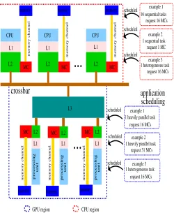
Fig. 1: CPU region and GPU region executing tasks
In Section IV, experimental methodology and results are
discussed. Section V analyzes the sensitivity of RAM ON
operations and methodology. Section VI describes the related work whilst Section VII the conclusion remarks and future directions.
II. BACKGROUND ANDMOTIVATION
Marino [12] characterizes the I/O pin problem as a set
of physical restrictions likely to occur when the number of I/O pins increases, larger pin-densities are employed, and faster clocks (666 MHz to 1.3 GHz or more) along the processor-to-memory channel are implemented. These I/O pin restrictions involve electro-migration, crosstalk effects among pins [16], as well as a reliable design connection between the motherboard and the processor chip [12]. In addition, as the number of I/O pins is increased, area costs are likely to increase correspondingly.
Therefore, (a) and (b) demonstrate the need to focus on systems with a larger number of MCs to tackle the approach targeting a larger number of cores, so that techniques that provide the utilization of a larger number of MCs are described next.
Optical and RF technologies enable the exploration of large bandwidth whilst using a small number of special pins, which are designed for these technologies. Modulation in these technologies enables the multiplexing of simultaneous carriers which transmit simultaneous data, thus allowing significantly larger bandwidth when compared to traditional transmission with no modulation. To illustrate how modulation benefits bandwidth in optical- or RF-modulation, bandwidth-per-pin is defined similarly to [15]:
bw pin=ncarrier∗data rate/number of IO pins (1)
This equation shows that by reducing the number of pins bandwidth-per-pin can be improved. Considering waves rep-resented by multiple carriers placed at different frequency ranges, as carriers are added larger data rates are achieved. By using a low amount of pins, all of those combined can generate higher bandwidth-per-pin magnitudes.
The following examples further illustrate the importance of reducing pin utilization in MCs. For example, optical Corona [14] only presents 2 optical pins/MC, whilst RFiof [12] about 4 RFpins, therefore pin magnitude is noticeably reduced when compared to 120 pins (of 240 pins total) utilized in traditional DDR systems, thus enabling the use of a larger number of MCs.
To estimate bandwidth improvements when augmenting the number of MCs, we utilize the equation developed in [15]:
BwP =rank f requency ∗ width ∗ M Cs (2)
where BwP represents the peak bandwidth the memory
sys-tem can supply, rank f requency represents the rank clock
frequency or data rate, and width refers to the number of
bits which represent the width of the rank. Equation 2 simply allows to derive that peak bandwidth increases as the number of MCs is increased, which means a larger degree of memory parallelism.
Considering all elements on the memory path between
the core and the rank, peak bandwidth degrades due to
cache delays, crossbar contention, interconnection delays, MC delays, memory bank delays, and program instructions which effectively use memory (read and write). As all effects are independent, effective bandwidth is obtained as follows:
Bw=BwP ∗ (1 − M isslatency%)
∗ (1 − BusDelay%)∗ (1 − M Cdelay%)
∗ (1 − N etworkCacheAndContention%)
∗ (1 − interconnectionDelay%)
∗ (1 − ActiveState%)∗ (1 − N oReadW rite%)
(3)
where Bw is the effective bandwidth supplied to the cores
(either CPU, GPU, or both), M isslatency% corresponds to
the fraction of time spent on cache miss delays,BusDelay%
the fraction of time spent on bus delays, M Cdelay%
the fraction of time spent at the MC queue/processing,
N etworkCacheAndContention%the fraction of time spent
on cache occupation,interconnectionDelay%the fraction of
time spent at optical- or RF-interconnection, ActiveState%
the fraction of time memory banks are active (read and write
operations occur), and N oReadW rite% the fraction of time
read and write operations are not present. Effective bandwidth
(Bw) follows peak bandwidth (BwP), and is still proportional
to the increase on the number of MCs.
Through a careful design that includes control of impedance matching and interference, signal degradation, dispersion, and divergence effects during transmission [15] are minimized. Consequently, energy interconnection is minimized. For
in-stance, Vantrease et al. [14] illustrated an interconnection
energy reduction of about 80% when compared to traditional transmission. Additionally, lower area utilization [16] favors the utilization of a larger number of MCs based on either technologies.
III. RAM ON MANAGEMENT OFREGIONS InRAM ON we assume that each region keeps all commu-nication needed mostly self-contained in the region, avoiding CPUs/GPUs of different regions to access one or multiple re-gions. Traffic is not self-contained when different regions need the OS. As further described, a proper OS allocation to a region can potentially allow lesser OS inter-region communication. Despite being beyond this study, complete isolation could be achieved by having multiple copies of the OS in all regions at the expense of extra overhead to run these multiple OS copies, which would also require a master OS to keep control of the other OS copies.
A. User/OS Scheduling Assumptions in RAM ON
RAM ON allows the creation of new regions and/or the reorganization of previous existing ones in terms of the number of MCs. Heterogeneous tasks are considered to be a combi-nation of CPU- and GPU-tasks, and assumed to be scheduled and executed on heterogeneous regions. Furthermore, hetero-geneous tasks are assumed to be created, scheduled, controlled and triggered by the user (e.g. OpenCL [19]) or OS according to bandwidth selection or Quality of Service (QoS) [9] level of the aimed bandwidth.
These tasks are assumed to invoke RAM ON operations
and region management. In this scenario, the frequency of the creation and reorganization operations is controlled and triggered by the user/OS. Additionally, the user/OS are as-sumed to be responsible for controlling synchronization via invoking the creation operation of separated regions so that memory interference is minimized. Since there are overheads to perform region operations, these overheads are of lower time when compared to software ones (e.g. synchronization among threads and memory allocation). Further considerations are discussed along this section.
Though beyond this study, the following user-based feed-back bandwidth-scheduling mechanism is proposed to be ap-plied to a set of tasks in order to explore different degrees of memory parallelism offered by different number of MCs:
1) For each individual task running in one region, identify
queues. These counters could be exposed to the user as performance counters. Repeat this step for each task of the set.
2) A new reference degree of memory parallelism for an
individual task can be estimated by the user/OS via as-signing different number of MCs to each created region or reorganized region. As a result, the configurations with the highest performance can be found. Region aspects are discussed in the following subsections.
3) Given the most bandwidth-performing region
configu-rations references were found in the previous step, the user/OS can select the number of MCs to perform the target region reconfiguration to achieve the bandwidth goals whilst scheduling tasks via assigning or com-bining them to be run into separate or shared regions aiming to achieve the required bandwidth.
The proposed mechanism can be integrated to other reported mechanisms such as [5] [6] [7] [8] [9] [21] further described in Section VI. The proposed mechanism assumes applications with constant bandwidth demand behavior. However, by split-ting the tasks execution into time phases in which bandwidth is approximately constant as well as estimating bandwidth and reconfiguring the regions based into on the mentioned time phases as previously indicated, the algorithm can be repurposed to target variable bandwidth.
In all previous assumptions, RAM ON exposes to the
user/OS the capability of creating new regions and/or recon-figuring these regions in terms of number of MCs. Further-more and importantly, given these previous considerations, with a careful user/OS software-level application scheduling and proper configuration of the MCs in different regions, interference-related traffic among regions and likely delays are likely to be reduced as further discussed.
B. Creation of CPU, GPU, and Heterogeneous Regions As previously mentioned, each region is defined as a range of addresses and a set of MCs associated with it. Each region is likely to have a task or multiple tasks being executed using the same address space and a dedicated number of MCs. Since the number of cores/caches/MCs in each region is reconfigurable, interleaving address mapping needs to be changed accordingly. Once MCs are subject to the modification of the address mappings on the caches, a region reconfiguration should consider a new interleaving of address mappings, which should be explored by the tasks allocated to that region.
Assuming that cache requests are interleaved at MCs, each region accesses a range of addresses according to the available number of MCs. Therefore, addresses accessed within one region are guaranteed to be different, which means that the regions are isolated. The only exception is to access OS-related data/programs out of the region, if the OS is not allocated to that region.
We illustrate the creation of different regions in Figure 1 based on [15] - different regions with homogeneous and heterogeneous behaviours.
The crossbar utilizes region boundaries in order to de-limit traffic inside each of these regions. Each region has a unique identifier at the crossbar (further described in Subsec-tion III-E1). When the creaSubsec-tion operaSubsec-tion is performed, a new region is formed with the proper number of MCs and respective
tasks associated. In the case creation operation is successful, likely-configurations with the appropriate MC counts dedicated to the tasks are created. The creation operation (designed to happen at creation time) fails when the configuration requested or the number of MCs associated are not available to meet the request and the user/OS is informed to reduce the number of MCs requested.
As mentioned before, when multiple tasks are successfully initialized at the crossbar regions are created accordingly. For instance, at the initial phase presented in Figure 1, the application requests the creation of two different regions. Next, the application is able to schedule tasks to two different regions (CPU and GPU).
C. Isolation of Regions
Tasks associated to a region mostly access memory ad-dresses within that region, thus guaranteeing that most memory traffic is contained within it. Isolation means that the MCs assigned to each created region allow tasks to proceed with their memory accesses, regardless of other tasks executed in other regions. Also, tasks executed in different regions use different numbers of MCs - each region likely to have a different level of memory parallelism. Therefore, by having traffic mostly self contained, memory interference of one region in respect to another region is mostly reduced (with the previous assumptions that only OS accesses are allowed to cross regions). Additionally, if a region is set to run more than one task and these tasks share multiple MCs, these tasks are likely to cause memory interference. Instead, if two regions are created, each one with separate MCs, a lesser amount of traffic interference is likely to happen within each region.
D. Bandwidth Behavior
We assume cache addresses are interleaved on each MC and that each region has a set of MCs dedicated to it. Memory traffic between cores and MCs are mostly kept inside each
region, i.e., memory traffic between cores and MCs that do
not belong to that region is avoided. Some likely scenarios to be observed are the following:
1) If MCs of a certain region were shared with another
one, these MCs would receive more traffic, thus likely to cause a latency increase. However, if each region has its own set of MCs, the set of each region would receive its corresponding memory traffic predominantly. Therefore, memory interference of other regions is significantly reduced.
2) When executing bandwidth-bound programs, memory
traffic generated to respond to processor requests goes through the cache network to get back to the cores. Therefore, regions with larger cache network traffic are likely to be subject to larger congestion. Consequently, if properly separated at the crossbar, these regions can have traffic minimized from the others, and network interference is also reduced.
LetM Csbe the total number of MCs available. Assuming
l1cache 0
resonator ring
registers config
core 0 +
...
core i +...
resonator ring
registers
config resonatorring
core n +
l1cache n l2cache n
l2cache 0 l1cache i core 1 +
l1cache 1
config registers
l2cache i
ring
conf conf conf conf resonator
registers config
config = configure conf = configuration
l2cache 1
optical crossbar
address
address address
optical waveguides
address registers
resonator ring
conf
conf = configuration
control signal coupling region
coupling region
control signal
add port
waveguide waveguide
drop port input port throughout port
[image:6.612.57.552.52.270.2]config
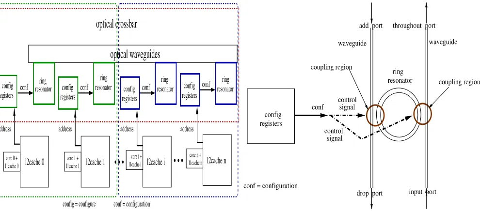
Fig. 2: left to right: Fig 2a crossbar design and Fig 2b configuration signal/ring resonator
We start by considering that the memory system has the same properties, regardless of the type of region. As previously
mentioned in Subsection II, effective memory bandwidth (Bw)
supplied to any of the regions (CPU, GPU, or heterogeneous) follows the number of MCs:
Bw= rank f requency ∗ width ∗ M Cs
∗ (1 − M isslatency%)∗ (1 − BusDelay%) ∗ (1 − N etworkCacheAndContention%)
∗ (1 − M Cdelay%)∗ (1 − RF interconnectionDelay%)
∗ (1 − ActiveState%)∗ (1 − N oReadW rite%) (4) If available MCs are assigned to a region, through isolation these are mostly used for dealing with memory requests generated by the cores on that region. For example, assuming we have two heterogeneous regions, one with 75% of the MCs available and the other one with the rest (25%), thus from equation 5, the first heterogeneous region (A) would have:
BwhetA = rank f requency ∗ width ∗ 0.75 ∗ M Cs
∗ (1 − M isslatency%)∗ (1 − BusDelay%) ∗ (1 − N etworkCacheAndContention%)
∗ (1 − M Cdelay%)∗ (1 − RF interconnectionDelay%) ∗ (1 − ActiveState%)∗ (1 − N oReadW rite%)
(5)
where BwhetA is the effective bandwidth supplied to
het-erogeneous region A. Similar equation can be developed for heterogeneous region B (replacing 0.75 with 0.25) and with
both we can state thatBwhetA > BwhetB, which proves
(1). Analogously, case (2) can be demonstrated using the same equations. More specifically, memory-bound applications enable the generation of cache requests at the CPU-, GPU-, or heterogeneous-regions. The respective memory responses to these cache requests are generated at the ranks - memory traffic - and repassed to the MCs, which themselves repass to the crossbar/cache network. In this case, the network traffic
of a heterogeneous region would contain memory requests generated at CPU and GPU cores and is comparatively larger - likely to cause larger interference on the MC channels - than the respective CPU and GPU regions.
E. Reorganization of Regions
Similarly to the creation, new identifiers are assigned so that the region can be manipulated at the crossbar as further described. At any point, reorganization of regions redefines any existing address spaces as well as the number of MCs allocated to it. Similarly to region creation, the amount of bandwidth needed and respective MCs that enable that region to achieve user desired bandwidth, whilst the creation of separated regions associated to different tasks can decrease memory traffic per MC - which reduces memory interference.
Importantly, if a region is reorganized, that means this region is going to be decoupled in different regions. Since reorganization of a region is assumed to be controlled by the user/OS, the latter are in charge of reorganizing the regions and assumed to associate new or previous tasks to these new regions. To implement reorganization, we propose a reconfigurable crossbar described next.
1) Crossbar Description and Design Scheme: The crossbar is a key element not only in the reorganization operation in
RAM ON but also on the other operations as well (creation and isolation).
To understand the crossbar design and how address region isolation is implemented, we first show how MCs are grouped and dedicated to a region. Unique identifiers are associated to each MC with the assumption of cache addresses interleaved at each one of them. Since the address space and proper amount of MCs can be used by tasks associated to that region, memory traffic destined to a certain MC can be
identi-fied by comparingaddress mod(M CsDedicatedT oRegion)
(address represents a general address, mod represents the
modulo operation, M CsDedicatedT oRegion represents the
Importantly, when executing tasks, region boundaries are used to prevent addresses from going out of bounds of that region, thus guaranteeing that cache addresses are spread at the sets of MCs associated to that region.
By guaranteeing memory traffic is kept within the bound-aries corresponding to the set of MCs dedicated to that region, memory traffic out of the region is avoided, which reduces memory traffic destined to other MCs that belong to other regions, i.e., it reduces the interference of other regions. Fur-thermore, by having consecutive MC identifiers dedicated to a region, network traffic of that region can be isolated. Region boundaries are utilized at the crossbar to set the reconfiguration hardware, formed by sets of registers and comparators, as follows:
• Registers are required to perform creation and
config-uration operations. These registers contain the address boundaries of each created or reorganized region, and are assumed to be exposed to the user/OS scheduling described in Subsection III-A.
• address mod(M CsDedicatedT oRegion)calculations are implemented in circuits via shift registers and XOR elements. Since these calculations can occur frequently so that memory traffic is isolated inside each region, the hardware elements needed can be implemented in separate at the microprocessor decode hardware unit, thus not incurring additional overhead.
• Comparators are also required to enforce memory and
network traffic isolation. These comparators check the validity of the address with respect to the boundaries of that region, ensuring that the memory traffic is mostly self-contained to that region. Each region has its own comparators that guarantee that traffic is contained in each of them.
• We assume that the memory interfaces are based on
optical and RF technologies. Therefore, the crossbar is likely to be designed according to the modulation, transmission, and proper pin-based interfaces required by these technologies.
• Registers’ and comparators’ circuits complexity grows
linearly with the number of regions.
The individual complexity of the registers and comparators involved in the operations of creation, isolation, and reorgani-zation is negligible in terms of circuits complexity. Importantly, since the number of regions is finite, the overall complexity of the registers and comparators to assist the implementation of the region operations is still estimated of low area/overhead. As described next, we briefly approach the design of the crossbar in the following subsection.
2) Reconfiguration and Optical Crossbar Design Scheme: Regions should contain a number of MCs and proper net-work, which will vary with the behavior of the applications. The crossbar network should be easily configurable so as to properly create regions. This configurable behavior can be implemented using Photonics components. Indeed, according
to the logical operations proposed by Almeida et al. [22],
the direction of the light can be used to implement logical operations. Before illustrating how crossbar operations are implemented, we describe the basic optical inverter element
- such as the developed by Almeidaet al.[22] - on which our
operations are based. As illustrated in Figure 2b, this element
Tool Description
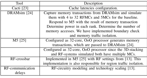
Cacti [23] Cache latencies configuration.
DRAMsim [24] Capture memory transactions from DRAMsim and simulate them with 4 to 32 RFMCs and 5MCs for the baseline. Respond to M5 with the result of memory transaction Determine power in each rank. Determine the number of memory accesses. We have implemented boundary check
and memory traffic isolation.
M5 [25] Configured as 32-core, OoO processor generates memory transactions, which are passed to DRAMsim [24]. Configured as 32-core, OoO processor since the 3D-stacking
and RF-systems simulated both have multiple MCs. RF-crossbar Implemented in M5 [25] with RF settings from [13]. This
implementation is also responsible for region traffic isolation. RF-communication RF-circuitry modeling and technology scaling [13].
[image:7.612.314.572.52.189.2]delays
TABLE I: Methodology: tools and description
has the following ports: control, input, output, and throughout. If control signal is ”1”, incoming data from the input port is sent to the throughout port. And, if control signal is ”0”, incoming data is not propagated to the throughout port.
Using these logical operations implemented with optical inverter, we propose straightforward control circuits to be connected to the optical logical control signal of the inverter responsible for: (i) selecting cache addresses which belong to the address range of the created regions; and (ii) filtering cache addresses which do not belong to the specified range.
To select cache addresses that belong to a region, the control operation circuit should be coupled to the optical control signal so that these signals are sent to the throughout port. Conversely, for addresses which do not belong to a specified region address range, the control should send them to the drop port.
A general description of the operation of the crossbar is
illustrated in Figure 2a. Theconf ig(configure) block contains
registers and required operations in order to configure the crossbar operation. This block takes the cache addresses of different ranges as inputs while it generates the configuration
signal (conf as described in detail in Figure 2b) for that ring
resonator block as output. The circuits present in this block are mainly composed by simple comparator circuits. The complex-ity involved in this block - which participates to the operations of creation, isolation, and reorganization - is not significant in terms of overall circuits complexity. Though beyond this study, overall complexity grows linearly with the number of regions, and requires a trade-off investigation between low area overheads and the number of regions required.
The configuration signal of the conf ig registers block
in Figure 2a is connected to the control signal (conf)
of the ring resonator as depicted in Figure 2b. This
sig-nal is used to implement the address mod M Cs and
address mod (M CsDedicatedT oRegion) operations. We detail this implementation in the next section.
IV. EXPERIMENTALRESULTS
We start this section by describing the methodology em-ployed in experiments performed, followed by presenting and discussing the results obtained.
A. Methodology
the time overheads of the optical reconfiguration process are significantly smaller and the hardware unit responsible for it is of low-magnitude area overhead.
Before describing the methodology adopted, the baseline in terms of number of MCs for the regions is explained. We utilize the number of MCs in real systems as the baseline MC count for CPU, GPU, and heterogeneous regions, to resemble real systems. An in-depth research on heterogeneous systems currently available indicates that current heterogeneous sys-tems [1] have 2MCs, which is adopted as the baseline.
For a global view of the methodology considered, all sim-ulators employed and their descriptions are listed in Table I. The general methodology employed in this paper is adopted from [16], applied to each type of region. Bandwidth-bound applications are used in order to evaluate the regions, since the primary goal is to target bandwidth.
Region-related concepts are implemented as follows. Re-gions boundary check is included in DRAMsim [24], while network traffic isolation in M5 simulator [25]. Region bound-ary check is basically implemented with the address-mod-related calculations previously explained in Section III-E1. As previously mentioned in III-A, memory traffic isolation is controlled via user/OS tasks. Region identification is assumed when the user/Linux tasks are created on M5 simulator [25] or at the creation of GPU tasks in GPGPUsim [26], whilst network traffic isolation is in M5 by filtering packets that do not belong to that region (range of memory addresses previously explained). Reorganization region identification, boundary checking and network traffic isolation are imple-mented similarly to the creation operation.
To evaluate the memory behavior of the CPU regions, we combine the M5 [25] and the DRAMsim [24] simulators as follows. To predict the behavior of future heterogeneous mul-ticores, a 32-core processor model is created in M5 [25], and as memory transactions are generated in M5 upon benchmark execution, these are captured in DRAMsim [24] which is set with multiple MCs, each associated with its own rank. Next, DRAMsim responds to M5 with the result of each transaction. In this environment, we confirm the appropriate calibration of the bandwidth in one rank: about 2.0 GBytes/s as indicated in the manuals [27]. For the CPU regions, we perform an analysis of regions with MC counts ranging from 2MCs (baseline) to 32MCs. We should highlight that our investigation explores up to 32MCs, significantly larger than currently used counts in typical microprocessors.
In this evaluation, we have further utilized a CPU ISA based on Alpha processor, set as a 4-way issue OOO core similar to high performance microprocessors such as [1], at 3.0 GHz with MCs operating at 1.5 GHz as in typical microprocessors [28]. We used Cacti [23] to obtain cache latencies and adopted miss status holding register (MSHR) counts similarly to current microprocessors [28]. In order to be able to increase the number of cores, these are connected as a clustered architecture, and we utilize L2-MSHR structures [29] that can be replicated to achieve higher memory bandwidths, while we assumed an L2 similar to what can be found in current microprocessors. However, instead of a shared L2, we employed a private L2 to avoid L2-cache sharing effects which would affect memory bandwidth and IPC measurements.
To model the behavior of GPU regions with a set of assigned MCs, we used the GPGPUsim [26] simulator which
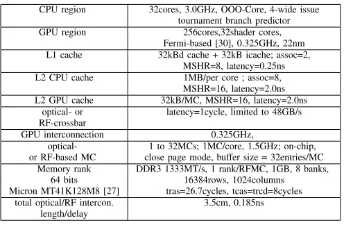
CPU region 32cores, 3.0GHz, OOO-Core, 4-wide issue tournament branch predictor GPU region 256cores,32shader cores,
Fermi-based [30], 0.325GHz, 22nm L1 cache 32kBd cache + 32kB icache; assoc=2,
MSHR=8, latency=0.25ns L2 CPU cache 1MB/per core ; assoc=8,
MSHR=16, latency=2.0ns L2 GPU cache 32kB/MC, MSHR=16, latency=2.0ns
optical- or latency=1cycle, limited to 48GB/s RF-crossbar
GPU interconnection 0.325GHz,
optical- 1 to 32MCs; 1MC/core, 1.5GHz; on-chip, or RF-based MC close page mode, buffer size = 32entries/MC
Memory rank DDR3 1333MT/s, 1 rank/RFMC, 1GB, 8 banks, 64 bits 16384rows, 1024columns Micron MT41K128M8 [27] tras=26.7cycles, tcas=trcd=8cycles
[image:8.612.318.566.51.213.2]total optical/RF intercon. 3.5cm, 0.185ns length/delay
TABLE II: modeled architecture parameters
already contains a module that implements multiple DDR-based MC-systems. Memory transactions are generated by the multiple GPU L3 caches and simulated in the memory module of GPGPUsim. The GPU architecture modeled follows the Nvidia Fermi architecture [30]. Similarly, we explore a variable number of MCs from 2 to 32. Furthermore, we adopted similar GPU cache settings [30] to GPU processors keeping proper (as further described) RF-intercommunication delays [13] between GPU L3 caches and the crossbar.
The most straightforward way to perform a detailed simu-lation of the bandwidth impact on a heterogeneous region is to employ a simulator for heterogeneous systems. However, the higher computational complexity of these simulators can lead to significant higher simulation times. Instead, we propose a methodology that independently utilizes CPU and GPU simulation infrastructures and combines them to determine the impact of the increase of the number of MCs in heterogeneous regions.
Similarly to Marino’s report[12], we employ ranks with proper DDR-family settings in terms of timings, protocols, control-data signal separations, and organization - in terms of banks, rows, and columns. Timing parameters are based on 1GB DDR3 rank, based on Micron model MT41K128M8 [27]. Each MC is associated with one of the previous ranks, i.e., 32 MCs are associated to 32 ranks. The sets of 32 MCs/32 ranks are coupled to 32 cores in order for the bandwidth to feed these cores whilst keeping a balanced proportion core:MC as 1:1. Furthermore, since each MC is connected to a different DDR rank, cache lines interleaved along MCs are actually interleaved along different ranks. Additionally, closed-page
mode was used aimingRAM ON to target low energy usage
on a server environment.
To model communication delays, Chang validated modeling
methodology et al. [13] is followed: the optical and
RF-interconnection delays involved are of a similar order of magnitude by signals delays when traversing the estimated
distance (e.g.,2.5cm [12]).
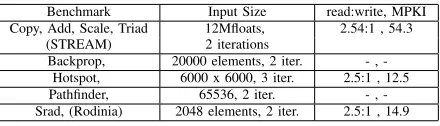
Benchmark Input Size read:write, MPKI Copy, Add, Scale, Triad 12Mfloats, 2.54:1 , 54.3
(STREAM) 2 iterations
[image:9.612.62.282.52.115.2]Backprop, 20000 elements, 2 iter. , -Hotspot, 6000 x 6000, 3 iter. 2.5:1 , 12.5 Pathfinder, 65536, 2 iter. , -Srad, (Rodinia) 2048 elements, 2 iter. 2.5:1 , 14.9
TABLE III: benchmarks and input sizes
Crossbar upper bandwidth was designed so that (i) as the number of ranks (that follow the number of MCs) is increased, total bandwidth is not restricted, and (ii) to approximate actual delays [13]. Similar settings are also valid for connections to GPU L2 caches.
Given that the number of regions in benchmarks evaluated is of reduced magnitude (assumed maximum of 32 regions), boundary registers and comparators setting delays involved in the creation, isolation, and reorganization operations are of significantly reduced magnitude when compared to cache delays and RF-interconnection.
Next, the methodology employed to obtain power and energy-per-bit is discussed. To obtain the total power, DRAM-sim power models are considered, following the Micron formu-lation [27] which includes the power spent on all ranks and interconnection. To determine the total energy-per-bit spent, we adapt the methodology described in [14] to the magnitudes obtained in DRAMsim power infrastructure (which are also based on the Micron formulations [27]) and combine them with the memory bandwidth extracted from the benchmark, if designed to measure bandwidth, the number of memory transactions (DRAMsim or GPGPUsim) and execution time, if otherwise. Table II contains all architectural parameters.
Benchmarks selection followed the methodology employed in [12]. It consists of a selection of medium and high bandwidth-bound benchmarks with a significant number of misses per kiloinstructions (MPKI) to evaluate the memory system: the STREAM [31] suite designed to measure memory bandwidth, decomposed in its four sub-benchmarks (Copy, Add, Scale, and Triad) as well as Backpropagation, Hotspot, Pathfinder and Srad from Rodinia suite [32].
In addition, we exemplify some region operations (creation and reorganization), assuming they happen as a sequence of task termination followed by the creation of a new one, as illustrated next. In experiments, we assume up to 32 different regions since we have 32 cores.
Table III summarizes selected benchmarks, input dataset sizes, read-to-write rate, and L2 MPKI obtained. In all bench-marks, parallel regions of interest were executed until comple-tion. All input datasets are larger than the total rank memory size, which guarantees that all memory space is stressed. Average results are calculated based on harmonic average.
To measure the implications on performance, it is proposed:
• to measure instructions per cycle (IPC) as an indication
of throughput/performance;
• to measure bandwidth gains on each type of region
(CPU, GPU, and heterogeneous);
• to perform an investigation of the degree of memory
parallelism for each type of region by performing an investigation of the bandwidth gains from the baseline (2 MCs) to the maximum number of MCs (32 MCs);
• to determine the maximum bandwidth of a CPU, GPU,
and heterogeneous region as top boundary magnitudes;
• to be able to determine the maximum bandwidth, each
selected benchmark is scheduled to each individual type of region, with all MCs dedicated to that same one;
• to measure bandwidth for benchmarks not necessarily
designed to measure bandwidth (all from the Rodinia suite [32]) by dividing the number of bytes the memory system effectively transfers - obtained in the simulation infrastructure correspondent to memory read and write operations - by the execution time;
• to allow the creation of regions before proper
bench-marks’ executions in those regions.
B. Determining the bandwidth of a heterogeneous region Since a CPU region contains solely CPU cores, we define the memory bandwidth supplied to each CPU core as:
BwCP U = Bw
CP U cores (6)
where Bwis the effective bandwidth according to equation 3
and CP U cores represents the total number of CPU cores present in that region. Similarly, for a GPU region with
GP U cores- clusters of cores (each cluster with an associated MC), bandwidth can be expressed as:
BwGP U = Bw
GP U cores (7)
Now, a heterogeneous region created with cores from both CPU and GPU regions has a maximum bandwidth expressed as:
Bwhet= Bw
CP U cores + GP U cores (8)
Using Subsection III-C considerations and:
CP U cores +GP U cores > CP U cores and (9)
CP U cores +GP U cores > GP U cores (10) We can derive that:
Bwhet= BwCP U ∗CP U cores
CP U cores + GP U cores, and (11)
Bwhet= BwGP U ∗GP U cores
CP U cores + GP U cores (12)
Therefore, by analyzing equations 8, 9, and 10, we demon-strate that the bandwidth of a heterogeneous region is lower than the bandwidth of the respective CPU and GPU re-gions (with similar MC counts) and can be calculated us-ing the latter equations. Thus, to determine the bandwidth of the heterogeneous region, without loss of generality, we select the CPU region bandwidth results and apply the factor
CP U cores / (CP U cores + GP U cores) to determine it next.
C. Bandwidth
0 2 4 6 8 10
2 4 8 16 32 2 4 8 16 32 2 4 8 16 32 2 4 8 16 32 2 4 8 16 32 2 4 8 16 32 2 4 8 16 32 2 4 8 16 32
Bandwidth: normalized to the baseline (x times)
MCs available in the region
Bandwidth - CPU region baseline - 2 MCs
2 MCs 4 MCs 8 MCs 16 MCs 32 MCs
Add Copy Scale Triad
Backprop
Hotspot
Pathfinder
Srad
0 2 4 6 8 10 12 14 16
2 4 8 16 32 2 4 8 16 32 2 4 8 16 32 2 4 8 16 32 2 4 8 16 32 2 4 8 16 32 2 4 8 16 32 2 4 8 16 32
Bandwidth normalized to the baseline (x times)
MCs available in the region Bandwidth - GPU region
"baseline (2 MCs)" 2MCs 4 MCs 8 MCs 16 MCs 32 MCs Add
Copy
Scale Triad
Backprop.
Hotspot
Pathfinder
Srad
0 2 4 6 8 10
2 4 8 16 32 2 4 8 16 32 2 4 8 16 32 2 4 8 16 32 2 4 8 16 32 2 4 8 16 32 2 4 8 16 32 2 4 8 16 32
Bandwidth: normalized to the baseline (x times)
MCs available in the region
Bandwidth - Heterogeneous Region 2 MCs
4 MCs 8 MCs 16 MCs 32 MCs baseline - 2 MCs
Add Copy Scale Triad
Backprop
Hotspot
Pathfinder
Srad
2-MC region
4-MC region
8-MC region
16-MC region
[image:10.612.56.545.91.659.2]32-MC region
0 2 4 6 8 10 12 14
2 4 8 16 32 2 4 8 16 32 2 4 8 16 32 2 4 8 16 32 2 4 8 16 32 2 4 8 16 32 2 4 8 16 32 2 4 8 16 32
IPC normalized to the baseline (x times)
MCs available in the region
IPC - CPU region
2 MCs 4 MCs 8 MCs 16 MCs 32 MCs baseline - 2 MCs
Add Copy Scale Triad
Backprop
Hotspot
Pathfinder
Srad
0 2 4 6 8 10 12 14 16 18
2 4 8 16 32 2 4 8 16 32 2 4 8 16 32 2 4 8 16 32 2 4 8 16 32
IPC normalized to the baseline (x times)
MCs available in the region
IPC - GPU region
2 MCs 4 MCs 8 MCs 16 MCs 32 MCs baseline - 2 MCs STREAM Average
Backprop
Hotspot
Pathfinder
[image:11.612.55.548.57.454.2]Srad
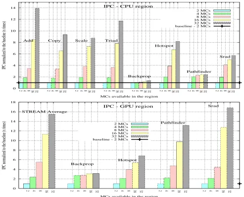
Fig. 4: top to bottom, IPC versus number of MCs on Fig 4a for CPU regions (top) and on Fig 4b for GPU regions (bottom); STREAM Average: average IPC over STREAM benchmarks.
Our findings show that the largest bandwidth achieved is for Add, where for 32 MCs it is about 9x times faster than the baseline, while the smallest one is observed with Pathfinder, where the 3configuration is 2.2x faster than the 2MC-configuration. Similar to the number of MC’ settings found in [12], the selection of a larger input dataset allows larger memory data transfers for Pathfinder in the CPU region. We also observe that for the Copy and Scale benchmarks, the bandwidth saturates at 16 MCs. By analyzing infrastructure simulation statistics, we observe that this effect happens due to the bandwidth limitations of the crossbar (Table II, 48GB/s). By applying different degrees of parallelism through the use of different numbers of MCs, tasks executed in CPU regions yield significant bandwidth improvements when compared to the baseline as the number of MCs (parallelism) is increased. As shown in Figure 3b, just like with CPU regions, GPU regions present similar trends in terms of augmenting MCs: for all the benchmarks in the STREAM suite [31] and for all the benchmarks in the Rodinia suite [32], bandwidth is improved for the different degrees of memory parallelism. The
best bandwidth result happens for Copy, which for the 32-MC configuration, is 14.1x higher than the baseline. The worst result (2.3x faster than the baseline) happens for Hotspot with the 32MC-configuration.
The largest bandwidth magnitude in both types of regions occur for the largest number of MCs, which is obtained accord-ing to the behavior observed in equation 2. By comparaccord-ing CPU to GPU regions, bandwidths are larger on the GPU ones, since their architecture [30] demands higher memory bandwidth.
For STREAM suite [31], bandwidth behavior in both types of regions increases proportionally to the number of MCs available to that region. However, in Rodinia suite [32], it is interesting to observe that some benchmarks present con-sistent increase on bandwidth behavior, while others do not. For example, Backpropagation and Srad bandwidths increase proportionally with the number of MCs, while others such as Hotspot and Pathfinder display the opposite behavior.
mentioned suites but not to explore benchmark parallelization techniques in these different architectures. Furthermore, ac-cording to Marino and Li’s report[15], to have a fair compari-son between Hotspot and Pathfinder on these different architec-tures, we should have both programs parallelized using similar techniques to provide the best possible bandwidth, which is not the case. For example, in the case of a GPU architecture, the use of GPU caches are controlled via programming, which is not the case of the Rodinia benchmarks [32], where CPU programs use OpenMP and whilst GPU programs use CUDA. Highlighting its importance, bandwidth improves in all types of regions upon increasing the number of MCs. In addition, this bandwidth improvement is valid for a significant diversity of benchmarks for either CPU or GPU regions.
To estimate the bandwidth of a heterogeneous region, 32 cores (Table II) are used for the CPU regions, 32 shader cores ((Table II) for GPU regions, CPU bandwidth results in Figure 3a are used as inputs to equations 11 and 12. This estimation is illustrated in Figure 3c. Instead of using the baseline of the heterogeneous region as 2MCs, we use the one from the homogeneous so that, bandwidth reduction can be easily observed. The results show that bandwidth also increases when the number of MCs is augmented.
D. Throughput or Processor Performance
We have measured the number of instructions per cycle (IPC) in order to estimate processor performance improve-ments. Figures 4a and 4b illustrate IPCs obtained in the experimentation. As a general observation, for either CPU or GPU regions, IPC increases follow bandwidth increases as the number of MCs is increased. IPC largest magnitudes are very significant, about 14x for CPU regions, and 17x for GPUs. The best results obtained are for STREAM suite and Hotspot in CPU regions, while Srad, STREAM, and Pathfinder in GPU regions. The worst IPC gains obtained are present in Backpropagation either in CPU and GPU regions.
E. Latency
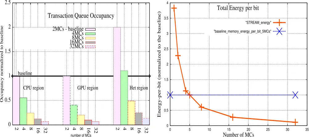
Since bandwidth and latency are related [20], the effects of several degrees of parallelism, can be observed in terms of latency, which are measured as transaction queue average occupancy. The results of these measurements are shown in Figure 5a. Compared to the baseline, transaction queue occupancy is respectively reduced by up to 93.3% in CPU regions, up to 93.1% in in GPU regions, and up to 86.6% in heterogeneous regions. Heterogeneous reduction is lower since this type of region presents a larger memory contention (more cores issuing memory requests). In all cases, occupancy reduction demonstrates significantly lower levels of memory interference.
Similar to the formulation developed to obtain bandwidth dependency between CPU and GPU regions in heterogeneous regions - represented by equations 11 and 12, we obtain latency by using a similar proportionality factor. This estimation is shown in Figure 5a, where significantly higher levels of latency exhibits the behavior previously predicted.
To summarize, we observe that for isolated CPU or GPU regions, as well as for merged ones, an increase on the number of MCs benefits performance by improving memory parallelism. Combined CPU/GPU sets need more bandwidth to achieve the same levels of speedup of isolated ones.
F. Creation, Isolation, and Reorganization
In this subsection, operations of creation, isolation, and reorganization are discussed. Various degrees of parallelism, starting from 2MCs (baseline) to 32MCs were tested. To perform the evaluation, each region is created with a different number of MCs dedicated to it. For example, in Figure 3d, each vertical bar corresponding to a MC configuration at the X axis corresponds to a different region set with different numbers of MCs. These regions were created or reorganized assuming the user requested the experimented MC settings (X axis). Similarly, different regions are present when performing the evaluation of GPU regions.
Figure 3d illustrates the reorganization operation assumed (Subsection IV-A) as a sequence of tasks created and termi-nated. In this example, after a first region is created, it is reorganized to have the number of MCs double as the previous. This process is repeated until the maximum number of MCs is achieved, after which it is terminated.
Results showing bandwidth improvements for each type of region demonstrate that bandwidth significantly increases with an increase of the number of MCs. Isolation property backs up these results as showed in Subsection III-C, otherwise regions would present much larger memory and network traffic for CPU, GPU, and heterogeneous regions.
G. Energy
Due to space considerations, only energy-per-bit for STREAM benchmarks are shown in Figure 5). This figure shows that energy-per-bit decreases as the number of MCs increase, which follows Marino’s report [12] and can be intu-itively explained by dividing power usage over proportionally increasing bandwidths. In addition, as noticed in the previous (section) latency analysis, memory system is active for a lower amount of time, thus reducing the energy-per-bit spent. Though with different slopes, similar behavior is observed for the remaining benchmarks.
H. Important Points: Design Guidance Outcomes
Very importantly, as previously mentioned in Section I, even adopting optical or RF technology, as a guide to fu-ture heterogeneous industry processors design, the drop in bandwidth/latency and IPC is significant roughly 60% -when having more heterogeneous processors, as observed in Figures 3a to 3d and previous homogeneous/heterogeneous results. Furthermore, different regions allow the reduction of interference (shown as lower levels of occupancy and higher levels of memory bandwidth).
We conclude that the contention bottleneck on the PCI e-bus due to communication between traditional CPUs and GPUs is shifted to the memory system in heterogeneous microprocessors is still present in scalable memory systems given the drop in bandwidth/IPC.
0 0.5 1 1.5 2 2.5
2 4 8 16 32 2 4 8 16 32 2 4 8 16 32
Occupancy normalized to baseline
number of MCs
Transaction Queue Occupancy
baseline
CPU region GPU region Het region
2MCs - baseline 4MCs 8MCs 16MCs 32MCs
0 0.5 1 1.5 2 2.5 3 3.5 4
0 5 10 15 20 25 30 35
Energy-per-bit (normalized to the baseline)
Number of MCs
Total Energy per bit
[image:13.612.53.554.57.279.2]"STREAM_energy" "baseline_memory_energy_per_bit_5MCs"
Fig. 5: left to right: Fig 5a transaction queue occupancy and Fig 5b energy-per-bit versus number of MCs.
V. SENSITIVITYANALYSIS
Our sensitivity analysis is designed to assess the impact of several key aspects: (i) number of memory MCs and cores; (ii) creation, isolation, and reorganization operations; (iii) minimum acceptable performance degradation, and (iv) benchmarks.
N umberof M CsandN umberof Cores:different levels of memory parallelism are estimated via experimenting different number of MCs assigned to each region (2 to 32MCs).
Via properly designed pins, optical/RF technologies allow the use of larger MCs, which potentially enables a larger num-ber of cores. Aiming the highest memory parallelism possible, a higher magnitude of MCs compared to cores is employed to maintain the ratio core:MC (we used 32MCs/32ranks).
If the number of cores in either CPU, GPU, and hetero-geneous regions is increased, pairs of MCs and ranks can be augmented to match the core:MC proportion as previously discussed. Using this strategy, the augment of the number of MCs to larger magnitudes is an attractive solution for either homogeneous or heterogeneous systems with larger numbers of cores. In Marino and Li’s report [15], the number of MCs selected is restricted to 8MCs, and we clearly went further up to 32MCs in order to explore larger amounts of MCs.
Creation, Isolation, andReorganizationOperations :
these operations require the crossbar network to be configured accordingly. Regardless of the type of MC interface (opti-cal/RF), the registers and XORs to perform modulo operations, as well as the registers and comparators required to perform region boundaries grow linearly with the number of regions. As previously mentioned, a trade-off investigation between the area of these elements and the number of required regions in CPU, GPU or heterogeneous applications is required to establish bandwidth design requirements.
AcceptableP erf ormanceDegradationandCrossbar:As we have demonstrated, the increase on the number of MCs for memory-bound applications increases bandwidth whilst
reducing interference. In order to be used with a larger number of MCs, cache-related structures should allow a larger amount of memory traffic through, which can be achieved via employing a low-transmission delay optical/RF crossbar set as in reports [12][16]. As we have multi/many cores, by utilizing replicated MSHR structures [29], we guarantee that traffic is not restricted or reduced. Both previous conditions are likely to avoid significant bandwidth degradation.
Benchmarks:The benchmarks utilized here are composed of bandwidth-bound applications to evaluate the behavior of each type of region, as well as several degrees of memory parallelism via a different number of MCs. However, if lower intense (lower misses per kilo instructions - MKPI) bound applications or benchmarks that are not bandwidth-bound are employed, the benefits of the increase on the number of MCs are likely to be comparatively lower.
A design space exploration can determine the ratio between the number of MCs - for CPU-, GPU-, or heterogeneous-regions - and the number of cores to achieve a desired bandwidth. Such exploration is beyond this study and funda-mentally depends on the bandwidth level and QoS aimed.
VI. RELATED WORK
The work by Muralidhara et al.[5] proposes to map
appli-cations data that are likely to severely interfere with each other on different channels and combine channel partitioning with
scheduling.RAM ON is orthogonal to this work, in the sense
that as it aims to reduce memory interference on heterogeneous regions, different numbers of channels are created. However,
RAM ON could be coupled to Muralidhara’s techniques with different scheduling and channel partitioning.
In the work by Xie et al. [6], memory banks are
dy-namically partitioned according to thread utilization profiling.
Configurable memory regions inRAM ON with the isolation
could be combined to Xieet al.’s approach in order to create configurable memory regions based on the profile utilization.
The research by Janzet al.[7] proposes a software
schedul-ing framework where an application interacts with the OS to determine its memory address space dynamic footprint
utilization. Instead,RAM ON proposes dynamic creation and
reconfiguration of regions with different number of MCs in order to reduce memory interference, according to the OS or the application (CUDA), where Janz’s framework fits.
Ausavarungnirun et al. [8] propose a different MC
man-agement which groups memory requests according to row-buffer locality first, then inter-application scheduling, and
finally FIFO scheduling.RAM ON’s approach is orthogonal
to Ausavarungnirunet al.’s approach, where individual regions
creation or reconfiguration could be triggered by the latter.
Kayiranet al.[21] propose an integrated management
tech-nique that alleviates the GPU contention on shared resources
when on a heterogeneous environment. AlthoughRAM ON’s
techniques of isolation and creation reduce the interference
of memory regions, by reconfiguring the crossbar, Kayiran et
al.’s management technique could be coupled toRAM ON in order to create/reconfigure regions.
Jeong et al. [9] investigate a QoS mechanism that keeps
GPU workloads to dynamically adapt CPU and GPU priorities.
RAM ON’s approach is orthogonal to the latter, i.e., as it could be used to create/reconfigure regions to fit different bandwidth needs using different MC settings according to the QoS priority.
Usui et al [33] extended Jeong et al.’s approach [9] to hardware accelerators trading off QoS applications bandwidth
and latency. RAM ON is orthogonal to the latter and could
change the number of MCs in regions to match different hardware accelerators and trade-off latency/bandwidth.
Memscale [18] is a set of software and hardware mecha-nisms which includes OS policies and hardware power tech-niques to trade-off memory energy and performance in typical
memory systems. RAM ON shares with Memscale the
simi-larity of adopting bandwidth estimations independently. In the former, each MC bandwidth is estimated independently, whilst in RAM ON bandwidth is estimated on each independent
region. Nevertheless,RAM ONcan have different regions and
each of them can have a variable number of MCs assigned according to the bandwidth demands.
The investigation by Zhang et al. [34] proposes the
uti-lization of a variation-aware MC scheme that explores the utilization of memory chunks with different access times.
RAM ON’s approach is orthogonal to the former approach, since the proposed scheme can potentially explore not only dif-ferent variation aspects but also difdif-ferent bandwidth demands. Similarly, we share the same interface and RF-technology principles of RFiop [16] and RFiof [12], as well as the optical technology approaches [14] when increasing the number of MCs. In this report, the concept of regions and their properties are used to evaluate the impact of different degrees of memory parallelism for different types of regions.
The work by Marino and Li [15] approaches multicore bandwidth challenges via the increase of the number of MCs in traditional digital-based embedded systems, which has a restricted number of counts due to high I/O pin usage.
Differ-ently,RAM ON approaches scalability of MCs using
optical-and RF-based interfaces that enable the use of a significant
larger number of MCs than in traditional digital systems as
in the report [15]. Additionally, in RAM ON MC region
awareness is highlighted, whilst presenting a new low-area overhead optical-crossbar design that enables the creation of regions with isolation/reorganization properties. Moreover, a significant extension of the bandwidth model initially proposed in [15] is performed with a new detailed experimental inves-tigation that considers energy and processor (instruction per cycle - IPC) as a measure of throughput/performance for a significant larger number of cores.
VII. CONCLUSIONS ANDFUTUREWORK
In this investigation, RAM ON approaches heterogeneous
multicore memory bandwidth demands via creating different regions of memory for CPUs and GPUs, or combined hetero-geneous CPU/GPU regions, where different levels of memory parallelism are explored via different numbers of MCs. In order to afford these different levels of memory parallelism, each region of CPU, GPU, or heterogeneous should provide
isolation, i.e., should have its own memory space. Isolation
segregates memory accesses by regions and avoids memory interference from other regions, also avoiding larger amounts of memory contention and related memory traffic. The use of a lower number of pins of optical- and RF-based interfaces
enables RAM ON to achieve significantly higher levels of
memory parallelism when compared to traditional memory systems with low amounts of MCs. Our findings show that a larger number of MCs contributes to performance improve-ment more than region isolation.
An important open issue for industry or research design is to face a performance represented by bandwidth or IPC -drop of about 60% when using heterogeneous cores sharing the same memory address space, even when using a high scalable memory design.
As observed in this research, the bandwidth improvement has a direct impact on processor performance improvement. Since different algorithms demand significantly different de-grees of memory parallelism, we leave the integration of
RAM ON to user/OS scheduling strategies [5][6][7] as well as a detailed trade-off of the crossbar area/circuits based on application behaviors are directions for future research.
Given that memory bandwidth challenges is a very active area of investigation, the evaluation of the proposed user-feedback scheduling for application with constant and variable
demanding bandwidth proposed in Section III-A is also
planned. As future challenges, an investigative analysis of the trade-offs involved in the crossbar when switching regions operations (creation, isolation, and reorganization) could be
coupled with RAM ON dynamic regions determination and
reconfiguration required in IoT, scientific and commercial applications aiming to improve bandwidth. Moreover, we plan to evaluate regions when introducing other types of cores which run applications with different memory bandwidth re-quirements.
VIII. ACKNOWLEDGEMENT