DESIGN AND DEVELOPMENT OF A FLYING ROBOT WITH IMPROVED
TIME CONSTANT IN RESCUE ACCIDENT VICTIMS
Muhammad Mahbubur Rashid1 and Md. Sazib Mollik2
1Department of Mechatronic Engineering, Faculty of Engineering, International Islamic University Malaysia, Jalan Gombak, Kuala Lumpur, Malaysia
2Department of Manufacturing and Material Engineering, Faculty of Engineering, International Islamic University Malaysia, Jalan Gombak, Kuala Lumpur, Malaysia
E-Mail: [email protected]
ABSTRACT
The goals of this flying robot are to provide an accurate and precise search, rescue, exploration and saving of accident victims and also to reduce rescue time constraint. The major task in designing this robot is able to recognize the human body figure and detect the temperature of human body while searching the victim. At first, the design of robot’s body will use base on coaxial helicopter. After that, system and recognition of human body figure system which uses the machine vision knowledge. Moreover, obstacles avoidance system, navigation system and flight level measurement system, communication system and temperature measurement system also included.
Keywords: design of robot’s body, coaxial helicopter, human body figure, temperature measurement.
INTRODUCTION
Autonomous robots are robots that can perform required tasks perfectly without a continuous human monitoring, maintenance and guidance. Different robots can be autonomous in different ways or methods. An unmanned aerial vehicle (UAV) is the prominent part of a whole system that is necessary to fly the aircraft. Even though there is no pilot physically present in the aircraft, this doesn’t mean that it flies by itself autonomously. In many cases, the crew responsible for a UAV is larger than that of a conventional aircraft [1].
At present, a lot effort is being made to develop proficient Unmanned Aerial Vehicles (UAV). Small size UAVs are very promising stage for monitoring, inspection, and urgent situation support in remote area. Unmanned helicopter is appropriate for observing and inspection because of its hovering capability [2, 4]. Helicopter has been the sympathetic stage for UAV progress. However, the developing method and regulating scheming of a helicopter involves a lot of attempt since it is difficult and very unsteady method [5].
An unmanned aerial vehicle (UAV) is operating without piloted aircraft. UAVs operation can be controlled by remote or fly autonomously basis on pre-programmed flight plans or it is very complex progressive systems. At present UAVs are used this device varies number of military roles, including reconnaissance and attack. They are also try to use it such a small work but increasing number of civil applications such as fire fighting, when a human will face any problem. UAVs are always ready to face any missions and others. UAVs are classified into six purposeful categories object and decoy are as long as ground and aerial gunnery a goal that simulates an adversary helicopter or missile, reconnaissance's are supplying battlefield cleverness, combat are prepared for attack and try to show their capability for high-risk
missions, logistics a UAVs exclusively organized designed for cargo and logistics function, research and development try to used UAV technologies for advance enlarge to be incorporated into ground deployed UAV aircraft and lastly civil and commercial UAVs particularly deliberate for civil and commercial applications [6] .
To obtain the began mission, the vehicle required to have a particular level of autonomy to operate its stability following a intended path tributary embedded steerage, direction-finding and organize algorithm [7]. Flying robot (unmanned helicopter) can easily perform hovering, take-off, and land vertically compared to the fixed wing aircraft. Therefore the flying robot has the capability of being to utilize in various fields such as dangerous field, disaster field and so on. In order to use the flying robot in dangerous fields and disaster fields, it will develop four rotor flying robots [8].
DESIGN DEVELOPMENT AND COMPONENT SELECTION
For robot’s body design, here it will use the concept of coaxial helicopter design. The reasons for this are coaxial helicopter which is the most fashionable design that come to brainpower when human assume regarding electric RC helicopters and for excellent daily work too. Those twice-bladed helicopters are recognized by bringing hordes of latest fanatic into the planet of RC aviation [2].
which the helicopter's nose is pointing at more theoretically known as the yaw. To organize the yaw, the pilot will try to changes the angle of the tail rotor.
Figure-1. Coaxial helicopter.
Infect, these fliers have two rotors, one on top of the other rotating in parallel orders. Consequently, the torque generated by every rotor cancels exposed one another. When such exploit is attached with two rotors' lift and it is complementing with each other outcome in the unusual steadiness and balanced skill. Because balanced is one of the major mechanism of a helicopter's flight easier to hover or balance is almost synonymous to easier to fly. Controlling the yaw in this set of connections becomes only a matter of slowing or speeding up one of the two rotors [3].
Figure-2. Complete design of flying robot.
FABRICATION AND TESTING
In the process of developing flying robot, several process and testing have been done in order to combine the mechanical part and electrical part according to the finalized design. The process involved in constructing the prototype assembling the robot body, position of sensor and electronic circuit. The body of robot is main
mechanical component for flying robot. The body is designed to be in cylinder shape because it is able to support all the circuit and battery. The base is made by from the acrylic and aluminum because of its lightness in weight and easy to make and design a shape. For obstacles avoidance, suitable position of ultrasonic sensor is important in order to detect obstacles accurately and widely coverage [9].
Ultrasonic sensor is a sensor that used mainly in the areas of testing and inspection, especially for non-destructive testing and for sensing distance, level, speed and axial medical devices, dimensional gauging and robotic applications. The ultrasonic sensors are deliberate for use in customary business applications concerning presence discovery [2]. For this robot a combination and integration of circuit is required for microcontroller that control all the sensor and actuator for robot, circuit for controlling the brushless DC motor and circuit for sensor.
Chart-1. Operation flow chart of flight level measurement system.
For graphical user interface we use MATLAB software graphical user interface is an interface that used for communicate the user and the robot [3].
MATHEMATICAL CALCULATION
Let us consider earth fixed frame E and body fixed frame B, as seen in Figure-4. The centre of mass and the body fixed frame origin are assumed to coincide. Using Euler angles parameterization, the airframe orientation in space is given by a rotation R from B to E, where R € SO3 is the rotation matrix. The dynamics of a rigid body under external forces applied to the centre of mass and expressed in the body fixed frame as shown in 6 and 8 are in Newton-Euler formalism:
F I
mV V
I mI x
. . 3
3 0
0
Where the inertia matrix V the body linear in the frame system Figure-3, the equations of motion for speed vector and w the body angular speed. It can be written as
Figure-3. Quad rotor configuration, frame system with a body fixed frame B and the inertial frame E.
a
J
J
R
R
b
RF
m
.
.
.
.
.
(2)The first-level approximate model (3) of the Quadrotor can be rewritten as:
a e J I I R R m b e R ger
3 2 . . . . . 3 3 (3)
The torque applied on the vehicle's body along an axis is the difference between the torques are generated by each propeller on the other axis
2 3 2 1 2 4 2 2 2 1 2 3 2 2 2 4d
lb
lb
a
(4)The full Quad rotor dynamic model with the x, y and z motions as a consequence of a pitch or roll rotation is:
4 2 1 1 1 ) cos (cos 1 1 cos sin sin sin cos 1 1 sin sin cos sin cos 1 3 1U
I
I
I
U
I
J
I
I
I
z I z y x I y r y x z y U x I x I r J x I z I y I U m g z U m y U m x
(5)Then, the system's inputs are posed U2, U3, U4 and R a disturbance, obtaining:
The rotors are driven by DC-motors with the well-known equations [10]
d m m m edt
d
J
K
Ri
u
dt
di
L
(6)As we use a small motor with a very low inductance, the second order DC-motor dynamics may be approximated by:
u
R
K
R
k
dt
d
J
m d m mm
2(7)
By introducing the propeller and the gearbox models, the equation (8) may be rewritten:
The equation (9) can be linearized around an operation point [1]
t k
t
m m
J
r
d
C
B
J
r
d
A
with
C
Bu
A
from
the
to
m 3
2 0 1
3 0 1
0
,
,
2
:
RESULTS AND DISCUSSIONS
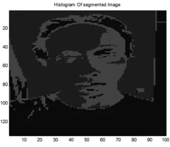
For recognition system, MATLAB software has used for coding and Graphics User Interface (GUI). Process that it will use for image processing is called as segmentation process in Machine Vision. Segmentation process is a process for computer to separate objects from its background and from each other. After the image undergoes the segmentation process, the process image will be compare with sample image of human’s body figure that available in database of main computer for recognition process. If the process image is match with the sample image, main computer will send a signal to robot to inform the robot about the existence of human at the location automatically. Then the robot will fly to the location for identification.
[image:4.612.77.270.133.186.2]Result from MATLAB coding
Figure-4. Example of process image.
From figure, MATLAB software were able to separate object from the background of image and able to detect edges on the image for decomposing purpose.
Nowadays, the development of flying robot covers three important parts to be fulfilled and completed in order to successfully achieve the main objective of this project. The first part is design a robot that can fly firmly on air and have a high resistance to nature disasters or weather such as hard wind and rain. The second part is to make the robot to see and analysis and understand whatever it sees while flying, thus a lot of coding and testing will be required to complete this part. The last part to be considered is to design a robot that able to keep away from any obstacles, to navigate to all direction, front, back,
right and left direction and lastly to measure the flight level continuously without any errors in order for the robot from having major damage. A lot simulation and testing been done in computer and design development where in order to observe this robot are working or not.
CONCLUSIONS
In conclusion, the numbers of UAV systems are used in remote sensing and mapping have soared in the past four years. UAVs are coming in almost all possible forms and sizes. It has flown a multitude of remote sensing instruments for many applications. The main objective of this study is design an accurate and precise search and rescue of accident victims by using robot, thus a lot of victims can be saved. This includes dynamic modeling, vehicle design optimization and control. As it can be seen from the experimental plots, the controller has introduced for prove the ability of control the orientation angles.
REFERENCES
[1] Everaerts, J. "The use of unmanned aerial vehicles (UAVs) for remote sensing and mapping." The International Archives of the Photogrammetry, Remote Sensing and Spatial Information Sciences. 37 (2008): 1187-1192.
[2] B. Mettler B. et al. 1999. “System Identification of
Small Size Unmanned Helicopter Dynamics,” American Helicoter Society 55’ Forum, Montreal, Quebec, Canada, International Conference. pp. 74-78.
[3] Mettler, B., "Identification Modelling and Characteristics of Miniature Rotorcraft," Kluwer Academic Publishers, 2003.
[4] D. H. Shim, H.J.K., Sastry, “Control System Design for Rotorcraft-based Unmanned Aerial Vehicles using Time-domain System Identification,” IEEE International Conference on Control Application, 2000, pp. 808-813.
[5] Castillo P., D.A., Lozano R. “Real-time stabilization and tracking of a four-rotor mini rotorcraft. Control Systems Technology,” IEEE Trans Automat, 2004, vol. 12, p. pp. 510-516.
[6] Senkul, Fatih, and Erdinc Altug. "Modeling and control of a novel tilt-Roll rotor quadrotor UAV." Unmanned Aircraft Systems (ICUAS), 2013 International Conference on. IEEE, 2013.
[image:4.612.102.269.402.546.2]Conference on Publication Electrical Engineering and Informatics (ICEEI), 2011 pp. 1-7.
[8] Shohei Noda, S. M.a.H.-o.L., “Mechanism and Control of Four Rotor Flying Robot,” International Conference on Control, Automation and Systems, 2011. pp. 1152-1157.
[9] Jiang, Jun, et al. "Control platform design and