Implementation of Mechanical Coupling of Synchronous
Generator with Exciter System for Voltage Generation
Moe Moe Htun
Department of Electrical Power Engineering, Technological University(Kyaukse)
DOI: 10.29322/IJSRP.8.7.2018.p7975 http://dx.doi.org/10.29322/IJSRP.8.7.2018.p7975
Abstract- This paper presents the voltage generating process of synchronous generator. The aim of this paper is to understand the excitation system of synchronous generator. A direct current(DC) is applied to the rotor winding of a synchronous generator to the produce the rotor magnetic field. A prime mover rotates the generator rotor to rotate the magnetic field in the machine. A three phase set of voltages is induced in the stator winding by the rotating magnetic field. Excitation is the important part of synchronous generator. Synchronous generator excitation system consists of exciter, automatic voltage regulator, rectifier, step down transformer. The basic function of an excitation system is to provide direct current to the synchronous generator field winding. Voltage generating process simulate the MATLAB software.
Keywords: voltage, synchronous generator, excitation, control .
I. INTRODUCTION
Synchronous generators or alternators are synchronous machines that convert mechanical energy to alternating current (AC) electric energy. A direct current (DC) is applied to the rotor winding of a synchronous generator to the produce the rotor magnetic field. A prime mover rotates the generator rotor to rotate the magnetic field in the machine. A three phase set of voltages is induced in the stator winding by the rotating magnetic field. The exciter generator output (three-phase alternating current) is converted to direct current by a three-phase rectifier circuit also mounted on the rotor. The DC current is fed to the main field circuit. The field current for the main generator can be controlled by the small DC field current of the exciter generator, which is located on the stator.
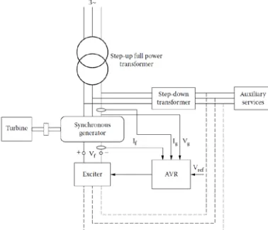
Synchronous generators are used almost exclusively in power systems as a source of electrical energy. The generator is supplied with real power from a prime mover, usually a turbine, whilst the excitation current is provided by the excitation system shown schematically in Fig .1. The excitation voltage E1 is supplied from the exciter and is controlled by the automatic voltage regulator (AVR). Its aim is to keep the terminal voltage V equal to the reference value Vref.
Although the AVR is very effective during normal steady-state operation, following a disturbance, the generator is in the transient state and the AVR may have negative influence on the damping of power swings. As power swings cause the terminal voltage to oscillate, the reaction of the AVR is to force field current changes in the generator which, under certain conditions, may oppose the
rotor damping currents induced by the rotor speed deviation ∆ω. This so-called negative damping may be eliminated by introducing a supplementary control loop, known as the power system stabilizer (PSS), also shown in Fig. 1. The task of the PSS is to add an additional signal VPSS into the control loop, which compensates for the voltage oscillations and provides a damping component that is
in phase with ∆ω[6].
Figure.1. Functional diagram of excitation control
mechanical energy into electrical energy. As the generation cost is considerable due to high price of diesel, therefore, such power stations are only used to produce small power [7].
II. METHODOLOGY
The proposed excitation system consists of synchronous generator, transformer, rectifier, exciter and AVR.
A. Exciter
[image:2.612.216.405.221.383.2]Exciter is the source of electrical power for the field winding of generator and is realized as a separate DC or AC generator. Exciter has its field winding in the stator, and armature winding in the rotor. In case of AC generator, as the rotor rotates, stator DC current induces a three-phase alternating current into the rotor winding. This AC current is rectified using diode, thyristor or transistor bridge installed in the rotor. Exciter is controlled by the AVR, which is very effective during steady-state operation, but, in case of sudden disturbances it may have negative influence on the damping of power swings, because then it forces field current changes in the generator.
Figure 2. Exciter with automatic voltage regulator
AVR acts upon the DC voltage Vf that supplies the excitation winding of SGs. The variation of field current in the SG increases or decreases the emf (no load voltage); thus, finally, for a given load, the generator voltage is controlled as required. The excitation system of an SG contains the exciter and the AVR. The exciter is, in fact, the power supply that delivers controlled power to SG excitation (field) winding. As such, the exciters may be classified into the following:
• DC exciters • AC exciters
• Static exciters (power electronics)
The DC and AC exciters contain an electric generator placed on the main (turbine-generator) shaft and have low power electronics control of their excitation current. The static exciters take energy from a separate AC source or from a step-down transformer and convert it into DC-controlled power transmitted to the field winding of the SG through slip-rings and brushes. The AVR collects information on generator current and voltage (Vg, Ig) and on field current, and, based on the voltage error, controls the Vf (the voltage of the field winding) through the control voltage Vcon, which acts on the controlled variable in the exciter.
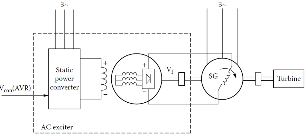
AC exciters basically make use of inside-out synchronous generators with diode rectifiers on their rotors. As both the AC exciter and the SG use the same shaft, the full excitation power diode rectifier is connected directly to the field winding of SG. The stator-based field winding of the AC exciter is controlled from the AVR. The static power converter now has a rating about 1/20(30) of the SG excitation winding power rating, as only one step of power amplification is performed through the AC exciter.
The AC exciter in Fig. 3 is characterized by the following: • Absence of electric brushes in the exciter and in the SG • Addition of a single machine on the main SG-turbine shaft
• Moderate time response in Vf (SG field-winding voltage), as only one (transient) time constant (Td0′) delays the response; the static power converter delay is small in comparison
• Addition of one torsional shaft frequency due to the flexibility of the AC exciter machine shaft and mechanical coupling
• Small controlled power in the static power converter: (1/20[30] of the field-winding power rating)
Figure 3. Alternating Current (AC) Exciter
In large alternators, the excitation system is provided by a small synchronous machine connected on the same shaft as the main synchronous generator. Current rectification is performed by a rotating diode bridge mounted on the synchronous machine shaft, thus avoiding slip rings for providing DC power to the synchronous generator field. Mechanical coupling of the synchronous generator and the exciter is done by using speed as mechanical input for the exciter machine [8].
The exciter is a small synchronous machine rated 8.1 kVA, 400V, 50Hz, 1500 rpm.
B. Automatic Voltage Regulator
Considering Figure 4, any change in the output voltage of the generator will change the terminal voltage. The voltage value measured by a voltage sensor is transmitted to AVR. Then AVR alters the terminal voltage of excitation system to keep the terminal voltage of generator at the desired value. The field current of generator changes by this way. This condition also changes the generated EMF. The power generation of the generator is adjusted to a new equilibrium point and the terminal voltage is maintained at the desired value. Block diagram of AVR system whose schematic diagram is presented in Fig. 4 is given in Fig. 5 [9].
[image:3.612.164.452.479.654.2]Figure 5. Block Diagram of AVR system
C. Transformer
A transformer is a device that uses the action of a magnetic field to change alternating current (AC) electric energy at one voltage level to AC electric energy at another voltage level. It consists of a ferromagnetic core with two or more coils wrapped around it. The common magnetic flux within the core is the only connection between the coils. The source of AC electric power is connected to one of the transformer windings. The second winding supplies power to loads. The winding connected to the power source is called primary winding, or input winding. The winding connected to the loads is called the secondary winding, or output winding [2]. In this paper, the step-down transformer rating is 10 kVA, 400V/12V.
D. Rectifier
Rectification is the process of converting alternating current or voltage into direct current or voltage. The DC output voltage is fixed in magnitude by the amplitude of the AC supply voltage. However, the DC output is not pure- it contains significant AC components called ripple. To eliminate this ripple, a filter is inserted after the rectifier. The main components of a semiconductor rectifier are semiconductor devices like the diode, thyristor, etc. the switching properties of these devices are used in rectifiers. Based on switching elements, these rectifiers are divided into two types [3]:
• Uncontrolled Rectifiers • Controlled Rectifiers
In this paper, rectifier output is about 12V.
III. SIMULATION AND RESULTS
Simulation of the paper represents the implementation of synchronous generator voltage generating with mechanical coupling of an excitation system. The simulation diagram is demonstrated by MATLAB/SIMULINK. Simulink model of voltage generating system is shown in Fig .6.
[image:4.612.42.550.500.702.2]In this Fig.6, the synchronous generator is 2MVA, 400V, 50Hz, 1500 rpm and machine driven by diesel engine. The step-down transformer rating is 8.1 kVA, 400V/12V. The generator output results are shown in Fig .7.
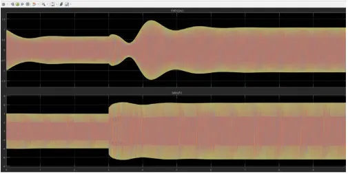
Figure 7. Simulation results of generator voltage and current
The simulation results of the generator voltage and current are shown in Fig 7. In this result, generating voltage is about 1 pu and current is initially 1000 A and after 3s the current is about 3000A.
Figure 8. Simulation results of exciter voltage and current
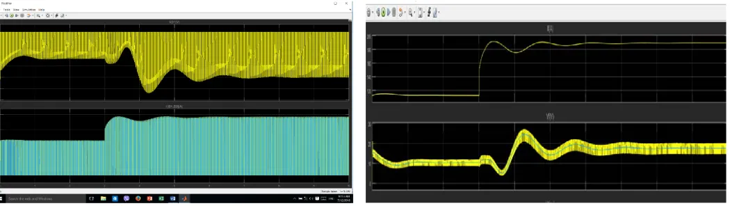
[image:5.612.37.542.429.682.2]Figure 9. Simulation results of diode voltage and current Figure 10. Simulation results of field voltage and current
The simulation results of the diode output voltage and current are shown in Fig 9. In this result, diode voltage is initially about -12V, after 3s the voltage is -20V and current is initially 120 A and after 3s the current is about 190A.
The simulation results of the field output voltage and current are shown in Fig 10. In this result, field voltage is initially about 10V, after 3s after the voltage is about 15 and current is initially 110 A and after 3s the current is about 190A.
IV. CONCLUSION
In this paper, the model of voltage generating system is about 400V. Voltage regulation of the generator is performed by controlling the field voltage of the exciter. To increase the efficiency and the performance of generating system, needs the control of turbine and excitation. The terminal voltage of the synchronous generator is kept as a constant to a predefined magnitude. Excitation control in synchronous generator is an important part to enhance the stability of power system.
ACKNOWLEDGEMENT
The author would like to thank of her teachers in Electrical Power Department of Mandalay Technological University, Yangon Technological University, Technological University (Kyaukse) for their supporting, encouragement, useful suggestions, invaluable guidance and help till the completion of this paper and also thanks to all the staffs of Electrical Power Engineering Department for their help and care.
REFERENCES
(1) PRABHA KUNDUR, Power System Stability and Control, Department of Electrical and Computer Engineering University of Toronto, Toronto, Ontario, 1994
(2) Philip Kiameh, Power Generation Handbook, Selection, Applications, Operation, and Maintenance The Mc.Grow.Hill Companies, 2003
(3) Alok Jain, Power Electronic and Its Applications, 2002
(4) P.C.SEN, Principles of Electric Machines and Power Electronics, Second Edition, University Kingston, Ontario, Canada, 1996.
(5) MD Singh, KB Khanchandani, Power Electronics, Second Edition, Laxmi Narayan College of Technology Bhopal, Department of Electronics and Telecommunication Engineering, SSGM College of Engineering Shegaon, Maharashtra, 2007.
(6) J.Machowski, J.W.Bialek, S. Robak, J.R.Bumby, Excitation control system for use with synchronous generators, Warsaw University of Technology, International Paper, October 1998.
(7) V.K.MEHTA ROHIT MEHTA, Principle of POWER SYSTEM, www.Engineering Books Pdf.com. (8) Control of Synchronous Generators in Power Systems, https:www.taylorfrancis.com
(9) Mahmut Temel Özdemir*1 , Vedat Çelik2, Stability analysis of the automatic voltage regulation system with PI controller, 1.Firat University, Faculty of Engineering, Department of Electrical and Electronics Engineering, 23119, Elazig, Turkey (e-mail:[email protected])
2 Firat University, Faculty of Engineering, Department of Electrical and Electronics Engineering, 23119, Elazig, Turkey (e- mail:[email protected]), Sakarya Üniversities Fen Bilimleri Enstitüsü Dergisi, vol. 21, no. 4: pp. 698-705, 2017