Journal of Chemical and Pharmaceutical Research, 2014, 6(8):118-124
Research Article
CODEN(USA) : JCPRC5
ISSN : 0975-7384
Effects of current density on capacitive deionization process using activated
carbon as an electrode
Ginno Lizano Andres
1*, Seiji Tanahashi
2, Masakazu Tanahashi
2*and Yoshinobu Yoshihara
11
Graduate School of Science and Technology, Department of Mechanical Engineering, Ritsumeikan University, Kusatsu, Shiga, Japan
2Tanah Process, Ltd., Osaka, Japan
_____________________________________________________________________________________________
ABSTRACT
We have discussed in our previous paper about an easy and low-cost ion reduction process of electrolytic solutions. In relation to this, we examined an ion removal technique using an active carbon with large surface area and create an electric double layer. Here, the adsorption rate change was dependent of on the process conditions. We proposed that this phenomenon exists in the pores of the active carbon’s surface. This is brought about by resistance which enables ion to be adsorbed in that area. We studied this phenomenon through an activated carbon electric double layer capacitor. As a result, we have discovered that the ion removal speed increases with increasing electrical conductivity of the ionic solution. When the ion concentration of the electrolytic solution is low, the ion removal rate decreases under constant adsorption speed. Here, we considered theoretical perspectives such as stopping the electric current temporarily and leaving it as is in order. This is done to let the electrode regain its current reception characteristics. We also decreased the current density for the electric charge rate to increase. Moreover, using these results as basis, we efficiently utilized the constant current anodizing process and we were able to lower the electrical conductivity to almost similar level of purified water.
Keywords: activated carbon, batch processing, electric double layer
_____________________________________________________________________________________________
INTRODUCTION
There are different kinds of existing processes of ion removal for aqueous solutions. These include distillation, ion exchange method, and reverse osmosis. Our objective is to study the capacity of an electrode for ion removal from aqueous solutions. Thus, we examined the ion adsorption process through an electric double layer generator using activated carbon.
In our previous paper, we examined a method that improved the ion adsorption efficiency [1], [2]. We created a multiple cell with an electrode made from activated carbon cloths arranged in parallel planar form. Aqueous ionic solution was poured and displaced in between the electrodes and direct current voltage was applied. This is referred to as batch condition. As a result, we discovered that the impurities can be efficiently removed at faster rate and high voltage in this condition. However, depending on the process conditions, the process efficiency also changes. For example, at constant DC current and longer exposure to the electrodes, the voltage rises and gas is evolved. In this paper, we present our observations and will explain how this phenomenon is related to the internal resistance of activated carbon cloth. We will also discuss large number of water decomposition reactions generated in different kinds of situations when applying electric current and voltage.
1.1 Theory
Using this principle, experiments were done on treating liquids by passing through from an inlet to an outlet [3]. In our previous paper, we reported that by using batch processing and by applying high voltage, it is possible to remove ion faster and more effectively than flow through capacitors [1], [2]. We observed a phenomenon that, for example, if the direct current flows in a constant current, the voltage rises and gas starts to be emitted, but if we leave it as is for a while, it regains its current reception characteristics. We think that this phenomenon is brought about by internal resistance distribution in electrodes.
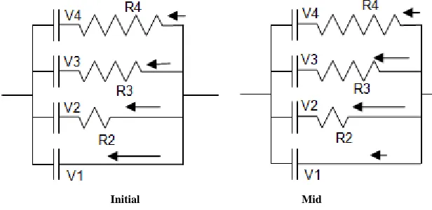
The capacity of the active carbon under batch condition, considering from the apparent surface to the internal area of the pores, is well distributed as shown in Fig. 1. There is an existing capacity from the apparent surface to the large area of resistance within the pores. That time, we have not measured the resistance distribution of the electrode. When we charged it with a fast current, initially it will be charged from the area close to the surface and with low resistance as shown in Fig 2. On the other hand, when it is already charged, for example in the case of positive electrode, the electric potential of the charged area will increase. Then, the electrode with the higher resistance starts charging on the area that has lesser charge. With this, the area that will have the capacity to receive the charge will shift to the area with higher resistance. In the case of constant current, even if the electric potential difference is set larger, current will still try to flow. The charge speed, which is also the speed in which ions are removed, is fast. But, for example in the anode, if it happens that the surface is charged, the electric potential rises but the ions cannot be removed. Ions will still be tried to be taken out from the pores on the deeper areas. The deeper areas have higher solution resistance so electric potential can rise higher. Here, if the potential is exceeds the value favorable for oxygen evolution, oxygen emission increases and the rate of adsorption, due to high resistance to current, will decrease.
Also, the charging process of electrode varies depending on the resistance. In the area close to the surface is the area with low resistance and the area with deep pores is the area with high resistance. The amount that is charged in these areas differs. The charging voltage is higher in the surface area with lower resistance, and lower in the deeper areas where resistance is much higher.
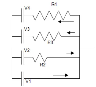
Here, when current is temporarily stopped and adsorption is halted, at that point, the voltage of the capacitor in the area with low resistance rises, and the voltage of the condenser in the area with high resistance decreases, and since both are within the same electrode, they are conductively connected. Thus, it will self-charge and discharge within the single pole as shown in Figure 3, and the condenser in the area close to the surface and with low resistance will discharge and the deep areas with high resistance will be charged, and ultimately, the ion adsorption area will be homogenized. When that happens, current reception is restored then it becomes possible again to charge with a high amount of current and remove ions.
In using charged activated carbon electrodes for ion removal method and to be able to remove ions fast, this phenomenon must be understood perfectly beforehand.
EXPERIMENTAL SECTION
2.1 Reagents and instrumentation
2.1.1 Samples and devices used in the experiment
We used an activated carbon cloth as the ion adsorption electrode. The activated carbon cloth was manufactured by Nippon Kynol Inc., Japan (Active Carbon Cloth, product number ACC5092-25, weight per area 100 ─ 130g/m2, thickness 0.5mm). The reaction area of the activated carbon cloth used in the experiment is 3cm x 5cm. For current collector, we used a titanium (Ti) foil plated with platinum (Pt). Also, for better electric collection, the 0.5mm φ Ti wire is plated with Pt, heated in 400°C and wired around the active carbon cloth as shown in Fig. 4.
For the power source, we used the DC voltage power supply MODEL 5244A manufactured by Metronix Corporation, Japan. Also, we used the conductivity meter DS-12 manufactured by Horiba, Ltd., Japan for electric conductivity measurements. For containers, we used 60ml and 45ml acrylic containers.
2.2 Ion Removal on Constant Current 2.2.1 Effects on Current Density
We prepared three pieces of 3cm x 5cm of activated carbon cloth electrode with the electric collector attached on the tip of the cloth (Fig. 4A), and both sides of the 45ml containers are arranged in parallel to the center. The space between the anode (A) and cathode (C) is about 6mm (A/C/A).
3 is kept constant, while the current varies between 20, 100, and 200mA.
Next, the same container is filled with an ion concentrated solution that is 3 times the amount of water, creating a NaCl aqueous solution. Here, we used the electrode which was wired around with an electric collector (Fig. 4B).
With regards to the concentration change within the scope of this experiment, the molar electric conductivity does not change much, so conductivity is proportional to the number of moles. This way, we used the change in conductivity as criteria for measuring ion removal amount.
2.2.2. Halting the Experiment from Large Current
We used the similar devices as described in 2.2.1 for this experiment, 6 pieces of wired electrode, 3 sets of anodes and cathodes particularly, anode/cathode-cathode (2 pieces piled)/anode-anode (2 pieces)/cathode, which are arranged as specified within the 45ml container. Here, the space between the electrodes is about 4mm. In this space, a 200mA direct current is applied, and then we conducted the experiment. The conductivity of the NaCl solution we used was 800µS/cm.
In experiment no. 9, we let the current flow continuously and measured the voltage change at that time. In experiment no. 10, we monitored the current, and at the point where the increase in voltage slows down, we halted the application of voltage, measured the transmission rate, and then re-applied the current on experiment no. 11, and continued applying voltage until its electric conductivity becomes the same as with experiment no. 9.
2.3 Preliminary Investigation on the Thorough Removal of Ions
We used 6 pieces of wired electrodes, and prepared 2 sets of the ff. arrangements: 3 sets of anodes and cathodes particularly, anode/cathode-cathode (2 pieces piled)/anode-anode (2 pieces)/cathode, which are arranged as specified within 45ml containers. Here, the space between the electrodes is 4mm.
On the 1st set, we performed the initial ion removal labeled as experiment nos. 13, 14, 15. Then we transferred the solution to the 2nd set where the active carbon electrode that does not adsorb ion is used. After which, we proceeded with the final ion removal experiment.
RESULTS AND DISCUSSION
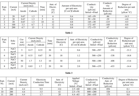
The results on the effects of current density to ion removal capacity of the electrodes are shown on Table 1 and Table 2. When comparing the results of using those with same current density (experiments 1, 2) on Table 1, we observed that the concentration phenomenon in 86µS/cm in 6C on the first half matches the decrease of ions, but on the latter half, only a portion of the concentration phenomenon in 29µS/cm is being adsorbed (2’). Here, the areas with low resistance are charged with the first half’s charge, and is also charged with the areas with high resistance in pores, so in the surface, a huge reaction potential enters, and the reaction current reached more amount than the charging current.
Looking at the current density on Table 1 (Experiments 2, 3, 4), the electric charge is the same, although just a little, the bigger the current density gets, the amount of ions removed lessens. This phenomenon is as mentioned in section 1, when the current gets high, when the current tries to enter the areas with the same resistance as from the surface, the IR drop gets bigger, and the reaction potential of the surface greatly exceeds, so electrolysis occurs, making the adsorption rate decrease.
However, this decrease of efficiency against the increase of current, when compared with the decrease mentioned beforehand, the decrease rate is less. Here, in the case of a large current, polarization increases as well as reaction, but the difference in electric potential internally is bigger and ion removal rate is also faster, so since processing can be done in a short period of time, the integral current of the reaction does not get that big. In other words, we discovered that initially, reception is possible even when using 13mA/cm2 of current density on active carbon cloth.
From the results shown on Table 2, in experiment no. 5, the current density in cathode is lowered to 0.33mA/cm2, and when amount of electricity is set to a low amount of 0.6C/cm2, it shows the best ion removal rate. In experiment no. 6 wherein the current density and amount of charging electricity are each set twice of the previous, the ion removal rate decreased but on the other hand, the removal speed and the amount removed increased, which are merits in exchange for a bit of decrease in efficiency.
However, in these cases, there are merits that the speed and the amount adsorbed both increased, which can be considered when necessary in choosing the appropriate amount of current.
Fig. 1 Equivalent circuit diagram of activated carbon electrode Vn = En─E0
E0: uncharged electric potential
En: charge potential of the capacitor connected to resistance Rn
Initial Mid
Fig. 2 Charging of activated carbon electrode (unipolar) Voltage when charging is halted: V1>V2>V3>V4
The results of the halting the experiment from large current are shown on Table 3. The shift of voltage during the experiment where 200mA was continuously applied is shown on Fig. 5. From the initial 2.5V voltage, as the ion decreases, the voltage gradually increases, and since it is running on a constant current, when the amount of ions decreases, the conductivity lowers and the increase of voltage speeds up. However, in this experiment, the increase of voltage slows down when it reaches around 40V, and at about the maximum of 70V, the voltage decreases a little. Here, it can be observed that the electrolysis of the water simultaneously occurs at about approximately 40V, and at this point, the speed of ion removal decreases. Moreover, it can also be observed that the temperature of the solution also increases, so conductivity decreases, and voltage also decreases a little.
Thus, in the next experiment, at that point when the voltage increase weakens, in other words, at that point when the water electrolysis starts to occur, the application of current is halted (around the arrow on Fig. 2). Here, the conductivity is 280µS/cm, and at this point, approximately 65% of chlorine ion and sodium ion was removed. Ten minutes after, voltage application was halted and necessary measurements were performed, we re-applied 200mA current and the applied voltage lowered to 4.4V. With regards to this aspect, we thought that there are two reasons why current reception became better, one, during the measurement of the electric conductivity of the area where a spacer is inserted into electrodes and ions have difficulty in moving, it has been homogenized and the conductivity of the aqueous solution has been restored a little; and two, the areas which are close to the surface and have low resistance, as shown on Fig. 3, performs self-charging and discharging so the amount of charge decreases.
[image:4.595.167.447.115.256.2] [image:4.595.152.460.321.471.2]Fig. 3 Self-charging and discharging within the activated carbon electrode (unipolar) When self-charging and discharging is completed, V1=V2=V3=V4
Fig. 4 Activated carbon cloth electrode, Effective area = 30mm×50mm
Comparing this from the previous experiment, the amount of ions removed is the same but the amount of electricity used is just about enough. In other words, in the latter part of the previous experiment, most of the electricity was used only on the reaction. Moreover, from another point of view, by letting current flow on a condition that reaction will not occur, we confirmed that if there is enough amount of active carbon, ions can be removed swiftly with the application of high voltage.
We think that this is a significant method that can be used in the softening of hard water.
Pt plated
Ti Wire Pt plated
Ti Foil
[image:5.595.161.474.82.365.2]Fig. 5
[image:6.595.65.552.335.672.2]Table 1
Table 2
Expt. No. Solu-
tion Cur- rent [mA]
Current Density [mA/cm2] Time
[min]
Amount of Electricity
[C]
Amt. of Electricity per unit area [C/cm2]Cathode
Conductivity [µS/cm] Initial→Final
Conductivity Amt. of Reduction
[µS/cm]
Degree of Reduction per
unit area [µScm-1/C]
Anode Cathode
5 NaCl
aq.sol 5 0.17 0.33 30 9 0.6 588→397 -191 -21.2
6 NaCl
aq.sol 10 0.33 0.67 30 18 1.2 588→250 -338 -18.8
7 NaCl
aq.sol 50 1.7 3.3 10 30 2.0 588→180 -408 -13.6
8 NaCl
aq.sol 25 0.83 1.7 20 30 2.0 588→155 -433 -14.4
Table 3 Expt. No. Current [mA] Current Density [mA/cm2]
Electricity Conduction Time [min] Amt. of Electricity [C] Applied Voltage [V] Initial→Final
Conductivity [µS/cm] Initial→Final
Conductivity Amt. of Reduction
[µS/cm]
Degree of Reduction per unit area
[µScm-1/C]
9 200 4.4 9.5 114 2.5→60 800→106 694 6.1 10 200 4.4 3.5 42 2.5→70 800→280 520 12.4 11 200 4.4 1.7 20 4.4→83 280→105 175 8.8
The results of the investigation of preliminary removal of ions experiment are shown on Table 4. In order to understand this experiment, taking the previous experiment no. 10 which had high concentration and comparing it to this experiment no. 12, regardless of whether the current density is the same or the amount of electricity applied is a little different, just by reducing the amount of electricity, the results were greatly affected.
This means that, even if there is enough capacity in the active carbon’s pores, it shows that the polarization of
Expt. No. Current [mA] Current Density [mA/cm2] Time [min] Amt. of Electri- city [C]
Amount of Electricity per unit area [C/cm2]Cathode
Conducti- vity [µS/cm] Initial→Final
Conducti- vity Amount of
Reduction [µS/cm]
Degree of Reduction per unit
area [µScm-1/C]
Anode Cathode
1 20 0.67 1.3 5 6 0.4 145→59 -86 -14.3 2’ 20 0.67 1.3 5 6 0.4 59 →30 -29 -4.8
electrodes does not depend only on current density. Considering this on the equivalent circuit in Fig. 1, active carbon only has pores, and its resistance is proportional to the ion conductivity of the solution that exists in the pores. That is why, in order to achieve the same efficiency, in other words, the same extent of polarization and decomposition reaction of water, electric conductivity should be in proportion and current must be flowing.
Furthermore, here, while ions are being taken, we lowered the current density as appropriate, but ultimately, since the rate of the decrease of current is not proportion to the concentration, the rate of the decrease in ion concentration gradually worsened. This is the effect of the increase in resistance to polarization brought about by ion reduction, overlapped with the charging of areas close to the surface by areas with low resistance, thus the great decrease in reduction rate.
Comparing experiment nos. 14 and 15, the current density of experiment no. 15 is lowered a little, and conductivity is lower by 1 order, but regardless of that, the reduction rate was still at the same level. The reason is that, we continuously experimented on experiment no. 15, and since charge distribution has not been homogenized, those within the pores get to be used for ion removal, which shows that polarization becomes greater, which suggested that the discharge (ion desorption) must be done thoroughly.
Table 4
Expt. No.
Current [mA]
Current Density [mA/cm2]
Electricity Conduction Time
[min]
Amt. of Electricity
[C]
Applied Voltage [V] Initial→Final
Conductivity [µS/cm] Initial→Final
Conductivity Amt. of Reduction
[µS/cm]
Degree of Reduction per unit area
[µScm-1/C]
12 200 4.4 3 36 10→120 170→61 109 3.0
13 50 1.1 5 15 10→50 →30 31 2.1
14 30 0.67 15 27 10→40 →15 15 0.55
15 20 0.44 20 24 →2.1 13 0.54
CONCLUSION
We investigated a method of ion removal from an aqueous solution, using electric double layer and active carbon in batch method, studied the difference in efficiency in case the method was done in constant current, and as a result, we discovered the following points:
1) In the active carbon electrode, there exists a capacity from the areas of the solution near the surface and with low resistance to the deep pore areas of the solution with high resistance. That is why, in the case when the capacity is not much used in the initial charging, even if there is high current density, there is not much polarization, and decomposition of the water does not occur, and in the latter part, polarization increases and ion removal rate decreases.
2) Even if a high current density is present, the initial ion removal rate does not drop.
3) When charging is temporarily halted at the appropriate time, the charge within the electrode becomes homogenized through self-charging and discharging, so its current reception regains.
4) When electrolysis of the water occurs greatly, the current mostly gets used only on that reaction, so ion removal rate decreases. When the reaction starts, by temporarily halting the current, the current density drops and ion removal can be done fast and effectively.
5) By properly adjusting the current, we were able to decrease the ion concentration to the same level as purified water.
We plan to measure the internal resistance in the active carbon electrode and capacity distribution in the future.
REFERENCES
[1] Tanahashi, M. and Tajima, I. 1985a. “Study on Electric Double Layer Capacitor 1 – Equivalent Circuit of Double Layer Capacitor” CPM85-98 (1985)
[2] Tanahashi, M. and Tajima, I. 1985b. “Study on Electric Double Layer Capacitor 3 – Discharge Characteristics of Electric Double Layer Capacitor” CPM85-98 (1985)