Mathematical Modeling of Transient Processes of the
Automatic Control System of Water Level in the
Steam Generator
Siddikov Isamiddin Xakimovich, Umurzakova Dilnoza Maxamadjonovna*
Department of Information Processing Systems and Management, Tashkent State Technical University, Uzbekistan
Copyright©2019 by authors, all rights reserved. Authors agree that this article remains permanently open access under the terms of the Creative Commons Attribution License 4.0 International License
Abstract
The methodology of creation of automatic control system (ACS) of water level in the steam generator is developed. The mathematical model of checking its working capacity is developed, which allows establishing the maximum deviations of water level without carrying out full-scale tests, without adjusting the settings of tripping actuation according to the water level in the drum. The foreign methods of PID-regulator adjustment in the cascade system of automatic water level control in the boiler drum are considered, on the basis of which an invariant cascade system of automatic control is proposed. The invariant Cascade-System of Automatic Control (CSAC) of water level in a boiler drum is offered. Simulation results of the invariant cascade-system of automatic control in comparison with CSAC, configured with best foreign method, showed a significant improvement in the quality of regulation in all the major disturbing influences. The results can be used in the development of adaptive control systems and other thermal power devices.Keywords
Automatic Control Systems, Cascade Automatic Control System, PID-regulator, Steam Generator, Water Level, Transfer Function1. Introduction
Automation of power equipment of power plants is carried out in many directions, with one of the main being the regulation of the water level in the boiler drum (steam generator). The quality of regulation of the water level in the drum boilers of thermal power plants (TPP) and of steam generators of nuclear power plants (NPP) largely determine the reliability and efficiency of thermal power plants and nuclear power plants. In accordance with this, the issues of significant improvement in the quality of water level regulation in the boiler drum (steam generator)
become urgent.
Three-pulse automatic control systems (ACS) of the water level in the drum are most widespread at TPP and NPP [1-3]. The use of classical regulators with a rigid feedback device in these ACS increases the stability of the system, but does not provide quality control of the water level in the boiler drum [4, 5]. A typical three-pulse ACS of the water level in the boiler drum has such disadvantages as:
necessity of availability of three measurement sensors (level, superheated steam flow and feed water)
the presence of a static control error at the end of the transition process at the internal perturbation, as well as at the external perturbation of the flow rate of superheated steam with the phenomenon of “level swelling” [3].
For elimination of the specified shortcomings in [5] on the example of ACS of the boiler BKZ-210-140 it is offered to use structural-parametric optimization of cascade ACS. In this case, the elimination of the static control error in the development of internal perturbation is carried out by the stabilizing regulator, and elimination of a static error of regulation at working off of extreme external disturbance with the phenomenon of “level swelling” is made by the corresponding choice of structure of the correcting device, as well as with the correction of tasks to the last value of the static regulation error at the point of time when the main control value stabilizes. However, in this case, the integral of the control error module in terms of the level when testing external disturbances, although less than in a typical three-pulse ACS, however, there is a possibility of significant improvement in the quality of water level regulation.
2. Materials and Methods
provide the best control quality for thermal power facilities. Cascade automatic control system is widely used in the field of automation of technological processes [6, 7]. The water level in the drum of the steam generator when perturbed by the flow of feed water refers to objects without self-leveling and is described by the transfer functions of the ideal integrating link with delay
( )
p
T
e
p
W
p1 1
1
τ −
=
, (1)where
T
1 – the time constant of the integrating link;τ
1– time of delay on the channel of regulating influence;p
– Laplace operator.In addition, the experimental curve on the water level in the boiler drum under the disturbance of feed water flow can be represented as a real integrating link of the type
( )
(
)
1
1
1 1 *
1
p
=
T
p
p
+
W
τ
. (2)The dynamics of the controlled object in terms of the perturbation of the flow rate of feed water and superheated steam of the steam generator BKZ-210-140 has the following parameter:
τ
1=
21
s;T
1=
37
s [3]. Thetransfer function of the external perturbation of the flow rate of superheated steam with the phenomenon of “level swelling” of water in the boiler drum can be approximated by the difference between the transfer functions of the first-order inertial link and the ideal integrating link of the
form [8]
( )
( )
p
T
p
T
k
p
W
p
W
p
W
p4 3
3 3
2
*
1
1
)
(
−
+
=
−
=
, (3)where
T
3=
20
s;67
4=
T
s;k
3=
,1
5
.In this case, the value of the “level swelling” will be the greater the numerical value of the transfer coefficient of the inertial link of the first order
k
3. The transfer function of the flue perturbation has the form of an inertial link of the first order( )
1
30
5
1
=
+
+
=
p
p
T
k
p
W
p p
p , (4)
where
k
p – the gain of the perturbation;T
p– the time constant of the furnace perturbation. The transfer function of the leading section of the feed water flow rate during the abrupt movement of the control valve has the form of an inertial link of the second order( ) (
) (
) (
10
1
) (
,1
2
1
)
1
1
1
le lele
le
p
=
T
p
+
k
⋅
p
+
=
p
+
⋅
p
+
W
σ
.(5) where
k
le – transmission coefficient;T
le – large time constant of the leading section;σ
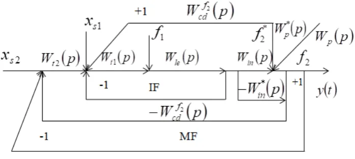
le – smaller time constant of the leading section. The block diagram of the boiler power supply CSAC modeling is shown in Fig. 1.Figure 1. Structural scheme of modeling of boiler power supply CSAC:
y
( )
t
–the main adjustable value (water level in the boiler drum);x
s1– the set value of the intermediate adjustable value;x
s2– the set value of the main controlled variable;f
1 – internal perturbation;f
2 – external flue perturbation;f
2* – external perturbation of the flow rate of superheated steam;W
t1( )
p
– the transfer function of the stabilizing regulator;( )
p
W
t2 – the transfer function of the corrective regulator;W
le( )
p
– the transfer function leading section of the object of regulation;W
in( )
p
[image:2.595.113.484.468.636.2]The method of determining the optimal parameters of the dynamic adjustment of the controllers of the standard CSAC is based on the possibility of calculating one circuit independently of the other. First, the stabilizing regulator is adjusted, and then the dynamic adjustment of the correcting regulator is calculated. Typically, the standard CSAC is used as a corrective and stabilizing regulator PI-regulators for the formation of regulatory impact, although it is known that of all linear regulators, PID-regulators provide the best quality of transients. In this regard, we will replace the PI-regulators of CSAC to PID-regulators. In this case, the output of the transfer function of the optimal stabilizing regulator is made on the basis of the inverse model of the controlled object and a given optimal transfer functions of closed ACS for the driving force. We write down the transfer function of the closed ACS
W
y,xs1( )
p
on the driving force( )
( ) ( )
( ) ( )
p
W
p
W
p
W
p
W
p
W
t t x y s le 1 le 1, 1
=
1
+
. (6)The transfer function of the internal circuit is selected so that it meets the quality criterion for the driving force:
( )
p
W
( )
p
W
opts x
y,s1
=
1 , (7)where
W
sopt1( )
p
- optimal transfer function of the internal circuit on the driving force.Given (7), the transfer function (6) will take the form
( )
( ) ( )
( ) ( )
p
W
p
W
p
W
p
W
p
W
t t opt s le 1 le 11
=
1
+
. (8)From (8) we find the optimal transfer function of the stabilizing regulator
( )
( )
( )
( )
p
W
p
W
p
W
p
W
opt s opt s t 1 1 le1
=
1
⋅
1
−
, (9)where
W
t1( )
p
– the optimal transfer function of the controller, which implements a given optimal transfer function of the internal circuit of the ACS for the driving forcex
s1.We make a choice of structure and optimum dynamic adjustment of the stabilizing regulator. Since the transfer function of the leading section (5) has a second order,
opt s
W
1 we take the following form:( )
(
)
2 1 11
1
+
=
p
T
p
W
s opts , (10)
where
T
s1– a given time constant of the inertial link of thesecond order.
Substituting (5) and (10) into (9), we obtain (for the stabilizing controller) the transfer function of the real PID-regulator with one parameter of dynamic adjustment
1 s
T
( ) (
) (
) (
) (
)
+
+
⋅
+
=
+
+
⋅
+
=
1
2
2
1
2
,1
1
10
1
2
2
1
1
s1 1 s1 1 le le le 1p
T
p
T
p
p
p
T
p
T
k
p
p
T
p
W
s s tσ
. (11) Determination of the numerical valueT
s1 is carried out using numbers of the Golden section rule [9], taking as an integer * le le11
,
2
le
=
T
+
σ
=
T
s. We select the followingvalue of the time constant of the criterion of optimal processing of the task by the inner contour:
63
,
1
146
,
0
* le 1=
T
=
T
s с. (12)Adjustment of the corrective regulator (Table 1) can be carried out using some foreign methods. As a rational structure of the controller, we choose the classical PID-regulator, the transfer function of which has the following form [10]:
( )
N
T
p
pT
p
T
K
s
G
d d i c+
+
⋅
+
=
1
1
1
1
, (13)where
K
c –transmission coefficient of the regulator;T
i – time of integration of the regulator;T
d – time of differentiation of the regulator;N
– the coefficient of reduction of the time of differentiation in the formation of the ballast time constant of the regulator.3. Discussion
According to [10], the selected controller is used in the following products: Toshiba TOSDIC 200 product with
10 ≤ ≤ 33 ,
3 N 3.33 (McMillan, 1994); Foxboro EXACT Model 761 product with
N
=
10
(McMillan, 1994); Honeywell T DC 3000 Process Manager product – Type A ,interactive mode withN
=
10
(ISMC, 1999), according to which the numerical value of the coefficientN
let us take 10, because with a decrease in the ballast component of the transfer function, the real controller in dynamics approaches the ideal one.Table 1. Foreign methods for dynamic tuning of the PID-regulator [10] The author of the optimization methods
(year) Parameters for dynamic controller settings
Ford (1953)
=
1
,
48
=
2
,
6
1 1
τ
T
k
p ;T
i=
2
τ
1=
41
s
;T
d=
0
,
37
τ
1=
7
,
77
s
Hay (1998)
=
0
,
4
=
0
,
7
1 1
τ
T
k
p ;T
i=
3
,
2
τ
1=
67
,
2
s
;T
d=
0
,
8
τ
1=
16
,
8
s
NI Labview (2001)
=
1
,
1
=
1
,
93
1 1
τ
T
k
p ;T
i=
2
τ
1=
42
s
;T
d=
0
,
5
τ
1=
10
,
5
s
Sree and Chidambaram (2005)
=
0
,
896
=
1
,
57
1 1
τ
T
k
p ;T
i=
2
,
5
τ
1=
52
,
5
s
;T
d=
0
,
55
τ
1=
11
,
55
s
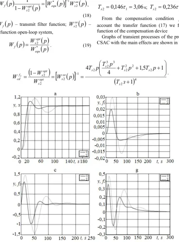
Figure 2. Graphs of transients CSAC power boiler: a – the practicing the jump master effects of
x
s; b – the practicing the jump internal disturbance1
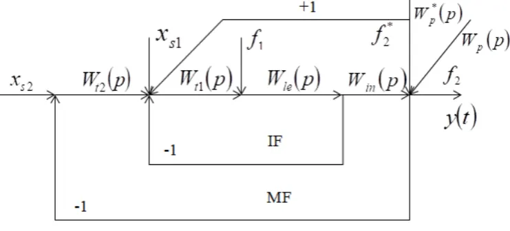
Figure 3. Block diagram of the simulation of the invariant CSAC of the steam generator:
W
cdf2( )
p
– the transfer function of the externaldisturbance compensation device;
W
in*( )
p
– the transfer function model of the inertial section of the object of regulation, adequateW
in( )
p
(other designations in Fig. 1)From the transient graphs it can be seen that when a jump of the task is developed, an overshoot appears up to 50%, the minimum adjustment time is 250 s. When working out the internal and external disturbances static regulation errors are absent, the minimum regulation time is 300 seconds. The minimum values of the maximum dynamic regulation error are as follows: when practicing an internal disturbance, from + 3.0 to –2.5%; when developing external similar disturbances - from +36.0 to – 25.0%; during the development of external excitation with steam consumption - from +58.0 to –22.0%. The best direct quality indicators for key impacts are consistent with the NI Labview method. (2001) (Table 1) (
k
p=
1
,
93
;42
i
=
T
с;T
d=
10
,
5
s).The disturbed influences affect the controlled value, the most dangerous being the disturbance of the flow of superheated steam applied to the ACS output. In the invariant ACS, the influence of the disturbance on the regulated value is compensated by introducing an additional signal to the regulator input from the output of the compensating device of the corresponding structure. The block diagram of the simulation of the proposed invariant CSAC of the steam generator power supply is shown in Fig. 3.
The choice of the rational structure and parameters of the optimal dynamic adjustment of the correction regulator is made on the basis of the transfer function of the optimal regulator. To do this, we determine the transfer function of the equivalent object, taking into account the transfer functions of the object (2) and the specified transfer function of the internal contour (10)
( )
( )
(
) (
)
2s1 1
1 s1 ob
1
1
1
+
⋅
+
=
=
p
T
p
p
T
W
p
W
p
W
optequ
τ
.(14) The dynamics of control objects with self-leveling are
described by the transfer functions of inertial links, and the dynamics of control objects without self-leveling, which include the water level in the boiler drum, by the transfer functions of integrating links. In this case, the graphs of transient processes for these objects with a jump in the regulating effect will coincide until the time when the controlled object with self-leveling does not begin to stabilize the graph at the steady-state value. Based on this property, up to a certain point there is no difference what transfer function describes the dynamics of the control object without self-leveling (transfer function of a real integrating link or transfer function of an inertial link of the second order). Stemming from this, the transfer function of an equivalent object can be represented in the form of a second-order inertial link, as for an object of regulation with self-leveling:
( ) (
1
) (
1
)
1
1 1
*
1
p
=
T
p
+
⋅
p
+
W
τ
. (15)In this case, the transfer function of the equivalent object (14) takes the following form:
(
) (
) (
)
21 1
1 *
1
1
1
1
+
⋅
+
⋅
+
=
p
T
p
p
T
W
s
equ
τ
. (16)Since the transfer function of the equivalent object (16) is of the fourth order, the specified transfer function
( )
p
W
opts2 criterion of optimality of the main regulated
value when developing a job jump
x
s2 takes the following form:( )
(
)
4 2 21
1
+
=
p
T
p
W
s opt
s , (17)
[image:5.595.127.476.83.239.2]Substituting (16) and (17) into (9), we obtain the transfer function of the correction device with one parameter of dynamic tuning
T
s2( )
( )
( )
[
W
( )
p
]
W
( )
p
p
W
p
W
p
W
oss equ
opt s f
t 2
1 *
2
2
1
1
−
=
−
=
,(18) Where
W
f( )
p
– transmit filter function;W
sos2( )
p
– the transfer function open-loop system,( )
( )
( )
p
W
p
W
p
W
equ opt s
f
=
*2 . (19)Selection of numerical values
T
s2– using the number of numbers, we carry out the gold section rules [9], taking the integerτ
1. Select the following values given by the time constant:06
,
3
146
,
0
12
=
τ
=
s
T
s;T
s2=
0
,
236
τ
1=
4
,
96
s. (20) From the compensation conditionf
2 taking into account the transfer function (17) we find the transfer function of the compensation deviceGraphs of transient processes of the proposed invariant CSAC with the main effects are shown in Fig. 4.
(
)
[
( )
]
(
)
4 22 2
2 2 3 3
2 2 1 2 2
2
1
1
5
,1
4
4
1
2
+
+
+
+
=
=
−
=
−з
T
p
T
p
T
p
T
p
T
p
W
W
W
W
s
s s
s s os
s opt
s opt s f
cd
. (21)
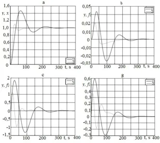
Figure 4. Graphs of transient processes of the invariant CSAC with the main effects: a – the practicing the jump master effects of
x
s; b – the practicing the jump internal disturbancef
1; c- the practicing the jump external flue disturbancef
2; g - the practicing the jump external disturbance flow of superheated steamf
2; t - time, s.(
)
,1
63
146
,
0
1
−
T
s1=
T
le+
σ
le=
s,T
s2=
0
,
146
τ
1=
3
,
06
s;(
)
,1
63
146
,
0
[image:6.595.104.473.137.634.2]From the transient graphs it can be seen that when a job jump is completed, the overshoot occurs to 18 %, the minimum adjustment time is 160 s. When working out internal and external disturbances, static regulation errors are absent, the minimum adjustment time is 240 s. The minimum values of the maximum dynamic regulation error are as follows: when practicing an internal disturbance, from +2.00 to –0.52 %; when working out external furnace disturbances from +22 to –18 %; when developing external disturbances with steam consumption from +35 to –18 %. The best direct quality indicators correspond to the numerical values:
T
s1=
0
,
146
(
T
le+
σ
le)
=
,1
63
s;06
,
3
146
,
0
12
=
τ
=
s
T
s.4. Result
A comparative analysis of the result of simulating a
CSAC with a PID-regulator configured by the best foreign method (curve 1) and the proposed invariant CSAC (curve 2) is presented in Fig. 5.
From the analysis of transient graphs it can be seen that the proposed invariant CSAC increases the response rate when developing a task jump 2.5 times. In this case, the maximum value of the overshoot decreases from 42.5 to 10.0 % compared with the best foreign analogue. When working out internal disturbances, the regulation time is reduced by 33 %, the maximum dynamic regulation error - by 65 %. The degree of attenuation of the transient process increases from 0.85 to 1.00. The time for working out the external furnace disturbance is halved; the maximum dynamic control error is reduced by 63 %; the maximum dynamic regulation error during the development of external disturbances by the flow of superheated steam by 71 %, the regulation time is reduced by 1.5 times.
[image:7.595.133.465.314.610.2]5. Conclusions
1. An invariant cascade system of automatic control of the water level in the boiler drum is proposed, which differs from the typical one in that:
the structure and optimal dynamic setting of the stabilizing regulator is selected on the basis of the transfer function of the optimal regulator, while the specified time constant of the optimality criterion is selected according to the golden section rule, taking the equivalent time constant of the leading section as an integral variable;
the structure and the optimal dynamic setting of the correction device are selected on the basis of the transfer function of the optimal controller taking into account the transfer function of the equivalent control object, including the internal loop of the stabilizing controller. In this case, the transfer function of the correction device corresponds to the product of the inverse transfer function of the equivalent control object by the specified transfer function of the open-loop system by the main regulated value;
the transfer function of the model of the inertial part of the control object at the time of the development of external disturbances by the flow of superheated steam is dynamically represented by the control object with self-leveling;
the structure of the transfer function of the external disturbance compensation device corresponds to the inverse given transfer function of the open-loop system and is chosen so that it is not necessary to additionally determine the dynamic parameters of the transfer function of the external disturbance.
2. The results of the simulation of an invariant cascade-system of automatic control in comparison with the CSAC tuned by the best foreign method showed a significant improvement in the quality of regulation with all the main disturbing influences.
REFERENCES
Aidan, O’Dwyer, Handbook of PI and PID Controller [1]
Tuning Rules. 3rd Edition. Dublin: Institute of Technology; Ireland, Imperial College Press, 2009. 529 p.
Astrom K. J. Advanced PID control/ K. J. Astrom, T. [2]
Hagglund – ISA (The instrumentation, Systems, and Automation Society), 2006 – 460 p.
C. Lu, C. Hsu, and C. Juang, Coordinated control of flexible [3]
AC transmission system devices using an evolutionary fuzzy lead-lag controller with advanced continuous ant colony
optimization, IEEE Transactions on Power Systems, vol. 28, no. 1, pp. 385–392, 2013.
D. Pelusi and R. Mascella, Optimal control algorithms for [4]
second order systems, Journal of Computer Science, vol. 9, no. 2, pp. 183–197, 2013.
D. Pelusi, PID and intelligent controllers for optimal timing [5]
performances of industrial actuators, International Journal of Simulation: Systems, Science and Technology, vol. 13, no. 2, pp. 65–71, 2012.
Demchenko, V.A., Automation and modeling of [6]
technological processes at nuclear power plants and thermal power plants / V. A. Demchenko. - Odessa: Astroprint, 2001. - 308 p.
Pletnev, G.P., Automation of Technological Processes and [7]
Productions in Heatand-Power Engineering. 4th Edition. Moscow: Publishing House Moscow Power Engineering Institute, 2007. -352 p.
Rotach, V.Ya., The Theory of Automatic Control. Moscow: [8]
Publishing House Moscow Power Engineering Institute, 2008. - 396 p.
Siddikov I.X., Iskandarov Z., Synthesis of adaptive-fuzzy [9]
control system of dynamic in conditions of uncertainty of information // International Journal of Advanced Research in Science, Engineering and Technology. Vol. 5. Issue 1. January 2018 y. pp. 5089-5093.
Sidikov I.X., Umurzakova D.M., Adaptive neuro-fuzzy [10]
regulating system of the temperature mode of the drum boiler // International Journal of Advanced Research in Science, Engineering and Technology. Vol. 6. Issue 1. January 2019 y. pp.7869-7872.
Soroko, E.M., Golden Sections, Processes of [11]
Self-Organizing and Evolution in Systems: Introduction into the General Theory of System Harmonizing. Moscow: KomKniga, 2006. -264 p.
T. Kim, I. Maruta, and T. Sugie, Robust PID controller [12]
![Table 1. Foreign methods for dynamic tuning of the PID-regulator [10]](https://thumb-us.123doks.com/thumbv2/123dok_us/8757419.893203/4.595.75.524.89.680/table-foreign-methods-dynamic-tuning-pid-regulator.webp)